Nondisruptive Data Center Network System Maintenance Best Practices with Cisco Nexus 9000 and 3000 Series Switches White Paper
Available Languages
Bias-Free Language
The documentation set for this product strives to use bias-free language. For the purposes of this documentation set, bias-free is defined as language that does not imply discrimination based on age, disability, gender, racial identity, ethnic identity, sexual orientation, socioeconomic status, and intersectionality. Exceptions may be present in the documentation due to language that is hardcoded in the user interfaces of the product software, language used based on RFP documentation, or language that is used by a referenced third-party product. Learn more about how Cisco is using Inclusive Language.
Nondisruptive data center network system maintenance overview
During the past decade, data center design has evolved in all its aspects. Advances made in compute technology, server virtualization technology and storage technology, etc., are driving the evolution of application architecture. The data center infrastructure is beholden to applications; as applications have evolved from giant monolithic application architecture to scaled-out, distributed architecture, the data center network design also evolved, from a traditional three-tier core-aggregation-access scale-up to a scale-out spine-and-leaf architecture, to better serve the application. This evolution is shown in Figure 1.
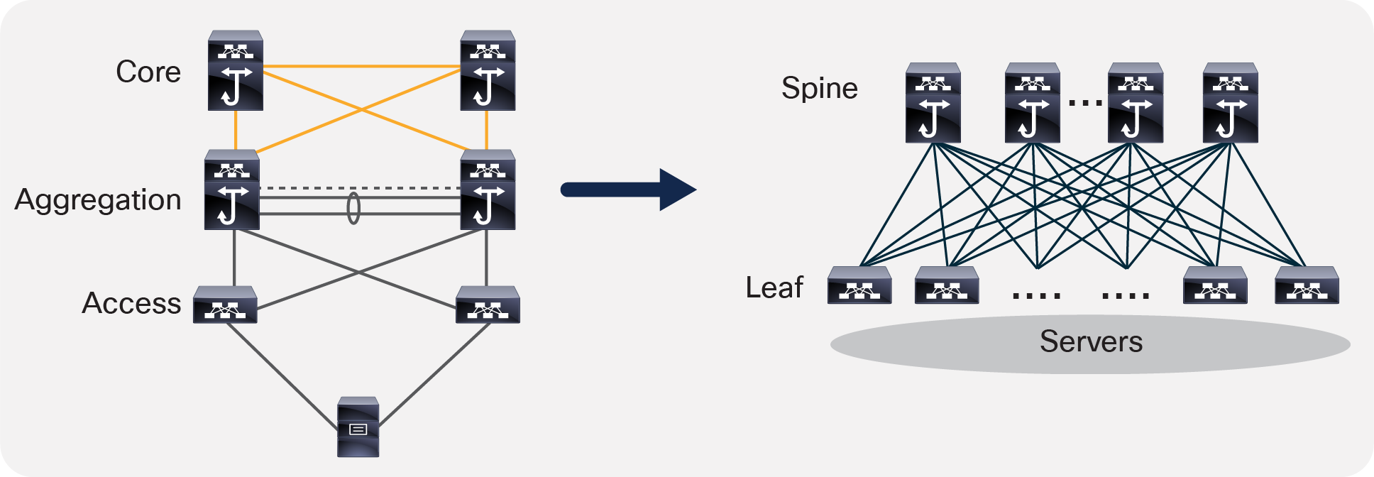
Traditional three-tier, scale-up design evolves to a spine-and-leaf, scale-out design
The scale-out, spine-and-leaf architecture provides much better redundancy and high availability. For example, with four or eight spines at the spine layer, if one of the spine switches fails, it loses 25 percent or 12.5 percent of the spine layer capacity. The rest of the spine switches can easily pick up the load. The failure impact is much less than the 50 percent capacity loss caused by a giant aggregation switch failure in the traditional three-tier, scale-up data center architecture.
With the spine-and-leaf architecture, the way that IT teams maintain the availability of the network has also evolved. To keep a single device up 24x7 becomes less important as long as the network stays up 24x7 to serve the application traffic seamlessly. Also, as a data center scales with tens of thousands of devices, maintenance work becomes more frequent; for example, at any moment, issues caused by malfunctioning switch hardware or port flapping due to bad optics or software bugs, etc., may pop up. The way that data center operation teams manage the maintenance work also evolved. In this context, the maintenance operations mean many different things, such as hardware replacements, software upgrades, EPLD upgrades, software bug patching, troubleshooting, configuration modifications, etc. To perform these maintenance operations effectively and consistently without impacting application performance, the operators preferred to isolate a networking device from the forwarding path, perform the necessary maintenance, and then bring the device back into the network. With this new capability, which puts a device into maintenance mode with removing the device from data forwarding path, IT teams have a consistent operational model for a variety of maintenance tasks, greatly simplifying data center management and operation.
Another evolution or trend that has emerged is the chassis type of switch that is used in various layers of the network design. With Top-Of-Rack (TOR) switch design being increasingly used, it has become common practice to use fixed switches either 1-RU or 2-RU in the leaf layer or access layer. For spine or aggregation or core layers in some designs, modular chassis models with line cards are very popular, even though high-density fixed switches have begun to appear at these layers in some designs. Figure 2 shows the platform choice for two-tiered spine-leaf design. Figure 3 shows the platform choice for a three-tiered spine-leaf design.
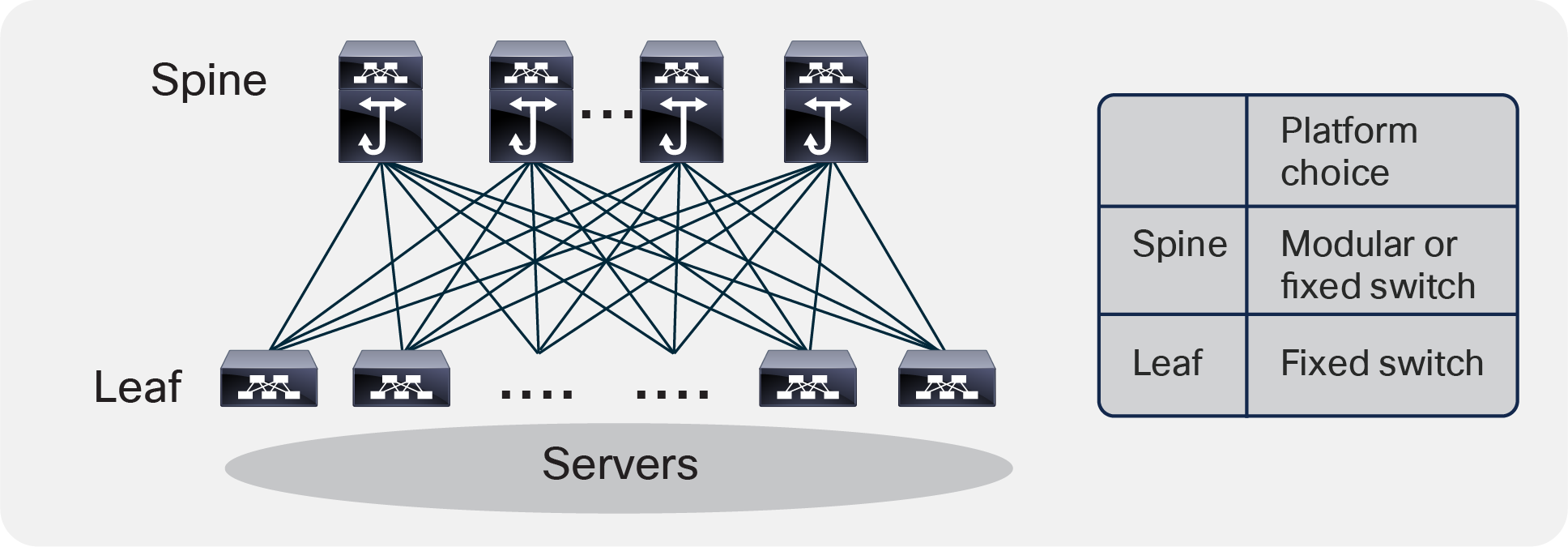
Two-tiered spine-leaf design platform choice
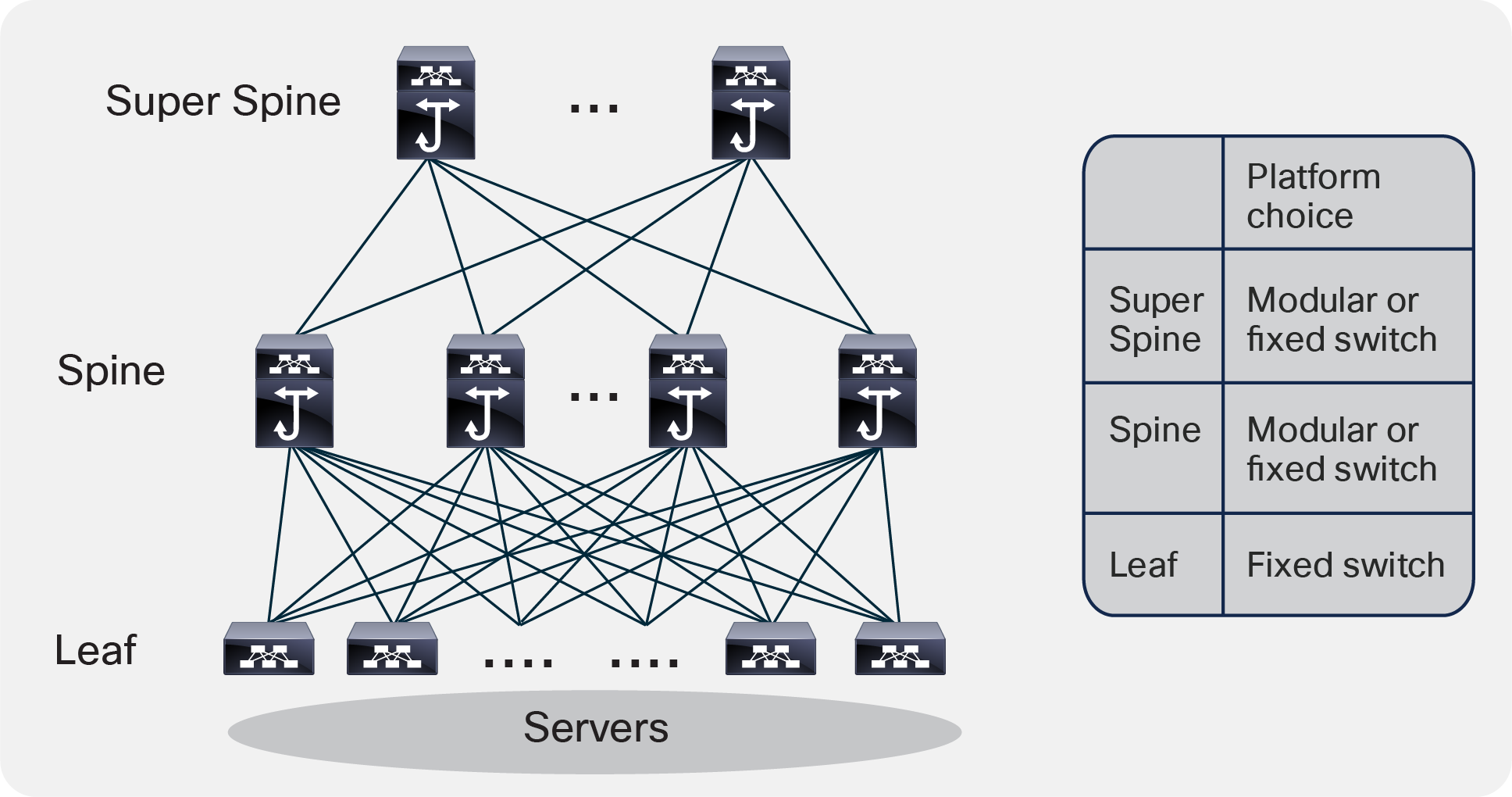
Three-tiered spine-leaf design platform choice
Nondisruptive data center network system maintenance best practices
For many years in the past, when organizations needed to do maintenance work for devices in the network, they had been using manual process to shut down the interfaces or reroute the traffic to alternative path by modifying routing metrics. Once the maintenance work is done, they need to reverse the changes manually to insert the device back into the data forwarding path. The manual process is time consuming and error-prone.
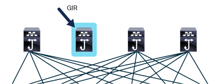
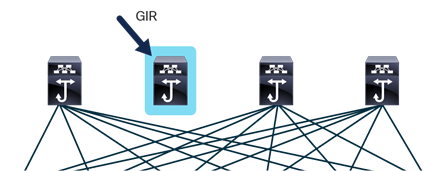
A few years back, Cisco introduced the Graceful Insertion and Removal (GIR) capability across multiple product lines, including the Cisco Nexus® data center switching product line. With GIR, you can easily isolate a network device (either a switch or a router) from the data forwarding path using automated procedure, with zero or minimal traffic loss. Then you can perform any kind of maintenance work on the device without impacting the application or services currently running. Once the maintenance work is done, you can easily re-insert the network device gracefully into the network with automated procedure again, without service impact.
GIR greatly reduces the overall maintenance window, and with deterministic behavior. For details on the GIR feature, please refer to the GIR configuration guide and white paper.[1]
Cisco Nexus switching products also support ISSU (in-service software upgrade), including enhanced ISSU, a capability that allows operators to upgrade the software image running on the switch to a different version. There is no data-traffic disruption because the data plane keeps forwarding traffic during ISSU. The control plane downtime is minimal. The ISSU support varies based on switch model and software version. Please refer to “ISSU Upgrade Matrix”[3] for the supported platform and ISSU upgrade path.
Since the introduction of Open NX-OS set of capabilities, NX-OS software running on Cisco Nexus switches can be patched for point fixes, assuming the software defect is patchable. The official feature name is called the Software Maintenance Upgrade (SMU) feature or patching feature. An SMU is a package file that contains fixes for a specific defect. In most cases, the software is patchable, but in certain cases such as hardware profile changes or kernel changes, the patching may not be practical. When available, software patching also can be a great way to perform maintenance for critical issues. Please note that an SMU is not issued for every defect; it is issued for some high-severity defects without a workaround, and for some PSIRT (product security incident response team) issues without a fix, etc. Once the fix is available in the new software, the customer is encouraged to pick up the fixes from the new software. For details on the SMU feature, please refer to the SMU configuration guide.
This white paper discusses data center system maintenance best-practice recommendations for some of the widely deployed data center network topologies using Cisco Nexus 9000 and 3000 series switches.
Virtual Extensible LAN (VXLAN) and Ethernet Virtual Private Network (EVPN) network
In the past few years, the enterprise on-premises data center network, enabled with Virtual Extensible LAN (VXLAN) Ethernet Virtual Private Network (EVPN) technology, became the de-facto design due to its many benefits: scalability, flexibility, being standards based, having a Layer2 overlay on top of a Layer3 underlay IP network, with any workload anywhere in the fabric (VMs, bare-metal servers, etc.) supporting both Layer2 and Layer3 multitenancy, etc. Figure 4 shows an example of a simple two-tiered VXLAN EVPN spine-and-leaf physical network design.
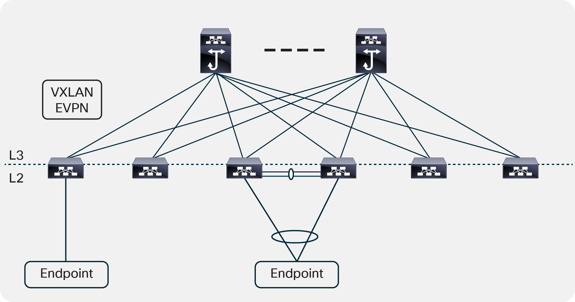
Two-tiered VXLAN EVPN spine-and-leaf network example
In this two-tiered VXLAN EVPN spine-and-leaf network, every lower-tier switch (the leaf layer) is connected to each of the top-tier switches (the spine layer) in a full-mesh topology. The spine layer is the backbone of the network and is responsible for interconnecting all leaf switches. Every leaf switch connects to every spine switch in the fabric. The underlay network between the leaf and spine switches is a Layer3 IP network running routing protocols of your choice; it provides Equal-Cost Multipath Routing (ECMP) for both east-west and north-south traffic. The overlay network runs a multipath Border Gateway Protocol (BGP) EVPN control plane to learn and distribute overlay-host and subnet information. There are two typical endpoint connectivity scenarios. Please note that the endpoint can be compute node or service node or storage node, etc.
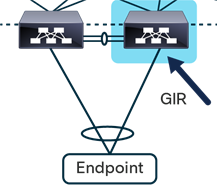
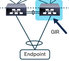
Scenario #1: The endpoint uses port-channel dual-home connecting to a pair of virtual Port-Channel (vPC) leaf VTEP switches.
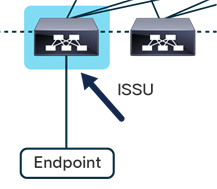
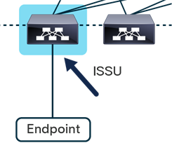
Scenario #2: The endpoint single-home connects to a single leaf VTEP switch. This is not a best-practice design, but some customers connect this way for various reasons.
Table 1 shows best-practice recommendations for system maintenance of spine and leaf switches in a VXLAN EVPN fabric.
Table 1. VXLAN EVPN network system maintenance best practices
|
|
System maintenance best practices |
| Spine layer switches Note: The spine switches can be Cisco Nexus® fixed switches or modular switches, running Layer 3 only in the underlay network. |
Use GIR to isolate the spine switch first, then perform maintenance work, including software upgrades. Note: For software upgrades, once the spine switch is isolated using GIR, the software can be upgraded directly to the target release using the default “install all nxos boot flash: nxos_software” command. Please check if EPLD image needs to be upgraded using “show install impact epld” command. |
| Leaf layer switches Note: It is best practice to use Cisco Nexus® fixed form factor switches in the leaf layer. |
Scenario #1: The endpoint uses port-channel dual-home connecting to a pair of vPC leaf VTEP switches.
Use GIR to isolate one of the vPC leaf switches first, then performs maintenance work, including software upgrades. Note 1: For software upgrades, once the vPC leaf switch is isolated using GIR, the software can be upgraded directly to the target release using “install all nxos bootflash: nxos_software” command. Please check if EPLD image needs to upgraded using “show install impact epld” command. Note 2: Software upgrades can also be done using enhanced ISSU or traditional ISSU, without using GIR. Scenario #2: The endpoint single-home connects to a single leaf VTEP switch.
Since the endpoint has only single connectivity to a single leaf VTEP switch, nondisruptive software upgrades can be achieved by either enhanced ISSU or traditional ISSU. Both traditional ISSU and enhanced ISSU enable nondisruptive data plane traffic during upgrade, the difference is how long the control plane is down during the upgrade. Please refer to the “ISSU Upgrade Matrix”[3] for the supported ISSU upgrade path. For other types of maintenance work on the leaf switch, the single home endpoint device traffic will be disrupted. One workaround is to migrate the endpoint content to a different endpoint before maintenance work. |
Spine-and-leaf Layer3 IP fabric
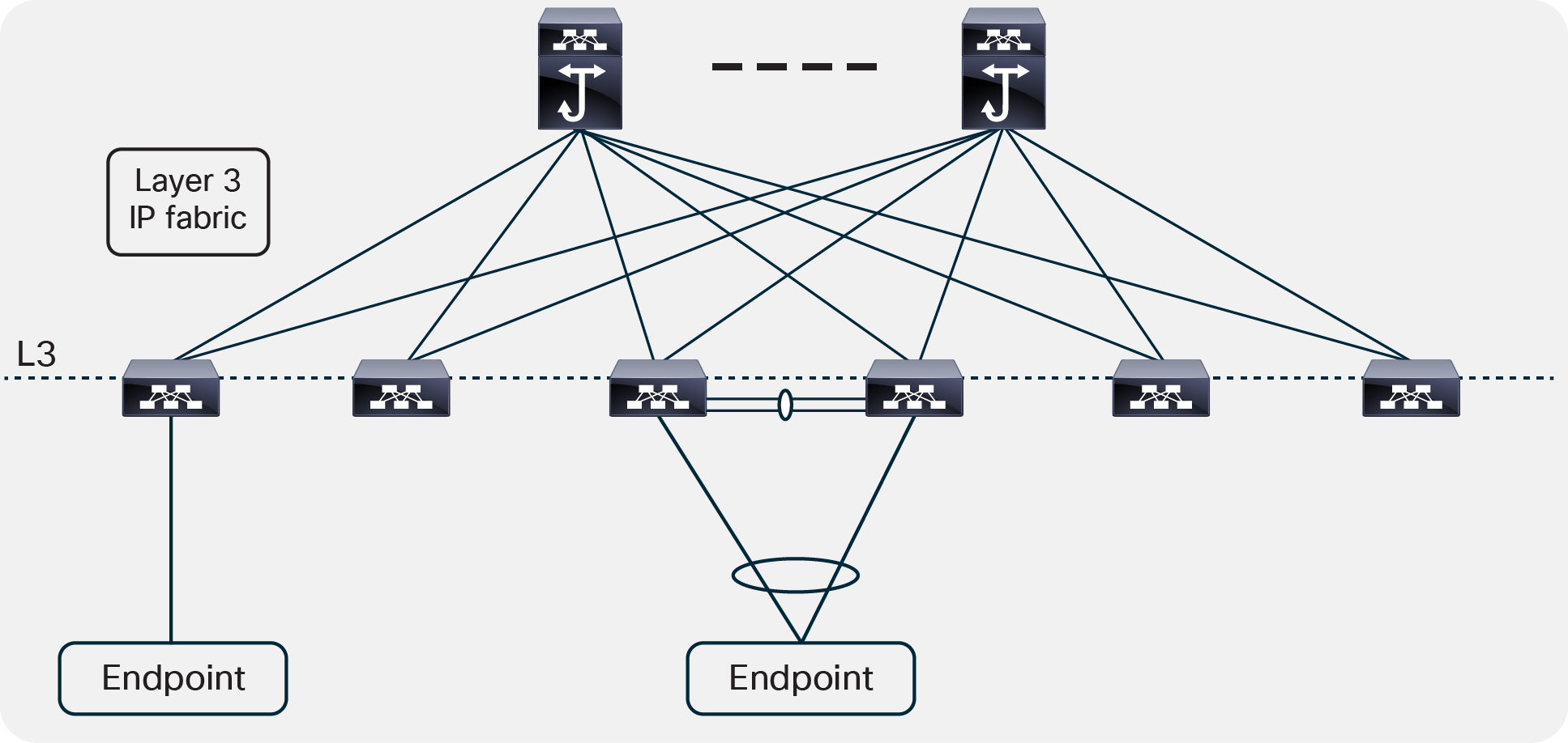
Spine-and-leaf Layer3IP fabric design has been the favorite design for large public cloud providers for many years, due to its many benefits: massive scalability, simplicity, resiliency, etc. Please refer to Cisco’s Massively Scalable Data Center Network Fabric White Paper[4] for more details. Enterprise customers can use similar spine-and-leaf Layer 3 IP fabric designs, though at a smaller scale for some use cases. Figure 5 shows a simple two-tiered spine-and-leaf Layer 3 IP fabric network design example.
Two-tiered spine-and-leaf Layer 3 IP fabric network example
In this two-tiered spine-and-leaf Layer 3 IP fabric network, every lower-tier switch (the leaf layer) is connected to each of the top-tier switches (the spine layer) in a full-mesh topology. The spine layer is the backbone of the network and is responsible for interconnecting all leaf switches. Every leaf switch connects to every spine switch in the fabric. There is no VXLAN VTEP enabled on leaf layer switches. The network connectivity between leaf and spine switches are Layer 3 IP network running BGP-only routing protocols or routing protocols of your choice. The leaf layer is responsible for advertising server subnets in the network fabric. Spine devices are responsible for learning infrastructure routes and end-host subnet routes.
There are two typical endpoint connectivity scenarios. Please note that the endpoint can be compute node or service node or storage node, etc.
Scenario #1: The endpoint uses port-channel dual-home connecting to a pair of vPC leaf switches.
Scenario #2: The endpoint single-home connects to a single leaf switch. There are some large public cloud providers deploying single-home servers for purposes of simplicity.
Table 2 shows the best-practice recommendations for system maintenance of a spine-and-leaf Layer 3 IP fabric.
Table 2. Spine-and-leaf Layer 3 IP fabric system maintenance best practices
|
|
System maintenance best practices |
| Spine layer switches Note: The spine switches can be Cisco Nexus® fixed switches or modular switches, running Layer 3 only in the underlay network. |
Use GIR to isolate the spine switch first, then perform maintenance work, including software upgrades. Note: For software upgrades, once the spine switch is isolated using GIR, the software can be upgraded directly to the target release using the default “install all nxos bootflash: nxos_software” command. Please check if EPLD image needs to be upgraded using “show install impact epld” command. |
| Leaf layer switches Note: It is best practice to use Cisco Nexus® fixed form factor switches in the leaf layer. |
Scenario #1: The endpoint uses port-channel dual-home connecting to a pair of vPC leaf switches.
Use GIR to isolate one of the vPC leaf switches first, then perform maintenance work, including software upgrades. Note 1: For software upgrades, once the vPC leaf switch is isolated using GIR, the software can be upgraded directly to the target release using the “install all nxos bootflash: nxos_software” command. Please check if EPLD image needs to be upgraded using “show install impact epld” command. Note 2: Software upgrades can also be done using enhanced ISSU or traditional ISSU, without using GIR. Scenario #2: The endpoint single-home connects to a single leaf switch.
Since the endpoint has only single connectivity to the single leaf switch, a nondisruptive software upgrade can be achieved using either enhanced ISSU or traditional ISSU. Both traditional ISSU and enhanced ISSU enable nondisruptive data plane traffic during upgrades; the difference is how long the control plane is down during the upgrade. Please refer to the “ISSU Upgrade Matrix”[3] for the supported ISSU upgrade path. For other types of maintenance work on the leaf switch, the single home endpoint device traffic will be disrupted. One workaround is to migrate the endpoint content to a different endpoint before maintenance work. |
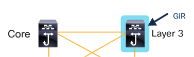
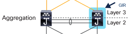
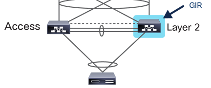
Traditional core, aggregation, and access network
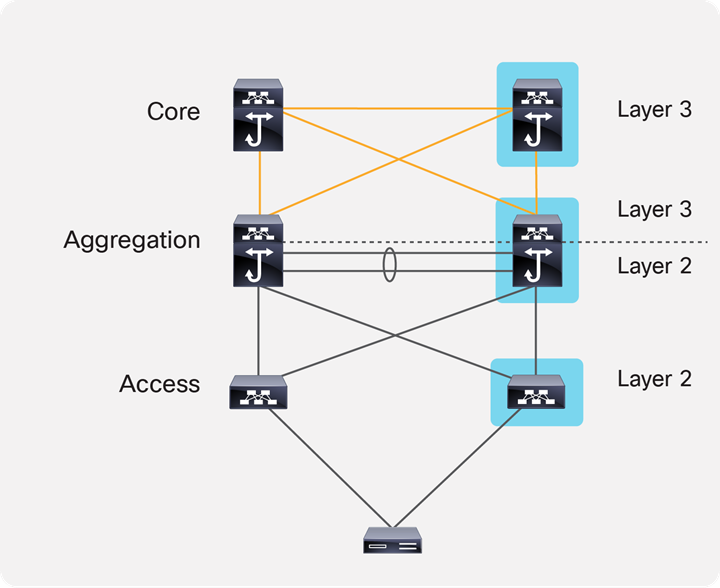
For customers who are using the traditional core, aggregation, and access network, a similar system maintenance methodology can be adopted. Figure 6 shows a traditional core, aggregation, and access network design example with a Cisco® double-sided vPC (virtual port-channel).
Traditional core, aggregation, and access design example
In this design, the pair of core layer switches is connected, using Layer 3 IP connectivity, to the pair of aggregation layer switches.
The pair of aggregation layer switches is connected with the pair of access layer switches using a Cisco double-sided vPC design. The aggregation layer switches act as the Layer 2 and Layer 3 boundary.
In the access layer, the server uses a Layer 2 port-channel connected to a pair of Layer 2 access switches enabled with Cisco vPC technology.
Table 3 shows the best-practice recommendations for system maintenance of a traditional core, aggregation, and access design.
Table 3. Traditional core, aggregation, and access design system maintenance best practices
|
|
System maintenance best practices |
| Core layer switches Note: The core layer switches can be Cisco Nexus® fixed switches or modular switches. |
Use GIR to isolate the core switch first, then perform maintenance work, including software upgrades. Note: For software upgrades, once the core layer switch is isolated with GIR, the software can be upgraded directly to the target release using the “install all nxos bootflash: nxos_software” command. |
| Aggregation layer switches Note: The aggregation layer switches can be Cisco Nexus® fixed switches or modular switches. |
Use GIR to isolate the aggregation switch first, then perform maintenance work, including software upgrades. Note: For software upgrades, once the core layer switch is isolated using GIR, software can be upgraded directly to the target release using the “install all nxos bootflash: nxos_software” command. Please check if EPLD image needs to be upgraded using “show install impact epld” command. |
| Access layer switches Note: It is best practice to use Cisco Nexus® fixed form factor switches in the access layer. |
The server uses port-channel dual-home connecting to a pair of vPC access switches. Use GIR to isolate one of the vPC access layer switches first, then performs maintenance work, including software upgrades. Note 1: For software upgrades, once the vPC leaf switch is isolated using GIR, the software can be upgraded directly to the target release using “install all nxos bootflash: nxos_software” command. Please check if EPLD image needs to be upgraded using “show install impact epld” command. Note 2: Software upgrades can also be done using enhanced ISSU or traditional ISSU, without using GIR. |
[1] Cisco Nexus 9000 and 3000 Graceful Insertion and Removal White Paper: https://www.cisco.com/c/en/us/products/collateral/switches/nexus-9000-series-switches/white-paper-c11-737899.html#_Toc462885403.
[2a] Cisco Nexus 9000 Series Switches installation and upgrading guides: https://www.cisco.com/c/en/us/support/switches/nexus-9000-series-switches/products-installation-guides-list.html.
[2b] Cisco Nexus 3000 Series Switches installation and upgrading guides: https://www.cisco.com/c/en/us/support/switches/nexus-3000-series-switches/products-installation-guides-list.html.
[3] ISSU Support Matrix https://www.cisco.com/c/dam/en/us/td/docs/Website/datacenter/ISSUmatrix/index.html.
[4] Cisco’s Massively Scalable Data Center Network Fabric White Paper https://www.cisco.com/c/en/us/products/collateral/switches/nexus-9000-series-switches/white-paper-c11-743245.html.