Passive Optical Networks: Cabling Considerations and Reference Architectures White Paper
Available Languages
Bias-Free Language
The documentation set for this product strives to use bias-free language. For the purposes of this documentation set, bias-free is defined as language that does not imply discrimination based on age, disability, gender, racial identity, ethnic identity, sexual orientation, socioeconomic status, and intersectionality. Exceptions may be present in the documentation due to language that is hardcoded in the user interfaces of the product software, language used based on RFP documentation, or language that is used by a referenced third-party product. Learn more about how Cisco is using Inclusive Language.

Cisco Certified Remanufactured Equipment for Networking
Upgrade at deeply discounted prices to help ensure secure network transformation.
Overview
● Purpose
◦ Enable end users and partners familiar with traditional Ethernet LANs to understand Passive Optical Networks (PONs)
◦ Explain Cisco’s and Panduit's position on PONs
◦ Describe PON components, application standards, considerations and guidance, and specification requirements
◦ Design
◦ Cabling
● Audience
◦ End users and partners who are new to PONs (including structured cabling)
◦ Existing PON end users and partners
● Deployment scope
◦ Large-scale deployments, such as campuses and high-rise buildings
● Outline
◦ Introduction
◦ Structured cabling elements for PONs
◦ Active elements for PONs
◦ Fiber cable management: Best practices
◦ PON power budget worked example
◦ Reference architectures (pros and cons)
◦ Commissioning/documenting and validating PON infrastructure
◦ Summary
Traditional LAN infrastructure deployed throughout enterprise and other markets has been highly effective at incorporating the growing domain of Ethernet devices into a unified infrastructure. These systems work best when end users need higher bandwidth and more flexibility across their systems, when user density is high, and when interoperability for future changes is paramount. However, when the end user has the goal of minimizing the space used for the telecom systems, when future retrofit or floor reconfiguration is not expected, and when there are long cable runs, alternative architectures and technologies can be considered.
Not all services, devices, and users truly require the full bandwidth that the traditional enterprise LAN can deliver. In fact, Microsoft’s recommendation for the modern enterprise to optimize cloud user experience is 500 Kbps per user. Aligning space, energy, and lifecycle costs with future network bandwidth requirements is possible by selecting the appropriate physical network architecture.
Many enterprise communication network owners and architects are increasingly interested in network design strategies that reduce energy consumption and shrink the bill of materials for nonrenewables deployed in network designs.
In addressing these issues, designers are looking for opportunities to reduce Operational Expenses (OpEx) in LANs, which are increasingly being called on to deliver voice, data, and video. These efforts tend to focus on reducing power consumption and cooling (in some cases).
Passive Optical Network (PON) design gives you the flexibility to right-size connectivity across the enterprise LAN – inside buildings and across an extended campus. These optical LANs align space, energy, heat, noise, radiation, and cost with your real bandwidth requirements, and can be highly effective at meeting customer needs.
In this white paper, Cisco and Panduit describe the critical components used in PONs and discusses network architectures to consider in an effective PON deployment.
Structured cabling elements for PONs
Fiber structured cabling
Historically, Point-to-Point (PtP) “unstructured” cabling has created many problems. In response, cabling standards such as TIA‐568/569 and ISO/IEC 11801 have recommended a hierarchical structured cabling infrastructure for connecting equipment.
Structured cabling is a comprehensive network of cables, equipment, and management tools that enables the continuous flow of data, voice, video, security, and wireless communications. Instead of PtP connections, structured cabling uses distribution areas that provide flexible, standards‐based connections between equipment, such as connections from Optical Line Terminals (OLTs) to closet distribution elements (splitters), horizontal distribution of cabling from closets, and zone-based Optical Network Terminals (ONTs) to copper user outlets.
Structured cabling is designed to meet Electronic Industries Association/Telecommunications Industry Association (EIA/TIA) and American National Standards Institute (ANSI) standards related to design, installation, maintenance, documentation, and system expansion. This helps to reduce costs and the risk of increasingly complex IT environments.
As an example of the value of structured cabling, some enterprise PON implementations employ ONTs in the work area (where they are accessible to users). This is classically distasteful to IT managers due to its availability for tampering, causing both security and reliability concerns. Of course, these concerns may be addressed in a number of ways: (1) installing the ONTs in a secured physical location (such as a locked datacom closet), (2) installing an eavesdropping detection system/alarm, and (3) installing the fiber-optic cable in some form of conduit (primarily in high-security applications).
Single-mode fiber
Standard single-mode G.652.D fibers (deployed widely in outside plant Gigabit Ethernet PONs (GPONs) can lose much of their signal by being bent too tightly, with potentially devastating effects on network performance.
Networking gear such as that used for GPONs deploys long wavelengths (1490 nm, 1557 nm, 1603 nm, etc.), where G.652.D class fibers are more bend sensitive and hence will benefit from bend-insensitive fibers. Also, next-generation GPONs may deploy even longer wavelengths with two to four times greater bending loss. This means that even if a link is operational today, fiber bending loss for next-generation technologies that use longer wavelengths could make the link unreliable in the future.
The need for smaller cable designs in enterprise PONs, with fewer fibers, cabinets, and enclosures and reduced overall space requirements, demands new fibers that are less bend sensitive than standard single-mode fibers meeting the G.652.D standard.
In response, G.657A1 optically “bend-optimized” single-mode fibers have been developed for use in bend-challenged inside plant applications such as optical LANs. Such fibers typically provide a 40% smaller minimum bend radius and 50% lower bend loss than their G.652 counterparts and enable components such as splitters and preterminated enclosures and assemblies to have a smaller footprint and be produced with higher yield (and at a lower cost).
Fiber cabling
In choosing fiber‐optic cables for an application, you should consider installation requirements as well as environmental and long‐term requirements. Installation requirements define how the cable will be pulled in conduits or placed in cable trays/conduits. Considerations for water ingress, temperature variation, tension (for aerial installations), etc. should be resolved to assure long‐term service in the designated environment.
You should contact cable manufacturers and share your requirements. Manufacturers will want to know the installation environment for the cable, fiber counts (consider “spares”), flame ratings, fiber types (multimode or single mode), maximum cable run, etc. and may recommend a “composite” cable (multimode fibers for today and single‐mode fibers that remain dark for tomorrow’s applications). The cable companies will evaluate your requirements and make suggestions before you seek competitive bids.
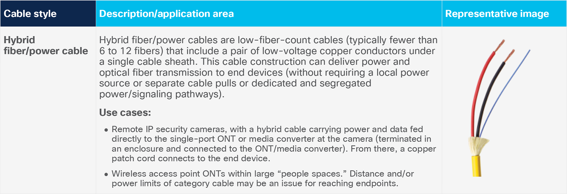
Table 1. Types of cables
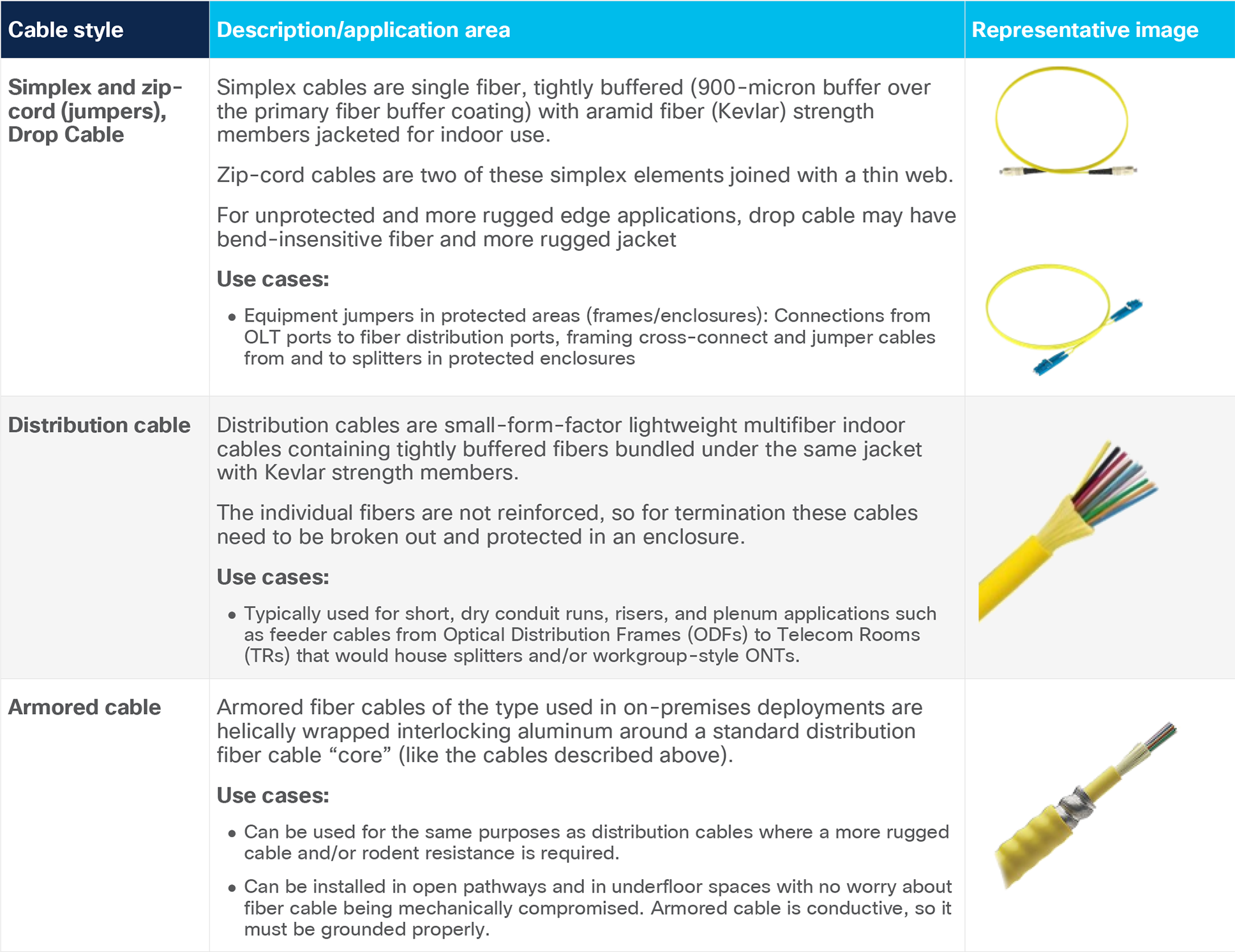
The cable plant design will call for a defined fiber count, and it may be advantageous to consider using composite cables which add- “spare” fibers to the build (terminated in panels but remaining “dark”). A few extra fibers add marginal cost compared with the labor and incremental cost of installing more cable (to mitigate against broken fibers during installation or connectors at distribution panels that get damaged through use).
Fiber connectors: Although dozens of fiber‐optic connectors have been deployed over the past 30 to 40 years, none have taken hold in optical LANs as much as the SC-APC and LC-APC connectors (SC = Subscriber Connector, LC = Lucent Connector, APC = Angled Physical Contact).
These are documented in the TIA Fiber Optic Connector Intermateability Standards (FOCIS) as FOCIS 2 and FOCIS 10, respectively.
Distribution elements: Rack-mount fiber enclosures house, organize, manage, and protect fiber‐optic cable, terminations, splices, connectors, and patch cords and provide logical representations of connectorized fibers on their front patching fields.
Wall-, ceiling-, and floor-mount zone enclosures: As an example, a very interesting architecture that enables a direct comparison with current closet-based workgroup switching is the “active zone” application (Fiber to the Enclosure or FTTE).
Many market verticals (education, military) do not necessarily desire another piece of electronic equipment (such as an ONT) to be placed on or about user workstations and prefer that such be installed in lockable enclosures. These “active zone” solutions save on CapEx by reducing copper horizontal installations because the horizontal cable lengths become predictable (and short) and may obviate the need for a significant number of closets. This approach is described in the TIA FOTC (Fiber Optics Technology Consortium) cost model available at FOTC.org.
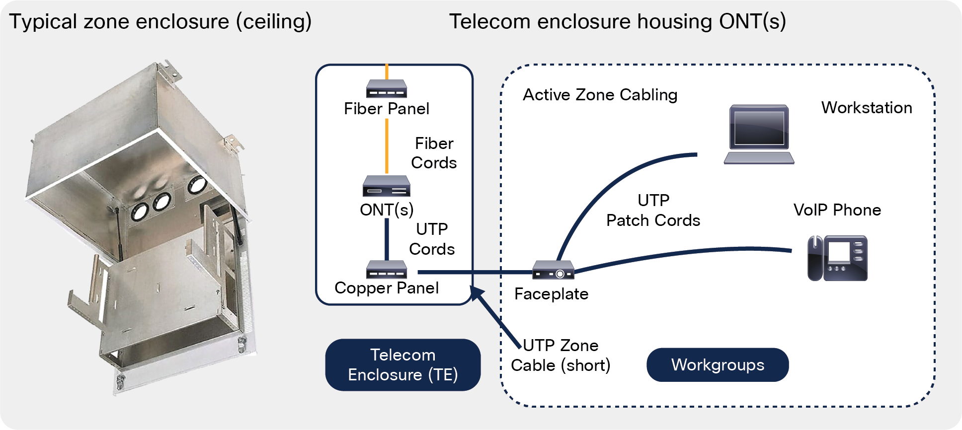
Zone cabling (ZDA) as a flexible/extensible fiber distribution element (example)
Zone cabling makes it easier to extend current and new technologies because moves, adds, and changes are handled at the zone enclosure and device endpoints.
Zone cabling solutions accommodate active gear (switches, ONTs) splitters, structured cabling components and can be used in floor-, ceiling-, and wall-mount applications while providing a complete end-to-end network solution.
Single-mode fiber cabling is terminated in a small patch panel inside the telecom enclosure and patched to the ONT(s) with fiber patch cords. Short runs of copper cabling are terminated in the enclosure in a patch panel and run to end-user outlets.
Zone enclosures
Each zone enclosure serves as a cabling distribution point for a particular zone, increasing network flexibility, manageability, accessibility, and efficiency. Using a distributed network and a zone cabling topology for your physical infrastructure can solve telecommunication room congestion. In addition, PON fiber backbone cables to the zone enclosures extend the reach of your network beyond copper limitations.
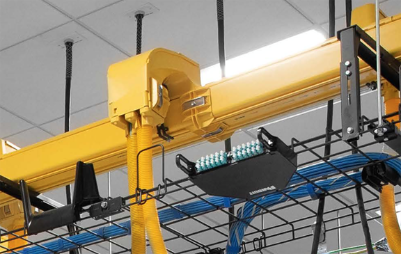
Pathways: The primary value of pathways in an optical LAN is to provide functional, protective containment for the structured cabling infrastructure in an often dense cabling environment (near the headend). Pathways that are versatile and accessible accommodate growth and change and protect cables from physical damage.
ANSI/TIA‐569 “Commercial Building Standard for Telecommunications Pathways and Spaces” contains reference methods for separating and routing data cables in overhead, underfloor, and conduit cable routing applications.
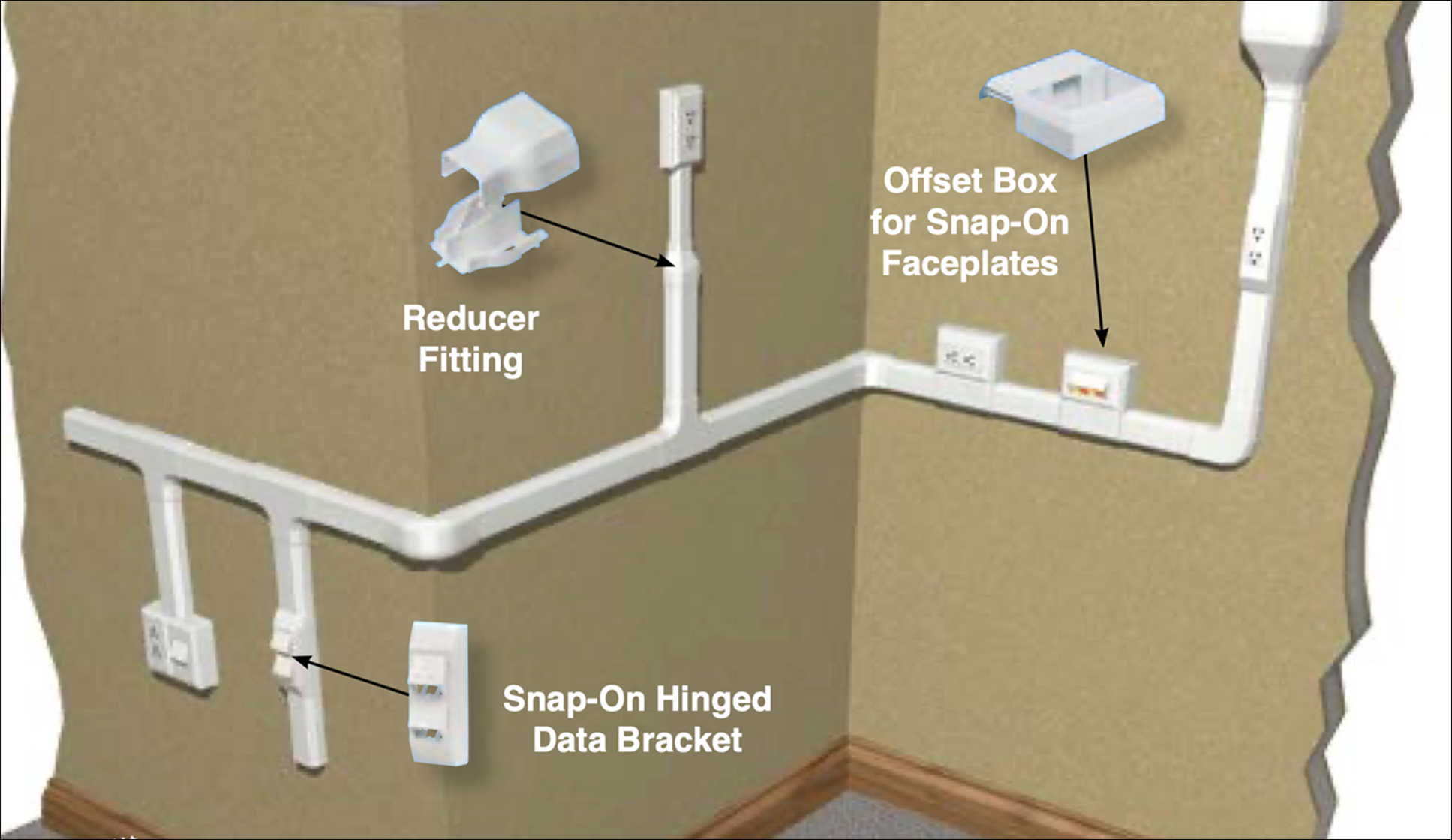
Surface raceway roadmap for UTP (and fiber) cabling systems
Once cable pathways are in place, attention can be directed to placing the cables in the pathways. Fiber cable bundling strategies have been developed to effectively and neatly route cables through pathways; retain flexibility for operators to make frequent moves, adds, and changes; and not obstruct airflow. These strategies include the use of cable ties and pathway accessories that protect and manage high‐performance copper and fiber cabling, in accordance with TIA/EIA‐568 and GR‐1275‐CORE Section 13.14, in order to maintain network integrity. Cable ties and accessories must be operator safe without protruding sharp ends or edges that can potentially cut or abrade cables. Plenum‐rated cable tie designs are required for cable bundling within air-handling spaces such as ceiling voids and underfloor areas, in accordance with National Electrical Code (NEC) Section 300‐22 (C) and (D).
The key capacity planning issue is an accurate estimation of cable count and volume in order to specify pathway size. For initial deployments, maximum fill should be 25% to 40% to leave room for future growth. A calculated fill ratio of 50% to 60% will physically fill the entire pathway due to spaces between cables and random placement.
Equipment and telecom room fiber and copper pathways
Most vendors of pathways offer online fill calculator tools that can help you determine the size of pathway needed for a specified cable quantity and diameter.
Splitters: Optical splitters are highly reliable passive power-splitting elements that are based on planar light-wave circuit (PLC) technology. They are available in a variety of split ratios, including 1:4, 1:8, 1:16, 1:32, 1:64, etc., and come in several different form factors such as a “bare” PLC splitter (without connectors), preterminated fan-out variations (with LC-APC, SC-APC, and multifiber push-on [MPO] connectors), 1RU rack-mount splitters, and modular cassette-style splitters.
Cisco Catalyst GPON
The Cisco and Panduit approach to PONs allows organizations to evolve their LAN in a gradual and cost-efficient way, using the same access node and in-building cabling, while making minimal changes in electronics today and going forward (to new generations of PON). Perfect for long-distance simple network connectivity requirements, the market-leading capabilities of the Cisco Catalyst™ PON Series enables organizations to achieve:
● Lower OpEx (savings in power, floor space, and centralized management, 3-year warranty, no license fees)
● Long-term value with fixed architecture over generations of PONs
● Secure communication with a fiber-based infrastructure
The Cisco Catalyst GPON solution is based on the CGP-OLT and the CGP-ONT coupled with Cisco® PON Manager, which presents an innovative and comprehensive solution for enterprise fiber networks.
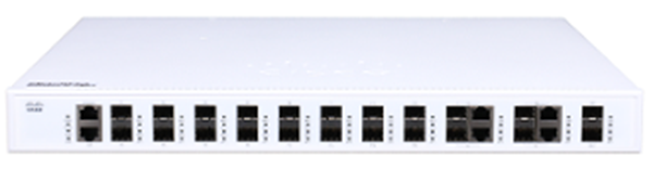
Cisco Catalyst PON OLT platform
The CGP-OLT is a centralized 1-Rack-Unit (1RU) access point for the entire LAN, capable of serving from hundreds to thousands of users and devices. It has market-leading capacity: up to 108-Gbps switching capacity, up to 95-Mpps forwarding capacity, and a reach of up to 20 km to ONT endpoints. The CGP-OLT supports GPON to give every user Gigabit speeds today and can smoothly evolve to next-generation fiber technologies to meet the demands of tomorrow with minimal or no change to the physical cable plant.
The CGP-OLT is available in two sizes (the 8T and larger 16T) suitable for all types of deployments: office buildings, large enterprises, military bases, hotels and resorts, hospitals, large campus applications, sports venues, or any other environment requiring a LAN.
Table 2. Cisco Catalyst PON OLT lineup
| Model |
CGP-OLT-8T |
CGP-OLT-16T |
|
|
|
|
| PON ports |
8 GPON ports |
16 GPON ports |
| Ethernet uplink ports |
4x 1G combo ports (copper RJ-45 + SFP optical) and 2x 10G SFP+ ports |
4x 1G combo ports (copper RJ-45 + SFP optical) and 2x 10G SFP+ ports |
| Optical connectivity |
SC APC |
SC APC |
| Endpoints supported |
1024 |
2056 |
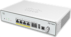
Cisco Catalyst PON ONTs
Cisco optical network terminals are the user access points controlled by the OLT. The Catalyst ONT family delivers superior services with high bandwidth to every user.
The variety of ONTs meets every need: they can be deployed in a variety of locations and support wired and wireless Gigabit connectivity, Power over Ethernet (PoE), and a selection of user interfaces.
Table 3. Cisco Catalyst PON ONT lineup
| Desktop ONT models |
Gigabit ethernet ports |
Plain old telephone service (POTS) ports |
CATV ports |
|
| CGP-ONT-1P |
|
1 PoE+ |
– |
– |
| CGP-ONT-4P |
|
4 PoE+ |
– |
– |
| CGP-ONT-4PV |
|
4 PoE+ |
2 (RJ-11) |
– |
| CGP-ONT-4PVC |
|
4 PoE+ |
2 (RJ-11) |
1 coax |
| Wireless ONT (5 GHz/2.5 GHZ) models |
Gigabit ethernet ports |
POTS ports |
CATV ports |
|
| CGP-ONT-4TVCW-x* |
|
4 |
2 (RJ-11) |
1 coax |


Fiber cable management: Best practices
Improperly routed or unprotected fiber‐optic cable is susceptible to various types of damage. Crushing, pinching, or micro‐bending can result in impeded signal transmission and cable breakage. Bend radius violations, or macrobending, in fiber‐optic and copper cables can increase attenuation, affecting overall system performance and causing fatigue leading to long‐term signal failure.
Fiber cables are at risk of being damaged and can result in service interruption and downtime. Identifying, testing, removing, and replacing a damaged cable is costly in terms of labor and network service interruptions. A properly designed and installed cable routing system carries cabling along a logical route to minimize bends and optimize cable lengths while providing easy access to make moves, adds, and changes.
Cable management plans may involve greenfield fiber cable build in a new facility or a “forklift” or incremental upgrade of fiber cabling in an existing facility:
● For existing facilities being upgraded with a PON, it is imperative to evaluate existing cabling and to document the present fiber infrastructure thoroughly (TIA 606 labeling and identification provides guidance here).
● Document current and projected network architecture using Microsoft Visio, Excel, or the like (vertical market software is available specifically for this task).
● Document equipment interfaces in the same way with relation to current and projected needs, and similarly for various current and projected cable types and port counts present, and approximations of routed distances to distribution areas and equipment.
● Develop a plan to accommodate future growth. Build flexibility into the distribution and patching elements, such that cross‐connect patching will allow “any‐to‐any” connections. This allows for ultimate flexibility for meeting current and future device needs within the facility.
Higher fiber cable count requirements, enhanced performance demanded from fiber solutions, and longer distances required (campus networks) as applications grow have placed strain on IT organizations, which may require miles of cable infrastructure for interconnecting servers, and storage in multiple buildings for optical LAN fabrics.
Unfortunately, many organizations have chosen the reactionary and incremental cabling approach of traditional point-to-point interconnect, deploying fiber cables singly to satisfy immediate needs. The resulting cable chaos impedes intelligent, rational growth and contributes to an ineffective growth strategy that only deteriorates over time.
Splitter positioning
Because of the many options for ceiling, floor, wall, Main Distribution Frame (MDF), or Intermediate Distribution Frame (IDF) optical splitter placement, one can completely exit, and eliminate, the telecommunications closet. This is not always the case, but there are situations where building architects can take advantage of this ability.
One can also choose centralized (close to or in the equipment room), distributed (pushed out deep in the network/building) or cascaded splitters (for example, a 1×4 splitter that connects 1×8 splitters), depending on fiber availability and space constraints in the building’s cable risers, horizontal space, pathways, and drops.
Splitter split ratio
Optical splitters can be designed in ratios from 1×2 to 1×64 (given appropriate power budgeting). Now more than ever you can match actual bandwidth requirements with the optical split ratio.
For example, when designing for the Internet of Things (IoT) and smart building device connectivity, one can deploy a high 1×64 split ratio. And for deploying high-bandwidth devices, such as IP cameras and wireless access points, one can use a low 1×8 split or 1×16 split in order to dedicate more bandwidth to the services, users, and devices that truly need the extra capacity.
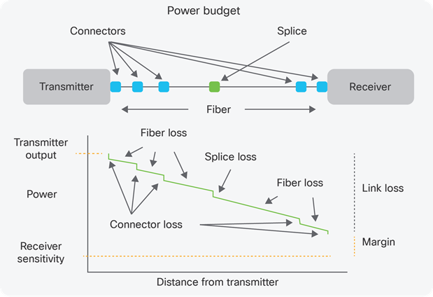
PON power budgeting and reach limitations
The single largest contributor to the power budget in PON links is the power splitter.
Preterminated optical splitters using PLC technology have optical loss intrinsic to the splitter technology itself (excess loss), have a loss associated with power splitting (theoretical or splitting loss), and have loss associated with the mating of connectors (insertion loss) such that the value used in power budgeting is the sum of these three components.
Total loss = Excess loss + Splitting loss + Connector insertion loss
Where the splitting loss (the largest contributor to total loss) is:
SL = -10log10(1/n); n is the number of split legs
So for a 1x64 splitter, SL = -10log10(1/32) = 15 dB
The table below lists the losses for typical PLC splitters that are commercially available.
Table 4. Total loss tabulations for commercially available PLC splitters
| Insertion loss (per FOTP 180) |
1x2 |
1x4 |
1x8 |
1x16 |
1x32 |
| 4.2 dB |
8.0 dB |
11.5 dB |
14.7 dB |
18.5 dB |
|
| 2x2 |
2x4 |
2x8 |
2x16 |
2x32 |
|
|
|
|
11.7dB |
15.0 dB |
19.0 dB |
PON power budget worked example
This example consists of a large PON deployment in a 50-story high-rise building (with many endpoints and users) using a “centralized fiber” approach with splitters deployed in an equipment room cross-connect and remotely in floor-by-floor telecom rooms. (Refer to Figure 4 for the cabling elements involved in this scenario.)
For short-reach links like those presented in optical LAN applications, the dominating source of optical loss is from splitters, fiber connectors, and the fiber itself (in that order). In longer-reach links using single-mode fiber, designers and planners are concerned with dispersion-related power penalties (polarization mode dispersion or PMD), which are not a concern for PON designs.
PON scenario
● OLT GPON port (28 dB power budget) in Equipment Room (ER).
● Local equipment patch panel (SC APC in same rack).
● ODF cross-connect adjacent to framed OLTs; the OLT side of the cross-connect frame has smaller optical splitters to zoned closets (1x4), and the “customer side” is connected to riser cabling to multiple Telecom Rooms (TRs).
● Cascaded splitters in TRs (1x16) connected to Telecom Enclosures (TEs) or zone boxes (these are defined in TIA-569, Pathways and Spaces).
● ONTs in zone boxes have small local equipment patch panels with jumpers to ONTs.
● Worst-case end-to-end cable run length (end-to end cabling running from ER to furthest zone enclosure on top floor): Per TIA, the maximum distance for single-mode fiber in a building between main and intermediate cross-connects is 8200 feet, while the maximum intermediate-horizontal distance is 1640 feet. For this scenario we will assume an end-to-end single-mode channel of 1500 feet.
Elements of the power budget:
● Total cable attenuation = 1500 ft x 1.0 dB/km = 0.46 dB (include all linear cabling, jumpers, and splitter attenuation)
● 1x4 splitter input mated connector pair (SC APC) = 0.75 dB
● 1x4 splitter total loss = 8.0 dB
● Cross-connect mated connector pair (SC APC) = 0.75 dB
● 1x16 splitter input mated connector pair (SC APC) = 0.75 dB
● 1x16 splitter total loss = 14.7 dB
● ONT zone enclosure patch panel mated pair = 0.75 dB
The total end-to-end fiber cabling system loss sums to 25.9 dB, which is inside of the GPON application power budget of 28 dB. Consideration should be given to the operating margin in this case, which is 2.1 dB (28 dB minus 25.9 dB). This may be too tight for the long-term reliable operation of this network in the face of transmitter optical output power degradation over time and the operational issues associated with moves, adds, and changes (read this as dirty fiber connectors).
In this case it may be prudent to replace the 1x16 splitters in the TRs with two 1x8 splitters for each, thereby doubling the number of OLT GPON ports dedicated to each TR. If this is done, 3.2 dB is given back to the power budget, netting a new margin of 5.3 dB.
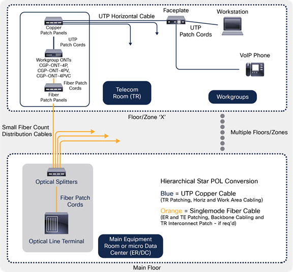
Traditional hierarchical star architecture
This design includes the following structured cabling elements:
● Main equipment room housing routing and core/aggregation switching
● Multiple telecom rooms with workgroup switches connected to ER switches with multimode fiber (MMF) (typically) riser backbones
● Multiple workstation outlets connected to user devices with Unshielded Twisted Pair (UTP) horizontal cabling
● Permanent (testable) structured cabling links in fiber (orange) and copper (blue)

Hierarchical star architecture cabling
Table 5. Pros and cons of hierarchical star architecture
| Pros |
Cons |
| Repeatable and well-known architecture with vast support in structured cabling ecosystem (suppliers, designers, systems integrators, contractors, etc.) |
Expensive to scale to thousands of endpoints. OpEx (power) tends to be higher (than optical LAN designs). |
| Centralization of workgroup switching to closets in racks makes it easy for IT to troubleshoot and manage switching and cabling systems. |
Horizontal cabling may have reach limitations (future proofing for new data rates), and architecture requires telecom rooms/closets to reach all users. |
| PoE options without local power or “hybrid” cabling systems (power can be centralized to closets and drive endpoints). |
Testing/commissioning of two separate cable plants (fiber backbones and UTP horizontal) is labor intensive. |
Suitable architectures for optical LAN
Brownfield – “minimally invasive”: Redeploy existing horizontal cabling infrastructure with a vision toward a complete optical LAN or future incremental upgrades of optical LAN.
This design includes the following structured cabling elements:
● Main equipment room housing routing and OLTs
● Multiple telecom rooms with workgroup or multiple smaller ONTs connected to ER OLT(s) with Single-Mode Fiber (SMF) (typically) riser backbones and optical splitters (deployed in ER or TRs)
● Multiple workstation outlets connected to user devices with category copper horizontal cabling
● Permanent (testable) structured cabling links in fiber (orange) and copper (blue)
Use of existing horizontal cabling
Table 6. Pros and cons of using existing horizontal cabling
| Pros |
Cons |
| No change to existing UTP horizontal cabling infrastructure saves cost in incremental OLAN upgrade |
Can be expensive per port if a large number of endpoints and telecom rooms do not already exist |
| Centralization of ONTs to closets in racks or enclosures makes it easy for IT to troubleshoot and manage ONTs and cabling systems |
Horizontal cabling may have reach limitations (future proofing for new data rates), and architecture requires telecom rooms/closets to reach all users |
| PoE native to ONTs can be centralized to closets and drive endpoints |
Incremental testing and commissioning of new fiber backbones |
| Other services in closets (POTS infrastructure, for example) is maintained in closets |
Splitters in ER limit future flexibility in infrastructure moves, adds, and changes |
| Future ready for conversion to PON (could be a mix of closet and zone-based deployment of ONTs) |
More individual permanent links (copper and fiber) to test and troubleshoot |
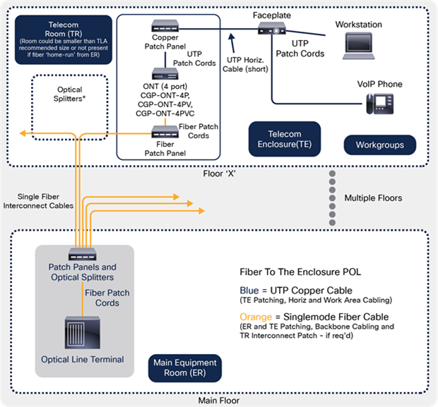
Greenfield – FTTE (Fiber to the Enclosure), zone-based ONTs: Preferred approach
This design includes the following structured cabling elements:
● Main equipment room housing routing and OLTs
● Telecom enclosures with small ONTs connected to ER OLT(s) with SMF (typically) riser backbones and optical splitters (deployed in ER or TRs)
● TRs used as cable “pull-through” points and possible remote power for ONTs
● Multiple workstation outlets connected to user devices with category copper “zone” cabling
● Permanent (testable) structured cabling links in fiber (orange) and copper (blue)
FTTE cabling
Table 7. Pros and cons of FTTE cabling
| Pros |
Cons |
| Flexible and extensible network architecture (cable plant to closets will not change over PON speed bumps) |
ONT zone deployment requires local power (in or near the multiple zone enclosures) or hybrid fiber/copper cables to deliver PoE to endpoints |
| Reach limitations native to copper horizontal are mitigated and the use of lower-rated UTP is possible for the short zone cabling runs |
IT personnel do not prefer “decentralized” management/troubleshooting of electronics and cabling systems (prefer telecom closets) |
| Easier testing of infrastructure (point to multipoint) and no testing of UTP horizontal (if pretested zone cords are deployed) |
Zone enclosures may not be appropriate and may present design-in challenges depending on environment (accessibility, for example) |
| Replacing closet-based with zone-based distribution saves both CapEx and OpEx (for larger installations) |
Depending on heat dissipation and deployment environment for ONTs, enclosures may need to be environmentally controlled |
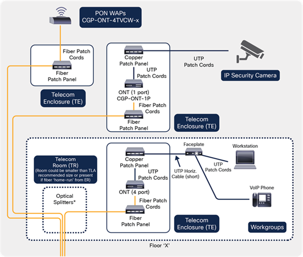
Single-endpoint device support: One-port ONT supporting building automation systems, IoT devices, or IP cameras
This design includes the following structured cabling elements:
● Shown as “overlay” to existing PON
● Zone enclosures (TEs) provide demark and testable links for devices (IP cameras, building automation systems, and wireless APs)
● At long reach, powering these devices with TR-based power may be impractical (solution: local power or remote “pulsed power”)
● Depending on environment, cabling systems and enclosure may have to be environmentally hardened or OSP-rated
● Multiple PON wireless APs and/or IP security cameras can be served by correct sizing of TEs and supporting cable plant
Cabling for single-endpoint device support
Table 8. Pros and cons of single-endpoint device cabling
| Pros |
Cons |
| Long reach of SMF and generous PON power budget place few limitations on positioning of endpoint devices |
Depending on heat dissipation and deployment environment for ONTs (outside plant, for instance), enclosures may need to be environmentally controlled and/or “hardened” |
| Reach limitations native to copper horizontal are mitigated, and the use of lower-rated UTP is possible for the short zone cabling runs to camera or PON wireless AP endpoints |
At long reach, powering these devices with TR-based power may be impractical (alternate and emergent solutions like pulsed power may have to be evaluated) |
| Mixed environments supporting workstations, wireless, and building automation systems may be unified under one network |
Hardened pathways or more rugged fiber cabling systems may have to be considered for horizontal cabling to exposed PON wireless APs |
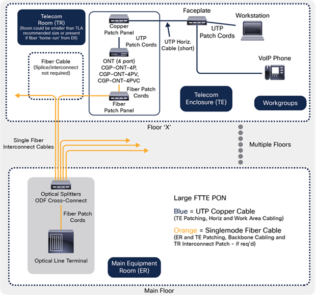
Large PON deployment (many endpoints): Centralized fiber/splitters with cross-connect
● Main equipment room housing routing, OLT(s), ODF, and splitters
● Splitters in ER are deployed in ODF(s) as port-mapped to GPON ports in OLT and ready to cross-connect to provision ONTs downstream
● Large-fiber-count SMF cables leave the cross-connect ODF and transit to TRs and/or TEs housing ONTs
● Multiple workstation outlets connected to user devices with category copper “zone” cabling
● Permanent (testable) structured cabling links in fiber (orange) and copper (blue)
Cabling for large PON deployment
Table 9. Pros and cons of cabling for large PON deployments
| Pros |
Cons |
| Most flexible/extensible network architecture (cable plant to closets will not change over PON speed bumps, and management from centralized ODF yields greatest flexibility) |
More vertical cable runs with higher fiber counts to TRs or TEs. Higher initial total installed cost with equipment room cross-connect ODF |
| Reach limitations native to copper horizontal are mitigated, and the use of lower-rated UTP is possible for the short zone cabling runs |
ONT zone deployment requires local power (near the zone enclosures) or hybrid fiber/copper cables to deliver PoE |
| Isolation and partitioning of risk is mitigated by separating and controlling provisioning of zones (TRs or TEs) in a centralized fashion in the ER |
IT personnel do not prefer “decentralized” management and troubleshooting of electronics and cabling systems (prefer TRs) |
| Splitters can be cascaded – small ER ODF splitters and larger splitters deployed in TRs or TEs) yields customized deployment based on bandwidth requirements |
|
Commissioning/documenting and validating PON infrastructure
Testing PONs is different from testing other on-premises cabling networks, which use fiber optics. PONs use single-mode fiber, while centralized fiber (FTTD) and backbones supporting hierarchical star networks are generally implemented in multimode fiber. PONs use a single fiber transmitting bidirectionally in different wavelengths and deploy optical splitters in the network. Splitters add substantial loss to the channel and can cause confusion when tested with an Optical Time Domain Reflectometer (OTDR). Multiple cascaded splitters must be considered when creating a loss budget to compare against test results.
After PON cabling is installed, testing must be performed from end to end. The end-to-end loss includes the connectors on each end, the loss of the fiber in each link, the insertion loss of the connectors or splices, and the loss of the splitter itself (which may include connectors). You must measure total loss from the OLT to the ONT at all operating wavelengths and bidirectionally to assure transmission modes of the channel.
Panduit recommends the use of Tier I testing (Optical Loss Test Set, or OLTS) as the benchmark method to measure end-to-end or permanent links against a preestablished and known loss test limit. This is the method that is generally expected for acceptance against warranty for fiber (and copper) structured cabling suppliers. Note that not all OLTS units have sufficient dynamic range to test through splitters, and this must be verified before using existing units or purchasing new ones for this purpose.
As with all fiber-optic links, troubleshooting (with a Tier II device such as an OTDR) requires knowledge of the system, expected link losses (loss budget as calculated in the large PON deployment scenario described earlier in this paper) and optical signal levels, and typical problems that may be encountered (such as difficult pathways and potential bending areas of the cable). Inspection and cleaning of connectors must be a core competence of those doing troubleshooting and remediation, as studies indicate that this is disproportionally the largest source of fiber link failures.
OTDR testing from the user (ONT) end is recommended, as this presents the easiest trace interpretation. Testing from the headend OLT, the OTDR sees and adds together the backscatter traces from all the fibers. As a result, it becomes impossible to see detail on individual fibers, and loss events cannot be easily assigned to any individual fiber unless the cable plant is carefully documented at installation.
For detailed information on field test best practices for fiber cabling systems, visit: https://www.panduit.com/content/dam/panduit/en/solutions/NI-DC-PN445-ENG.pdf
For detailed information on inspection and cleaning best practices for fiber-optic connector systems, visit: https://www.panduit.com/content/dam/panduit/en/products/media/7/07/507/2507/109902507.pdf
Extending fiber connectivity using a passive optical network, inside buildings and across a campus, is best when customers expect high port counts with relatively lower user density and long cable runs. This architecture allows enterprise LANs to realize the benefits of fiber cabling, including low lifecycle costs, reduced real estate used for telecommunications infrastructure, and room to upgrade without updating the cabling infrastructure.
ONTs can be deployed in a wide variety of mounting choices, such as wall, floor, ceiling, desk, and furniture, that allow for flexibility, modularity, and easy infrastructure moves, adds, and changes.
Initial implementation of GPON ONTs with a properly designed and specified structured cabling system will allow for graceful migration to 10G XGS-PON if required (with no or minimal change to the cable plant). This is important, as it allows for cost-effectively focusing GPON ONTs for <1 Gbps connectivity for IoT and smart building applications. Conversely, it also allows for future symmetrical 10G ONTs (to be added strategically when needed only where >1 Gbps capacity is truly needed, perhaps for wireless APs).
This means that bandwidth can be exactly matched at the endpoints to the enterprise service, user, or device requirements. This is a far more efficient and “migratable” network design that traditional LAN architecture can’t replicate (without significant infrastructure and cabling changes).
A structured cabling approach to PON infrastructure design yields the following value vs. an unstructured approach (with PtP cabling):
● Design and specification: Testability of the permanent link segments (copper and fiber) in the reference designs can provide assurance for commissioning new ports and may yield potentially longer warranty terms.
● Network longevity (future ready): Designed-in spare ports (no need to pull new cables for adds) and fiber backbones with higher-grade single-mode fiber (vs. MMF or copper).
● Maintainability (moves, adds, and changes): In environments with multiple changes occurring, it is advantageous to centralize, such as in an ER, TR, or TE, to mitigate risk and minimize costs (backbone links are largely untouched during infrastructure changes).
● Installation: Planning for cable slack is not required when permanent links are built in the field (ER to TE, ER to TR, and TR to TE).
For more information
For more information, please contact Cisco at: https://www.cisco.com or Panduit at https://www.panduit.com/ or https://www.panduit.com/panduitciscoalliance.
About Cisco
Cisco (NASDAQ: CSCO) is the worldwide leader in networking that transforms how people connect, communicate, and collaborate. Information about Cisco can be found at: https://www.cisco.com.
For ongoing news concerning Cisco, please visit: https://newsroom.cisco.com.
About Panduit
Panduit is a world leader that engineers flexible, end-to-end electrical and network connectivity physical infrastructure solutions that help businesses stay connected in a global world. Our high-performance products improve productivity and offer a lower total cost of ownership to create a competitive business advantage. Strong alliances with industry leaders, a global staff, and unmatched service and support make Panduit a valuable, trusted partner.
For the latest news on Panduit, please visit our media resource page at https://www.panduit.com/en/about/media-resources.html.
