Catalyst 9300 Stackwise System Architecture White Paper
Available Languages
Bias-Free Language
The documentation set for this product strives to use bias-free language. For the purposes of this documentation set, bias-free is defined as language that does not imply discrimination based on age, disability, gender, racial identity, ethnic identity, sexual orientation, socioeconomic status, and intersectionality. Exceptions may be present in the documentation due to language that is hardcoded in the user interfaces of the product software, language used based on RFP documentation, or language that is used by a referenced third-party product. Learn more about how Cisco is using Inclusive Language.
The network access model in the enterprise campus has evolved significantly from basic user connectivity to an intelligent, powerful, and high-speed building block. Security, cloud, mobility, and the Internet of Things (IoT) in enterprise networks have been driving the network toward major innovations. Cisco® Catalyst® 9000 software and hardware have been designed to address these current and future demands.
Wireless technology is the industry’s new megatrend, and it presents a multidimensional challenge to enterprise IT organizations. This swiftly growing technology, with exponentially increasing numbers of mobile devices with high-performance demands, is rapidly changing the landscape of network infrastructure and its reliability. IT requires a reassessment of traditional network models and assembly of network designs that can respond with a broad set of evolutionary architectures. Stacking provides an opportunity to use a pay-as-you-grow model to meet these demands.
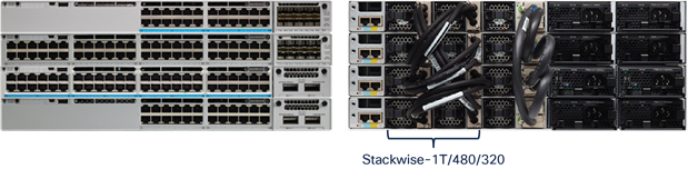
As the wired and wireless Gigabit evolution begins at the access layer, user and application demands will increase to high-speed, low-latency data switching for optimal performance. Cisco has built a system architecture to support such innovations. The Cisco Catalyst 9000 family of switches were developed to meet these demands. The Cisco Catalyst 9000 family is completely revamped with modular Cisco IOS® Software (Cisco IOS XE) and a flexible Application-Specific Integrated Circuit (ASIC), called the Cisco Unified Access® Data Plane (UADP), with an x86 CPU to handle the future needs of the network. Cisco Catalyst 9300 Series Switches with Cisco StackWise®-1T,Cisco StackWise®-480 and StackWise®-320 offer platform, software, and network resiliency at the access layer. The 9300 Series is the industry’s highest-density stacking bandwidth solution with flexible uplink architecture. This white paper talks in detail about the benefits and architecture of StackWise-1T, StackWise-480 and StackWise-320.
The StackWise architecture allows stacking of up to eight switches in a ring topology to achieve 1T, 480G or 320G of stack bandwidth. The stacking architecture expands form factor, switching capacity, port density, and redundancy as well as providing a single control plane. This architecture provides resiliency, scalability, and central management. The latest Cisco Catalyst 9300 Series Switches support StackWise-1T/480/320. This technology is flexible, modular, and evolutionary, and it delivers Cisco IOS XE feature capabilities with hardware acceleration to every port in the stack.
Cisco Catalyst 9300 Series Switches come in data, Power over Ethernet (PoE), Cisco Universal Power over Ethernet (Cisco UPOE®), and Multigigabit versions. Cisco Catalyst 9300 Series Switches is made up of modular uplink switch models and fixed uplink switch models. Modular uplink models of the Catalyst 9300X support StackWise-1T whereas modular uplink models of the Catalyst 9300 support Stackwise-480 and fixed uplink models support Stackwise-320. The hardware design of each model is cost-effective to support different network capacity load and switching performance.
Up to a maximum of eight switches can be stacked together physically in a ring topology to form a single, unified, virtual stack system. A Cisco Catalyst 9300 Series Switch, when deployed in StackWise-1T/480/320 mode, has been designed to deliver deterministic and nonblocking switching performance to a maximum port density of 448 ports with a distributed data plane, single control plane, and management plane. The switching performance delivers hardware-accelerated, integrated borderless network services such as PoE, PoE+, Cisco UPOE, Quality of Service (QoS), Access Control Lists (ACLs), Flexible NetFlow, Cisco Encrypted Traffic Analytics (ETA), streaming telemetry, and many more services on every port.
Depending on the requirement of each switch in the stack, a Cisco Catalyst 9300 Series Switch provides the flexibility for mixed-mode support between different models in a single stack ring. You can mix switches with different model variants (PoE, Cisco UPOE, data, Multigigabit) and different network modules in the stack.
Figure 1 shows the StackWise-1T/480/320 technology when four switches are part of the stack.
Figure 2 shows simplified physical and logical views of a stack.
Cisco Catalyst 9300 Series StackWise-1T/480/320 technology
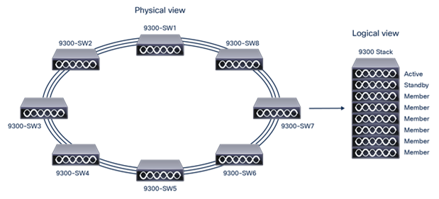
Simplified Cisco Catalyst 9300 Series physical and logical views
Stacking cables are mandatory for stacking architecture. Stacking cables that support Cisco Catalyst 3850 Series Switches can be used for the 9300 modular uplink models, making them backward compatible. Depending on the physical setup of the infrastructure, different lengths of stacking cable may be needed. Each Cisco Catalyst switch supports a maximum of two stack cables for data stacking Table 1 and 2 list the available stacking cables for Catalyst 9300 models.
Table 1. Different orderable stack cables for Modular Uplink models
| Product ID |
Description |
| STACK-T1-50CM |
50CM Type 3 Stacking Cable |
| STACK-T1-1M |
1M Type 3 Stacking Cable 3M |
| STACK-T1-3M |
Type 3 Stacking Cable |
For 9300 fixed uplink models, stack kit is mandatory for StackWise-320 and has to be ordered separately. Each stack kit consists of two stack adapters and one data stack cable.
Table 2. Different orderable stack cables for 9300L fixed uplink models
| Product ID |
Description |
| STACK-T3-50CM |
50CM Type 3 Stacking Cable (Default cable with 9300L Stack kit) |
| STACK-T3-1M |
1M Type 3 Stacking Cable |
| STACK-T3-3M |
3M Type 3 Stacking Cable |
Table 3. Different orderable stack cables for 9300LM fixed uplink models
| Product ID |
Description |
| STACK-T3A-50CM |
Data stack 50cm cable (default cable with C9300LM Stack Kit) |
| STACK-T3A-1M |
Data stack 1m cable (cable option with C9300LM Stack Kit) |
| STACK-T3A-3M |
Data stack 3m cable (cable option with C9300LM Stack Kit) |
Stack ports
Each Cisco Catalyst 9300 switch with modular uplinks comes with two stack ports located on the back panel of the switch to support the StackWise-1T/480 architecture. Figure 3 shows the stack port location on the 9300 Series switches.

Stack cable and stack cable slot for 9300 modular uplink models (C9300 and C9300X)
For Cisco Catalyst 9300 switches with fixed uplink modules, stack kit has to be ordered which contains two stack adapters and one stack cable.

Stack adapter for the 9300 fixed uplink models.
Stack connectors
Figure 5 shows the stack connector for the Catalyst 9300 switch with modular uplinks. All stack ports are identical on all Cisco Catalyst 9300 Series modular uplink models. Any side of the stack cable can connect to any stack port. Make sure the screws are completely tightened and the connection is secure.

Stack connector for 9300 modular uplink models(C9300 and C9300X)
Figure 6 shows the stack connector for the Catalyst 9300 switch with fixed uplinks. All stack ports are identical on all Cisco Catalyst 9300 Series fixed uplink models. Any side of the stack cable can connect to any stack port. Make sure the screws are completely tightened and the connection is secure.

Stack connector for 9300 fixed uplink models
Ring architecture
When the stack is operating in a full ring, it can deliver high-speed performance throughput of 1T/480/320 by each stack-member switch. This multifold performance improvement is possible by combining the new internal UADP ASIC and dual stack ports.
The high-speed backplane of the Cisco Catalyst 9300 Series stack-ring fabric is constructed by daisy-chaining the stack-member switches with Cisco proprietary cables that connect rear-side stack ports. The Cisco stack fabric consists of six unidirectional data transmission rings.
Figure 7, 8 and 9 provides a graphical illustration of the 9300 Series StackWise-1T/480/320 internal forwarding architecture.
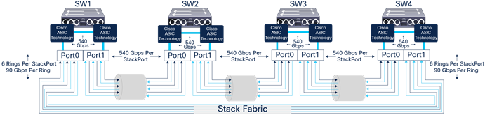
Cisco Catalyst 9300X StackWise-1T internal forwarding architecture (Modular Uplink Models)
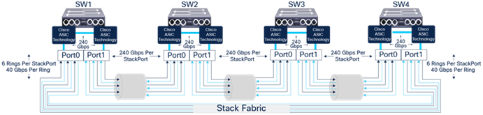
Cisco Catalyst 9300 StackWise-480 internal forwarding architecture (Modular Uplink Models)
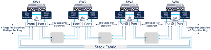
Cisco 9300L/9300LM Stackwise-320 internal forwarding architecture (Fixed Uplink Models)
The aggregated throughput that a stack of switches supports is a combination of two major factors:
Total transmission rings: Each stack connector bundles multiple individual cables that carry data across the stack ring. The cabling structure creates six/four internal stack rings for modular/fixed uplink models, respectively. This hardware design significantly improves the data transmission performance of each stack port of a Cisco Catalyst 9300 Series Switch.
Maximum throughput per ring: Each stack ring can transmit data up to 80 Gbps for Catalyst 9300X series and 40G for Catalyst 9300/9300L/C9300LM. For Catalyst 9300X models, we have six internal stack rings which will enable an aggregated throughput of 540G per switch (up to 1000G of unicast with Spatial Reuse Protocol [SRP]) and similarly Catalyst 9300 Modular Uplink models have six internal stack rings which enable aggregated throughput of 240G per switch (up to 480G of unicast with Spatial Reuse Protocol [SRP]). For fixed uplink module models, we have 4 internal stack rings to enable an aggregated throughput of 160G per switch (up to 320G of unicast with Spatial Reuse Protocol [SRP]).
Table 4 describes the major details of the stacking architecture.
Table 4. Cisco StackWise architecture details
|
|
Catalyst 9300X (Stackwise-1T) |
Catalyst 9300 modular uplink models (Stackwise-480) |
Catalyst 9300 fixed uplink models (Stackwise-320) |
| Total number of rings |
6 |
6 |
4 |
| Throughput per ring |
90 Gbps |
40 Gbps |
40 Gbps |
| Throughput per stack (full ring) |
540 Gbps |
240 Gbps |
160 Gbps |
| Throughput per stack (full ring) with SRP |
1 Tbps |
480 Gbps |
320 Gbps |
Stack discovery
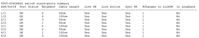
Once all switches are powered on and the stack interfaces are up, the Stack Discovery Protocol (SDP) discovers the stack topology using broadcasts. Neighbor information is shared with all other switches in the stack. In a full ring, discovery exits after all the members are found. In a half ring, the system waits for two minutes. Once all switches are discovered, switch numbers are determined. After switch number conflicts are resolved, the information is stored in a flash variable block for future use. ACTIVE election begins after discovery exits.
The following command can be used to check the status of the stack cable and to identify the neighbor device of the stack cable.
Active election
To determine the single ACTIVE and STANDBY switch role during the complete stack reboot process or during the initial boot-up, all switches are required to go through an election process. All member switches participate in the election of an ACTIVE stack switch if they all boot up within the election window (120 seconds).
The following parameters are taken into account in the order listed below for active switch election:
● Highest priority
● Lowest MAC address
STANDBY is elected by the ACTIVE switch after two minutes to reduce the stress of high-availability sync on the stack.
By default, the priority is 1 for all switches; hence it falls back to the MAC address to determine the ACTIVE switch if a priority is not defined explicitly. The switch with a lower MAC address will take the role of the ACTIVE switch. The remaining switches join the stack as member switches. Once all the switches in the stack are discovered as members, the ACTIVE switch elects the STANDBY switch. Any switch that you add to the stack after the completion of election process is considered a straggler and will not participate in the ACTIVE stack switch election.
For deterministic system role election, it is recommended to adjust the switch priority for all stack switches. The switch with a higher priority becomes the ACTIVE switch. This configuration is a one-step process and is typically done at the time of the initial switch boot-up. The switch priorities are set in the ROMMON configuration of each individual switch in the stack ring. The switch priority configuration from ROMMON is parsed during the boot cycle instead of reading from the startup configuration stored in NVRAM.
Thus, the switch-priority configuration cannot be verified from startup or the running configuration since it is programmed into a different configuration component.
The priority of the Cisco Catalyst 9300 Series Switch can be modified from the EXEC mode. A reload is required for the change to take effect. The following commands show how to configure the switch priority and change switch numbers.
| Cisco Catalyst 9300 Series |
| 9300>enable 9300#switch <number> priority 15 !Set priority 15 to elect switch in ACTIVE role 9300#switch <number> priority 14 !Set priority 14 to elect switch in STANDBY role 9300#switch <number> priority 13 !Set priority 13 to elect switch in next STANDBY role 9300#switch <number> priority 12 !Set priority 12 to elect switch in next STANDBY role 9300>enable 9300#switch <number> renumber <number> !Statically renumber switch in stack-ring |
There are two ways to influence a particular switch in the stack to take over the role of an ACTIVE switch:
● Configure the switch with the highest priority [highest priority is 15] to assume the role of the ACTIVE switch.
● If you prefer a particular switch to be the ACTIVE switch in the stack, power on that switch first to take on the role of the ACTIVE switch.
Some conditions apply for switches when deployed in StackWise-1T/480/320
● Valid switch numbers are 1 through 8 for Cisco Catalyst 9300 Series Switches. The port numbers of the member switches begin with the switch number, such as Gig1/0/1, Te1/1/1, or Fo1/1/1, depending on whether the ports are Gigabit Ethernet (GE), 10 GE, or 40 GE. Example: Switch 3 would have G3/0/1, Te3/1/1, Fo3/1/1
● Switch numbers are persistent, meaning that each switch keeps the same switch number after it reboots as a stack member, even if it is no longer part of the stack.
● The stack ACTIVE switch resolves any switch number conflicts and renumbers the switch.
● Switch numbering does not reflect the physical location of the switch. However, the numbering can be changed to match the physical location using the command “switch current-stack-member-number renumber new-stack-member-number” from the enable mode.
Example: “switch 1 renumber 2” renames switch 1 to 2 and changes the port numbers from G1/1/1 and Te1/1/1 to G2/1/1 and Te2/1/1. A reload is required for this to take effect.
When you disconnect a stack member, the switch numbers and port numbers of the remaining stack members do not change, and the stack does not reload.
The system roles in the resilient StackWise-1T/480/320 architecture can be verified by running the commands shown below.
9300-STACK#show switch
Switch/Stack Mac Address: 046c.9d1f.3400 - Local Mac Address
Mac persistency wait time: Indefinite
H/W Current
Switch# Role Mac Address Priority Version State
---------------------------------------------------------------
*1 Active 046c.9d1f.3400 15 V01 Ready
2 Standby 046c.9d1f.3b80 14 V01 Ready
3 Member 046c.9d1f.6c00 13 V01 Ready
4 Member 7001.b544.5700 12 V01 Ready
9300-STACK#show redundancy
Redundant System Information :
------------------------------
Available system uptime = 2 days, 20 minutes
Switchovers system experienced = 0
Standby failures = 0
Last switchover reason = none
Hardware Mode = Duplex
Configured Redundancy Mode = sso
Operating Redundancy Mode = sso
Maintenance Mode = Disabled
Communications = Up
Current Processor Information :
-------------------------------
Active Location = slot 1
Current Software state = ACTIVE
Uptime in current state = 2 days, 20 minutes
Image Version = Cisco IOS Software [Fuji], Catalyst L3 Switch Software (CAT9K_IOSXE), Version 16.9.1, RELEASE SOFTWARE (fc2)
Technical Support: http://www.cisco.com/techsupport
Copyright (c) 1986-2018 by Cisco Systems, Inc.
Compiled Tue 17-Jul-18 17:00 by mcpre
BOOT = flash:packages.conf
CONFIG_FILE =
Configuration register = 0x102
Peer Processor Information :
----------------------------
Standby Location = slot 2
Current Software state = STANDBY HOT
Uptime in current state = 2 days, 16 minutes
Image Version = Cisco IOS Software [Fuji], Catalyst L3 Switch Software (CAT9K_IOSXE), Version 16.9.1, RELEASE SOFTWARE (fc2)
Technical Support: http://www.cisco.com/techsupport
Copyright (c) 1986-2018 by Cisco Systems, Inc.
Compiled Tue 17-Jul-18 17:00 by mcpre
BOOT = flash:packages.conf
CONFIG_FILE =
Configuration register = 0x102
The STANDBY switch, which is in HOT-STANDBY mode, will transition into the ACTIVE role upon detecting failure of the primary ACTIVE switch. A new STANDBY switch will be elected from the available member switches, and it will transition to HOT-STANDBY.
Figure 10 shows the roles and operation of switches in a StackWise-1T/480/320 architecture.
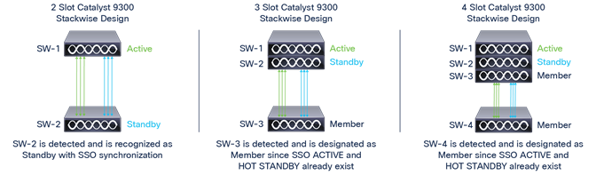
Roles and operation of StackWise-1T/480/320
Stackwise-1T/480/320 architecture
The forwarding architecture in the Cisco Catalyst 9300 Series Switches has been designed to provide 1T/480G/320 of stack bandwidth. The software architecture uses the credit-based token algorithm. To optimally forward the traffic within the stack ring, the packet-stripping function is performed on the destination switch instead of on the source or ingress switch. This mechanism is known as the spatial-reuse forwarding mechanism.
It allows multiple flows to coexist to enable a parallel forwarding design. The spatial-reuse capability significantly boosts data-plane switching performance in the stack-ring switching architecture. The broadcast and multicast packets are still required to do source stripping, since the location of the destination device is known and there could be multiple multicast listener devices within stack ring.
Distributed forwarding architecture
The forwarding architecture is designed to provide distributed switching across all member switches in the stack, as implemented in distributed, modular Cisco platforms. To optimize data-plane performance by using hardware resources from each Cisco Catalyst 9300 Series stack member switch, network services such as QoS, security ACLs, and others are fully distributed and programmed to locally enforce on network ports. This distributed hardware resource utilization process delivers wire-speed switching performance that increases overall system resource capacity, prevents centralized overload processing on the ACTIVE switch, and optimizes stack-ring bandwidth capacity.
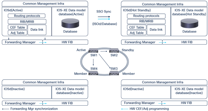
Since Cisco StackWise-1T/480/320 technology is designed to offer modular-class system redundancy in stack design, It requires centralized control and a management plane with a distributed forwarding architecture. To logically appear as a single virtual switch, the IOS daemon (IOSd) process on the ACTIVE switch centrally manages all management-plane and network-control-plane operations with Layer 2 and Layer 3 protocols, including Spanning Tree Protocol (STP), IP routing, Cisco Express Forwarding, Policy-Based Routing (PBR), and others.
Depending on the implemented network protocols, the ACTIVE switch communicates with the rest of the multilayer or routed access infrastructure to dynamically develop the forwarding tables. The ACTIVE switch also updates all member switches for forwarding information. The distributed forwarding capability provides local switching lookup for the switching decision process. All ingress and egress wired data-plane traffic is fully distributed in a StackWise-1T/480/320 based system design.
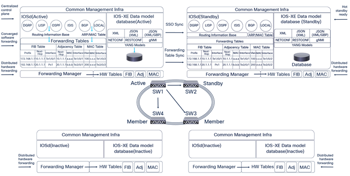
Independent of the IOSd operational state, the hardware Forwarding Information Base (FIB) is actively programmed in ASICs across all stack-member switches in a stack ring. Figure 11 shows the Cisco Catalyst 9300 Series system architecture with centralized processing for control and management functions and distributed forwarding.
Cisco Catalyst 9300 Series and centralized processing
SSO/NSF architecture
The highly resilient Nonstop Forwarding and Stateful Switchover (NSF/SSO) technology is a widely deployed solution in mission-critical campus and branch network designs. The key advantage of NSF/SSO is that it constantly delivers network availability without compromising performance and scalability during planned or unplanned network outages. The StackWise-1T/480/320 architecture takes advantage of the same technology to maintain state machines and gracefully recover during an ACTIVE switch failure.
StackWise-1T/480/320 SSO technology expands Route Processor Redundancy (RPR) capabilities to provide transparent failover of several high-availability-aware Layer 2 and 3 protocols and Cisco IOS Software applications when the ACTIVE switchover occurs.
The state machines of non-high-availability-aware protocols and applications are not synchronized from ACTIVE to STANDBY, something the Cisco Catalyst 9300 Series Switch requires to rebuild adjacencies and forwarding entries during an ACTIVE switch failure.
NSF is a high-availability feature that can ensure continuous Layer 2 and 3 packet forwarding, which continues when an ACTIVE route processor switches over to a STANDBY switch. It effectively increases network availability by eliminating network downtime in the event of scheduled maintenance or an unexpected failure of the switch. NSF is used in conjunction with SSO. NSF enhances the Cisco Express Forwarding logic to allow Cisco Catalyst 9300 Series Switches in StackWise-1T/480/320 to continue using their last known forwarding information base data when a newly elected ACTIVE switch is learning routes.
Figure 12 shows the NSF/SSO architecture in Cisco Catalyst 9300 Series StackWise-1T/480/320 mode.
Cisco Catalyst 9300 Series StackWise-1T/480/320 NSF/SSO architecture
Implementing StackWise-1T/480/320 NSF/SSO
To increase availability, the SSO capability is enabled by default when Cisco Catalyst 9300 Series Switches are deployed in StackWise-480/320 mode. No additional user intervention is required to enable the SSO capability on a Cisco Catalyst 9300 Series system. The user can verify that SSO is configured and that the operational state is using a consistent CLI as a modular Cisco Catalyst system. The following example shows the sample output of SSO redundancy in the StackWise-1T/480/320 based network design.
9300-STACK#sh redundancy states
my state = 13 -ACTIVE
peer state = 8 -STANDBY HOT
Mode = Duplex
Unit = Primary
Unit ID = 1
Redundancy Mode (Operational) = sso
Redundancy Mode (Configured) = sso
Redundancy State = sso
Maintenance Mode = Disabled
Manual Swact = enabled
Communications = Up
client count = 109
client_notification_TMR = 30000 milliseconds
RF debug mask = 0x0
The NSF capability on Cisco Catalyst 9300 Series Switches can perform as an NSF helper system. However, with SSO protocol synchronization, the Cisco Catalyst 9300 Series system becomes an NSF-capable system as a modular Cisco Catalyst system. To enable the graceful restart capability for supported protocols, the network administrator must manually enable the graceful restart capability under a routing instance; otherwise the system may not gracefully recover protocol state machines and may cause a high recovery time during an ACTIVE switch failure event. The following code shows an example of how to enable NSF for the Enhanced Interior Gateway Routing Protocol (EIGRP).
9300-STACK(config)#router eigrp 100
9300-STACK(config-router)#nsf
9300-STACK#sh ip protocols
*** IP Routing is NSF aware ***
Routing Protocol is “eigrp 100”
<SNIP>
NSF-aware route hold timer is 240
EIGRP NSF enabled
NSF signal timer is 20s
NSF converge timer is 120s
Router-ID: 172.168.2.2
Switch addition
When adding a new switch to the stack, stack cables have to be connected appropriately prior to powering on the switch. The stack will operate at half bandwidth until the newly added switch has been powered on and has been discovered as a member. Once the switch had been discovered and is part of the stack, the stack ring transitions to the “Full” state.
The following output shows that the stack is in “Half” ring state until the newly added switch is discovered.
9300-STACK#show switch stack-ring speed
Stack Ring Speed : 240G
Stack Ring Configuration : Half
Stack Ring Protocol : StackWise
Figure 13 shows the stack cabling when three switches are operating in StackWise-1T/480/320.

Stack with three switches
Figure 14 shows the stacking cable structure when a fourth switch has been added to the above stack.

StackWise-1T/480/320 with four switches
The following logs describe the addition of a new switch to the stack.
| Newly added member switch logs |
| Initializing Hardware... <SNIP>
Current ROMMON image: Primary Last reset cause : PowerOn C9300-24UX platform with 8388608 Kbytes of main memory boot: attempting to boot from [flash:packages.conf] boot: reading file packages.conf < SNIP > Waiting for 120 seconds for other switches to boot
The switch number is 4 All switches in the stack have been discovered. Accelerating discovery |
| The stack discovers this new switch and assigns a switch number of 4, as seen below: |
| 9300-STACK#
*Aug 20 18:44:51.427: %STACKMGR-6-SWITCH_ADDED: Switch 2 R0/0: stack_mgr: Switch 4 has been added to the stack. *Aug 20 18:44:51.428: %STACKMGR-6-SWITCH_ADDED: Switch 1 R0/0: stack_mgr: Switch 4 has been added to the stack. *Aug 20 18:44:51.430: %STACKMGR-6-SWITCH_ADDED: Switch 3 R0/0: stack_mgr: Switch 4 has been added to the stack.
<SNIP> *Aug 20 18:44:57.034: %STACKMGR-6-SWITCH_ADDED: Switch 4 R0/0: stack_mgr: Switch 4 has been added to the stack. *Aug 20 18:44:57.034: %STACKMGR-6-SWITCH_ADDED: Switch 4 R0/0: stack_mgr: Switch 4 has been added to the stack. *Aug 20 18:44:57.249: %HMANRP-6-HMAN_IOS_CHANNEL_INFO: HMAN-IOS channel event for switch 4: EMP_RELAY: Channel UP! |
It is recommended to have the stack cables connected to the newly added switch prior to powering it on. If the stack cables are connected after the switch has been powered on, it will result in reload of the newly added switch. A similar message will be seen during this process on the new switch, resulting in a reload:
“Chassis 1 reloading, reason - stack merge”
Switch deletion
To remove a switch from the stack, the respective switch has be powered down and the stack cables have to be disconnected from the switch. The stack will operate at half bandwidth during this state until the stack cables are reconnected to form a full ring.
Figures 15 and 16 show stack cable connections before and after the removal of SW-4 from the stack.

Stack cable connections with four switches in the stack
SW-4 has been removed and the stack cable connections have been moved to bring the ring to the “Full” state.

Stack cable connections after switch 4 has been removed from the stack
Stack split
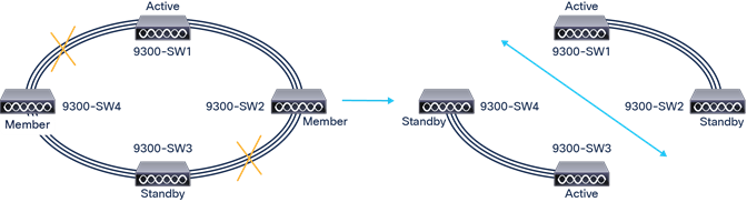
Figure 17 shows a common stack split scenario.
Stack split scenario
When a stack split happens for unforeseen reasons, the member switches reload as they lose connectivity to both the ACTIVE and STANDBY switches, as shown in Figure 17.
Chassis 3 reloading, reason - lost both active and standby Chassis
4 reloading, reason - lost both active and standby
SW-3 and SW-4 discover each other during the reload process and the ACTIVE switch is elected. The ACTIVE switch elects the STANDBY switch. In this scenario, the stack ring will continue to operate at half bandwidth until the link has been restored.
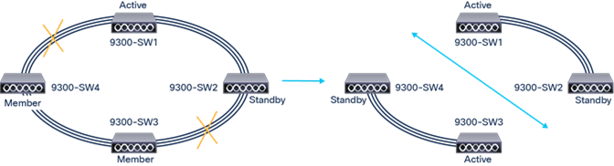
Figure 18 illustrates another stack-split scenario.
Another stack split scenario
The scenario in Figure 18 shows a stack split with the ACTIVE and STANDBY switches being split. In this scenario, none of the switches reload, as both the right half and left half have either an ACTIVE or STANDBY switch. In the right half topology, a new standby switch is elected. In the left half topology, the STANDBY switch takes over the ACTIVE role and a new STANDBY switch is elected. Both topologies operate at half bandwidth until the stack link restores.
Stack merge
When a stack merge occurs, as shown in Figure 20, the stack pair that has the lowest priority on the ACTIVE switch will reload and join the stack pair that has the highest priority. If the priority is same, the ACTIVE switch in the stack pair with the highest MAC address reloads.
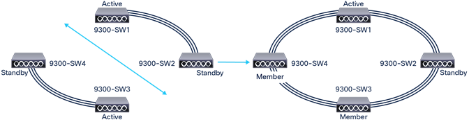
Stack merge scenario
In Figure 20, considering that SW-1 has a priority of 15, SW-2 has a priority of 14, SW-3 has a priority of 13, and SW-4 has a priority of 12, the stack merge will result in a reload of all switches only in the left half of the stack (SW3 and SW4), as they have a lower priority. The stack operates at “Half” ring until the switches in the left half have been discovered as members. If the priority is the same for all switches, the stack with the highest MAC address will reload.
Auto-upgrade
One of the options that gives the StackWise-1T/480/320 architecture greater flexibility is the ability to increase the number of ports in the wiring closet without needing to configure the management plane or upgrade the newly installed switch manually. The newly added switch automatically upgrades to the software that the stack is currently running, without any manual intervention. The hardware and software architecture of the Cisco Catalyst 9300 Series continues to provide backward compatibility to dynamically insert a new 9300 Series switch into the stack ring without a major network disruption. The system and management operation, network configuration, and topologies remain transparent for network upgrades and nonstop business communication.
As a best practice, the newly joined switch can automatically receive consistent software versions from an ACTIVE switch and bring the system online without any user intervention. To automatically download consistent software versions to newly joined switches, you can use the following command from the global configuration mode. The auto-upgrade feature is not supported in bundled mode.
9300-STACK#conf t
Enter configuration commands, one per line. End with CNTL/Z.
9300-STACK(config)#software auto-upgrade enable
With the aforementioned command enabled, any member switch that is added to the stack will automatically upgrade to the current stack software.
| Stack logs |
| 9300-STACK# *Aug 20 22:56:20.696: %STACKMGR-6-SWITCH_ADDED: Switch 2 R0/0: stack_mgr: Switch 4 has been added to the stack. *Aug 20 22:56:20.697: %STACKMGR-6-SWITCH_ADDED: Switch 1 R0/0: stack_mgr: Switch 4 has been added to the stack. *Aug 20 22:56:20.740: %STACKMGR-6-SWITCH_ADDED: Switch 3 R0/0: stack_mgr: Switch 4 has been added to the stack. *Aug 20 22:56:21.172: %BOOT-3-BOOTTIME_INCOMPATIBLE_SW_DETECTED: Switch 1 R0/0: issu_ stack: Incompatible software detected. Details: Chassis 4 is detected INCOMPATIBLE with software version of Active: FAILED: Version ‘16.06.03’ mismatch with Active’s running version ‘16.09.01’ for package: ‘guestshell’ *Aug 20 22:56:21.298: %AUTO_UPGRADE-5-AUTO_UPGRADE_START_CHECK: Switch 1 R0/0: auto_ upgrade_client: Auto upgrade start checking for incompatible switches. *Aug 20 22:56:24.452: %IOSXE_INFRA-6-PROCPATH_CLIENT_HOG: IOS shim client ‘chasfs’ has taken 3168 msec (runtime: 0 msec) to process a ‘stack chasfs fd’ message. *Aug 20 22:56:25.476: %AUTO_UPGRADE-5-AUTO_UPGRADE_INITIATED: Switch 1 R0/0: auto_ upgrade_client: Auto upgrade initiated for switch 4. *Aug 20 22:56:25.502: %AUTO_UPGRADE-5-AUTO_UPGRADE_SEARCH: Switch 1 R0/0: auto_upgrade_ client: Searching stack for software to upgrade switch 4. *Aug 20 22:56:25.518: %AUTO_UPGRADE-5-AUTO_UPGRADE_FOUND: Switch 1 R0/0: auto_upgrade_ client: Found donor switch 1 to auto upgrade switch 4. *Aug 20 22:56:25.534: %AUTO_UPGRADE-5-AUTO_UPGRADE_START: Switch 1 R0/0: auto_upgrade_ client: Upgrading switch 4 with software from switch 1. *Aug 20 22:57:05.536: %AUTO_UPGRADE_MODULAR-5-SMU_AUTO_UPGRADE_INITIATING: Switch 1 R0/0: auto_upgrade_client: Initiating SMU autoupgrade for switch 4 *Aug 20 22:57:05.904: %AUTO_UPGRADE-5-AUTO_UPGRADE_FINISH: Switch 1 R0/0: auto_upgrade_ client: Finished installing software on switch 4. à upgrade complete *Aug 20 22:57:09.625: %AUTO_UPGRADE-5-AUTO_UPGRADE_RELOAD: Switch 1 R0/0: auto_upgrade_ client: Reloading switch 4 to complete the auto upgrade. à reload after upgrade
<SNIP >
*Aug 20 23:00:07.066: %STACKMGR-6-SWITCH_ADDED: Switch 4 R0/0: stack_mgr: Switch 4 has been added to the stack. |
Cisco StackWise technology supports mixed stacking between the Catalyst 9300X and Catalyst 9300 Sku’s to achieve lower costs and simplified network design for Enterprise Campuses and branch network design. The Catalyst 9300X FIbre and copper SKu’s can be stacked together using StackWise 1T to achieve an aggregated throughput of 1000 Gbps. As well as the Cisco Catalyst 9300X fibre/Copper SKu’s can also be stacked together with Cisco 9300 Modular uplink sku’s to achieve aggregated stacking bandwidth of 480 Gbps.
Default Operation
The default back stack interface speed is 480 Gbps for Cisco Catalyst 9300 and 9300X switches.
● If the stack group consist of homogeneous Catalyst 9300X connected in full ring architecture with less than 15 minutes of uptime the stack reloads automatically and achieve aggregated throughput of 1 Tbps.
● If the stack group consist of homogeneous Catalyst 9300X connected in half ring or with uptime more than 15 minutes then the automatic reload to higher throughput doesn’t happen and the switch needs to be manually configured via the CLI to achieve 1Tbps throughput.
| CLI Command to change Stack throughput |
| C9300X(config)#switch stack-speed high WARNING: Please confirm all switches physically connected to the stack are in Ready state with 'show switch' CLI command. Otherwise, some switches may not be able to join the stack after the reload, due to speed mismatch. Stack bandwidth setting can be verified using 'show switch stack-bandwidth' command. It will require a reboot for the new stack speed to take effect. Do you want to continue?[y/n]? [yes]: y |
● If the stack group consist of mix of Catalyst 9300 and Catalyst 9300X in full ring, for the first time all the stack members will go for reload and form a stack capable of 480 Gbps throughput. One additional reload is expected at this time to ensure the SDM template for all the members are same (The Feature scale for mixed stacking between C9300X and C9300 will be limited to C9300 Scale). The same behavior is observed for half-ring Stack design.
Adding a Switch to Mix Stack
When adding a new switch to the stack, stack cables must be connected appropriately prior to powering on the switch.
● If a Catalyst 9300X is being added to an existing Catalyst 9300 stack, the member Catalyst 9300X will go for an additional reload before joining the stack in order to match Catalyst 9300 SDM template.
● If a Catalyst 9300 is being added to an existing Catalyst 9300X stack, the member Catalyst 9300 will stay in platform mismatch mode until the complete stack reload is performed.
| Stack Logs |
| 9300-STACK# *Apr 19 22:56:20.696: %STACKMGR-SWITCH: Switch 4: stack_mgr: sdm template mismatch loading lower scale template for mixed stacking.
The Log is observed on adding catalyst 9300X to Mixed stack. The switch undergoes reload to match/load the current SDM template for Stack group. |
Removing a Switch from Mix Stack
To remove a switch from the stack, the respective switch has be powered down and the stack cables have to be disconnected from the switch.
● In full ring Stack design, when Catalyst 9300 is removed from mixed stack and rest of the stack is homogeneous Catalyst 9300X an additional reload is required to bring the stack to Catalyst 9300X SDM template.
● In half ring Stack design, when Catalyst 9300 is removed from mixed stack and rest of the stack is homogeneous Catalyst 9300X, Stack remains in Catalyst 9300 SDM. We don’t upgrade the SDM to C9300X even after stack reload unless a full ring stack design is achieved.
| Stack Logs |
| 9300-STACK# *Apr 19 23:12:15.232: %STACKMGR-SWITCH: Switch 4: stack_mgr: sdm template mismatch loading higher scale template.
The log may be observed when Catalyst 9300 is removed from the Mixed stack to form Catalyst 9300X homogeneous Stack(Full ring). |
Stackwise Mode button behaviour (Stackwise 1T and Stackwise 480)
● Mode button can be used to change individual Switch Stack throughput. The Active switch in Stack can be identified from Active Switch LED. Pressing the button for 10+ seconds can toggle the throughput between 1Tbps or 480Gpbs. (After auto-reload the switch/stack boots up with alternate Stacking throughput 480Gpbs—1Tbps or 1Tbps---480Gbps).
| Stackwise Blue beacon LED behaviour (First 135 second upon Stack intiation) |
| Blue Beacon LED Solid indicates high speed (Stackwise-1T) Blue Beacon LED 1 second-interval blinking indicates low speed (Stackwise-480) |
Licensing with Release 16.9 (Smart Licensing)
With Release 16.9.1, for which a Smart License is mandatory, the stack automatically enables the EVAL license on a new switch should a license mismatch be present on the newly added switch. Data programming will be done once the switch joins the stack.
This can be verified using the following command.
9300-STACK#sh license usage
License Authorization:
Status: AUTHORIZED on Sep 25 22:53:33 2018 UTC
C9300 Network Advantage (C9300-24 Network Advantage):
Description: C9300-24P Network Advantage
Count: 4 à Number of switches in stack
Version: 1.0
Status: AUTHORIZED
C9300 Cisco DNA Advantage (C9300-24 Cisco DNA Advantage):
Description: C9300-24P Cisco DNA Advantage
Count: 4
Version: 1.0
Status: AUTHORIZED
Licensing prior to Release 16.9
Prior to Release 16.9.1, any newly added switch must have the same license as the stack to join the stack. If the newly installed switch does not have same license as the stack, the switch will be discovered but will not join the stack and will be reported as a license mismatch. No data programming will be done for this switch until the compatibility check is passed.
The following message will appear when a switch experiences a license mismatch:
| Logs on the newly added switch with license mismatch |
| “Switch 4 has a license mismatch with the stack. Only on activating a compatible license will the switch join.” |
| Stack reports the license mismatch |
| c9300-STACK#sh switch Switch/Stack Mac Address : 046c.9d1f.3b80 - Local Mac Address Mac persistency wait time: Indefinite H/W Current Switch# Role Mac Address Priority Version State --------------------------------------------------------------------- *1 Active 046c.9d1f.3b80 15 V01 Ready 2 Standby 046c.9d1f.3400 14 V01 Ready 3 Member 046c.9d1f.6c00 13 V01 Ready 4 Member 7001.b544.5700 12 V01 Lic-Mismatch |
Manual intervention is needed to resolve this issue. This can be corrected by activating a Right-To-Use (RTU) license, followed by reloading the switch.
c9300-1#license right-to-use activate network-advantage slot 4 accept General Terms
c9300-1#license right-to-use activate addon Cisco DNA-advantage evaluation slot 4 accept General Terms
c9300-1#reload slot 4
Simplified multilayer network design
The enterprise customer relies on real-time business applications such as voice, video, and others. The system reliability and network availability become a core, integrated service requirement to deliver nonstop communication in the network.
When the access layer environment becomes highly dense, the StackWise-1T/480/320 pools up to eight physical chassis into a single logical system from a network design perspective. As the access layer network infrastructure expands, the device-pooling capability of the Cisco StackWise technology significantly simplifies operations and the network architecture itself.
Cisco recommends designing and deploying the multilayer distribution block with four major elements in the overall architecture: reduced fault domain, increased network security, deterministic forwarding paths, and optimal resiliency. Designing and developing a wiring closet with this architecture requires isolated broadcast domains or VLANs for each workgroup category, device, and application type. This network design needs to apply consistently throughout the wiring closet network. It provides solid network security, stability, and reliability, and depending on the access layer network size, it may increase operational and troubleshooting complexity due to the increased number of VLANs, subnets, neighbor counts, and more.
The Cisco Catalyst 9300 Series StackWise-1T/480/320 device-pooling design retains Cisco’s multilayer design principles. It also simplifies operational challenges with a reduced number of VLANs, STP instances, subnets, neighbor counts, etc. at the access and distribution layers. Figure 20 shows the simplified network design and operational data points between 9300 Series switches deployed in standalone mode in comparison to StackWise-1T/480/320 mode.
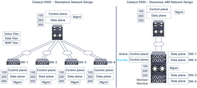
Comparison of Cisco Catalyst 9300 Series Switches in standalone mode to a StackWise-1T/480/320 multilayer
Scalable StackWise-1T/480/320 cross-stack EtherChannel design
StackWise-1T/480/320 can enable the ability to build a single-uplink EtherChannel interface by bundling up to eight parallel physical links, which could then be distributed evenly across all stack switches. Multiple uplinks from a mission-critical access layer switch are a base requirement for reliable networks to provide high-speed data load sharing and to deliver 1+1 path redundancy upon failure.
However, from a forwarding perspective the Layer 2 network becomes suboptimal when multiple parallel interfaces are deployed between two Layer 2 Ethernet switches.
The cross-stack EtherChannel interface simplifies STP topology over the logical interface and builds loop-free forwarding paths across all bundled uplink ports. If the Cisco Catalyst 9300 Series Switch is deployed in routed access mode, the cross-stack EtherChannel can also be deployed as a Layer 3 uplink interface to simplify unicast or multicast neighbor adjacencies and simplified network topology with one forwarding table. Independent of the 9300 Series switch’s deployed mode (multilayer or routed access), during the member switch or member link failure the EtherChannel does not disrupt network topology tables and delivers deterministic, hardware-driven, subsecond network recovery processes.
Cisco Catalyst 9300 Series Switches support multiple physical uplink ports to connect distribution-layer switches. Typically, up to two physical uplink interfaces are deployed from access layer switches for optimal load balancing and redundancy in the wiring closet.
When these switches are deployed in stack configuration mode, we recommend maintaining the same uplink connection design principle as a dual stack-member system. The recommendation is to use uplinks on the member switches with Multichassis EtherChannel (MEC), which helps with spanning multiple uplinks over the member switches. For example, eight Cisco Catalyst 9300 Series Switches deployed in a stack ring would have multiple diversified uplink ports from member switches. The remaining switches, where uplinks are not connected, would forward the data toward the core using a high-speed stack backplane.
This recommended uplink port design offers various benefits, from application performance to optimal user experience. Some key benefits include:
● Improved application performance by increasing aggregated stack switching capacity with multiple, distributed, high-speed 10-Gbps/40-Gbps uplinks between stack member Cisco Catalyst switches
● Enhanced bidirectional traffic engineering with intelligent network data load sharing within the stack ring and across all distributed uplink physical ports
● Improved system and application performance by using the distributed forwarding architecture advantage of hardware resources: buffers, queues, Ternary Content-Addressable Memory (TCAM), and others
● Protection of the stack and network-level redundancy and reduction in congestion between distributed aggregation systems caused during a major outage at the access or distribution layer.
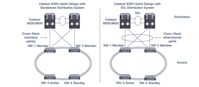
Cisco Catalyst 9300 Series StackWise-1T/480/320 uplink design best practices
Optimal StackWise-1T/480/320 cross-stack forwarding EtherChannel design
The egress data load forwarding from StackWise-1T/480/320 is determined based on how the upstream network is designed. The loop-free forwarding topology uses all available paths to switch data traffic based on precomputed Cisco Express Forwarding or EtherChannel hash results. In a distributed forwarding architecture the Cisco Catalyst 9300 Series stack switches verify the Layer 2 to Layer 3 data variables from incoming traffic to determine the best physical uplink ports before forwarding traffic to the upstream system.
The Cisco Catalyst 9300 Series Switch requires more variables in packet tuples to perform granular switching decisions. In a large-scale design, the source MAC address-based EtherChannel load-sharing mode may deliver adequate results to use all upstream member links. However, in mid- to low-scale networks, the Cisco Catalyst 9300 Series may not have enough variable points to compute the best egress uplink path. In this case, in order to optimize the switching performance with granular packet forwarding decisions across all available cross-stack uplink paths, the default EtherChannel hash computation can be tuned to include Layer 2 to Layer 3 address variables.
The next-generation Cisco Catalyst 9300 Series is designed to support a large number of EtherChannel hash variables to deliver optimal upstream egress forwarding decisions. Table 5 outlines the supported Layer 2 to Layer 4 EtherChannel hash algorithm.
Table 5. Cisco Catalyst 9300 Series EtherChannel hash algorithm
| Layer |
EtherChannel hash |
| Non-IP |
src-mac (default) |
| Layer 2 |
src-mac (default) dst-mac src-dst-mac |
| Layer 3 |
src-ip dst-ip src-dst-ip |
| Layer 4 |
src-port dst-port src-dst-port |
| Layer 3 plus layer 4 |
src-mixed-ip-port dst-mixed-ip-port src-dst-mixed-ip-port (Recommended) |
The network administrator can adjust the default EtherChannel hash algorithm from a global configuration mode, as demonstrated in the sample code that follows.
Verification:
9300-STACK#show etherchannel load-balance
EtherChannel Load-Balancing Configuration:
9300-STACK#conf t
src-mac
9300-STACK(config)#port-channel load-balance src-dst-mixed-ip-port
EtherChannel Load-Balancing Addresses Used Per-Protocol:
Non-IP: Source MAC address
IPv4: Source MAC address
IPv6: Source MAC address
Command to change the default load-balance method:
Verification:
9300-STACK#sh etherchannel load-balance
EtherChannel Load-Balancing Configuration:
src-dst-mixed-ip-port
EtherChannel Load-Balancing Addresses Used Per-Protocol:
Non-IP: Source XOR Destination MAC address
IPv4: Source XOR Destination IP address and TCP/UDP (layer-4) port number
IPv6: Source XOR Destination IP address and TCP/UDP (layer-4) port number
Reliable StackWise-1T/480/320 cross-stack forwarding EtherChannel design
The link aggregation protocols build stateful, consistent, and reliable EtherChannel communication between two systems. To successfully establish a logical EtherChannel interface between two systems, the link aggregation protocol performs several link parameter checks to assure that each member link is equipped to deliver consistent switching performance and network service in the event of failure. During the EtherChannel startup process, each end of the system verifies the capabilities of each local and remote member link, including attributes such as speed, duplex, protocol dependencies, QoS capabilities, and more.
Cisco recommends bundling the cross-stack EtherChannel interface using link aggregation protocols such as Cisco Port Aggregation Protocol Plus (PAgP+) or Link Aggregation Control Protocol (LACP). The Cisco Catalyst 9300 Series Switch deployed in StackWise-1T/480/320 supports both link aggregation protocols (Figure 22).
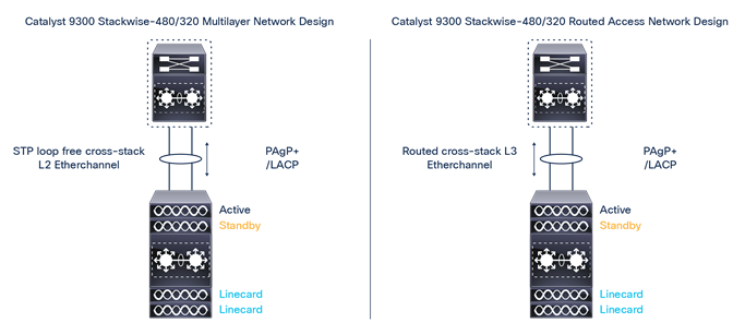
Cisco Catalyst 9300 Series cross-stack EtherChannel design
Next-generation Cisco Catalyst 9300 Series Switches have been designed to meet the future demands in wiring closet networks. Stackwise-1T/480/320 provides maximum port density at the access layer, along with platform, software, and network resiliency at the access layer. As more technologies are integrated into the system, the Cisco Catalyst 9300 Series offers operational simplicity, scalability, performance, and adaptability for future protocols. The software architecture of Cisco StackWise-1T/480/320 technology delivers superior performance and best-in-class resiliency along with the flexibility of a UADP ASIC. This document is primarily focused on the StackWise architecture for the Cisco Catalyst 9300 Series Switches.