Cisco Catalyst 1000 Series Switches White Paper
Available Languages
Bias-Free Language
The documentation set for this product strives to use bias-free language. For the purposes of this documentation set, bias-free is defined as language that does not imply discrimination based on age, disability, gender, racial identity, ethnic identity, sexual orientation, socioeconomic status, and intersectionality. Exceptions may be present in the documentation due to language that is hardcoded in the user interfaces of the product software, language used based on RFP documentation, or language that is used by a referenced third-party product. Learn more about how Cisco is using Inclusive Language.
The network model for small businesses has evolved significantly, from providing basic user connectivity to becoming an overall provider of security, intelligence, and high-speed service. With the significant increase in the number of wired and wireless clients and Internet of Things (IoT) devices, the network should also provide flexibility through ease of management and should power new devices with higher Power over Ethernet (PoE) demands.
Small businesses also require some form of agility, as the requirements change rapidly, either with respect to user connectivity, device onboarding, or connectivity with branch offices.
The Cisco® Catalyst® 1000 Series has been designed and engineered to meet these current requirements and also the future requirements of small businesses.
Introduction to the Cisco Catalyst 1000 Series
The new Cisco Catalyst 1000 Series Switches are fixed Gigabit Ethernet enterprise-class Layer 2 switches designed primarily for small businesses and branch offices. These are simple, flexible, and secure switches ideal for out-of-the-wiring-closet and critical IoT deployments. They are compact and quiet with fanless operation, provide a wide range of port combinations with PoE, and are easy to manage, making them ideal for small businesses and branch office deployments.
The switches operate on Cisco IOS® Software and support flexible device management via both a Command-Line Interface (CLI) and an on-box WebUI. These switches deliver enhanced network security, network reliability, and operational efficiency.
The Cisco Catalyst 1000 Series Switches are fixed, managed Layer 2 switches with quiet, fanless operation (except for a few of the 24- and 48-port SKUs). They are based on a customized merchant Application-Specific Integrated Circuit (ASIC) with an internal ARM CPU architecture. The platform runs the classic Cisco IOS operating system, which enables the switches to support the classic Cisco IOS feature set. The following are some of the highlights of the Cisco Catalyst 1000 Series platform.
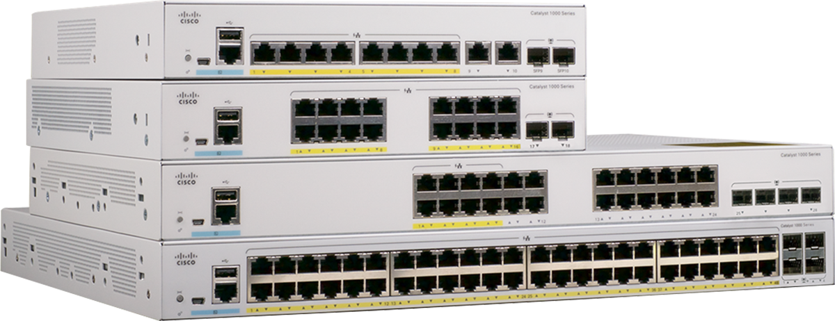
Cisco Catalyst 1000 Series Switches
Downlinks: 8, 16, 24, or 48 Gigabit Ethernet and 24,48 Fast Ethernet data or PoE+ ports with line-rate performance
Fixed uplinks: 2x or 4x Gigabit Ethernet SFP/RJ45 combo uplinks or 4x 10 Gigabit Ethernet Enhanced SFP (SFP+) uplinks
Fixed power supply: Internal power supply, external adapter
PoE: Perpetual PoE+ support with maximum 740W of PoE budget. Multiple PoE port type options are available:
● PoE(P): SKU offering inline PoE power
● Partial PoE(PP): SKU offering PoE on all ports up to the allocated PoE budget
● Full PoE(FP): SKU offering Full PoE across all the ports (15.4W on all ports)
This section briefly covers the high-level system design of the Cisco Catalyst 1000 Series. The architecture offers the option to combine up to eight physical switches as one logical unit using single IP management via the uplink ports.
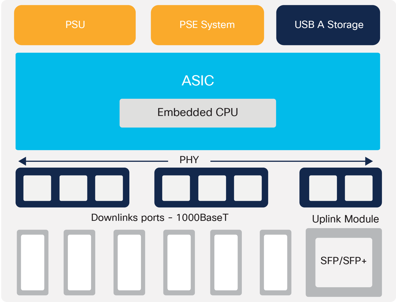
C1000-8/16/24 board layout
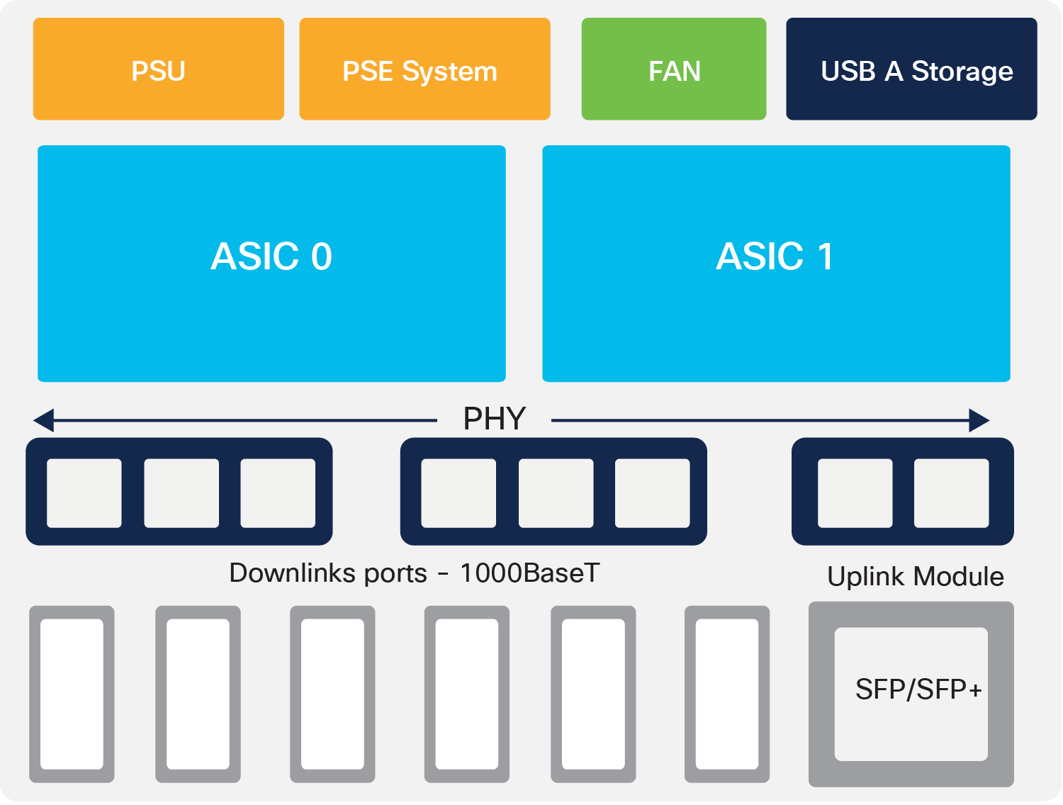
C1000-48 board layout
The Cisco Catalyst 1000 Series Switches come with a single power supply unit built in, with an external power adapter supporting AC power input. The 48-port models and a few of the 24-port models have a built-in fan at the back of the switch. All 1000 Series models come with an RJ45 and USB mini-B port for console access, along with a USB-A port for storage and Bluetooth console access at the front of the switch.
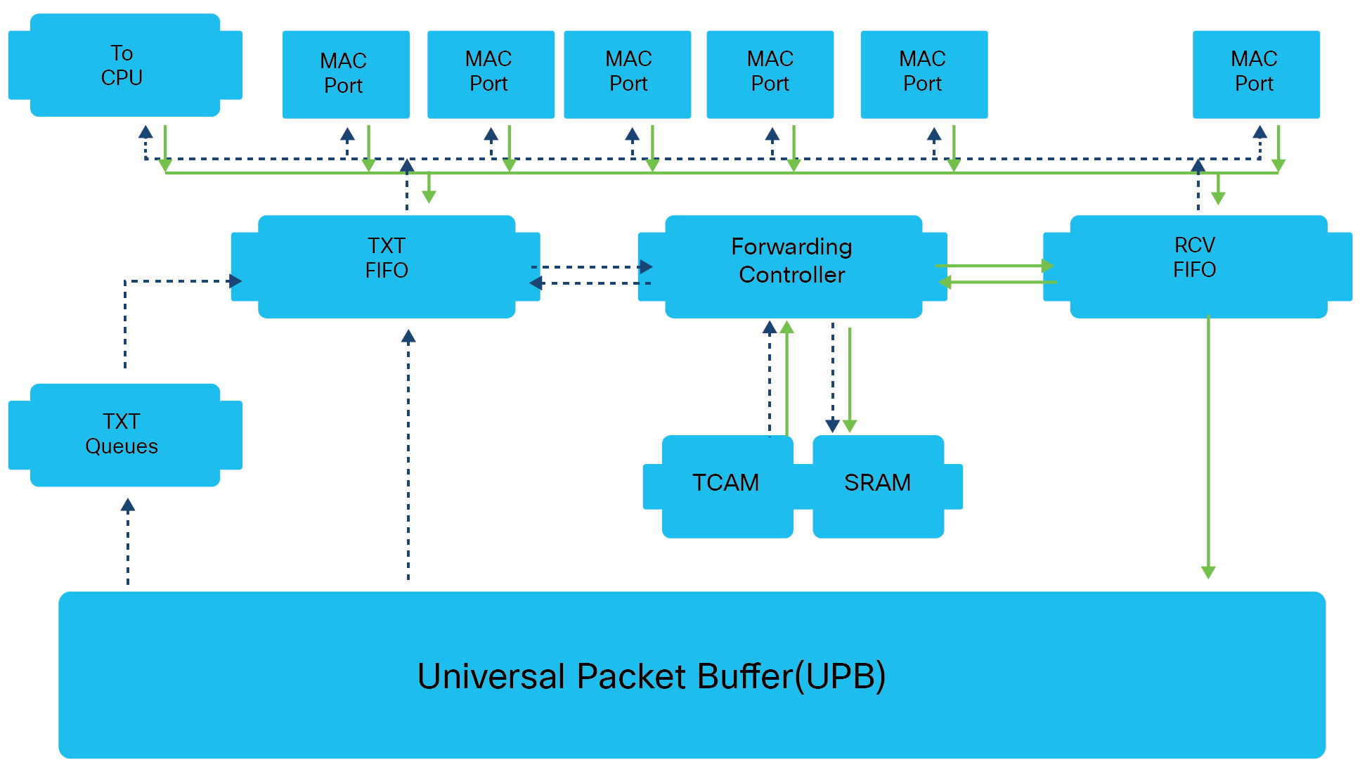
Packet processing
The following is the basic sequence of events when packets enter a Cisco Catalyst 1000 Series Switch.
Ingress path
1) Packets are first received by the Receiver FIFO after VLAN decapsulation.
2) copy of the first packet (initial 200 bytes) is sent into the Forwarding Controller for processing (forwarding, Access Control List [ACL], Quality of Service [QoS] lookups), and another copy of the whole packet is sent to the Universal Packet Buffer (UPB).
3) The Forwarding Controller search engine performs a learning lookup in the Ternary Content Addressable Memory (TCAM) and queries Static RAM (SRAM) for respective information.
4) The Forwarding Controller search engine also performs QoS and ACL lookup in TCAM and queries the SRAM for the respective ingress ACL and QoS response.
5) The Forwarding Controller also performs a lookup for policer and sampled flow (sFlow) to update the result table with an entry pointed to the index.
6) The Forwarding Controller search engine does Layer 2/Layer 3 forwarding lookup in TCAM and an index is returned.
7) The Forwarding Controller sends the index to the SRAM for destination details, and destination information is returned.
8) A descriptor with lookup results is appended to the original packet and stored in the UPB.
Egress path
1) A pointer to the frame is placed on the targeted Transmit Queue.
2) Frame data from the UPB is transferred to the Transmit FIFO.
3) Packets egress out and are stored in the Transmit FIFO for egress processing.
4) The first 200 bytes and descriptor are sent to the Forwarding Controller for egress processing.
5) The Forwarding Controller search engine sends a destination lookup to TCAM and an index is returned.
6) The Forwarding Controller uses the index to get the Layer 2/Layer 3 forwarding information.
7) The Forwarding Controller prepares the packet header and sends it to the Transmit FIFO, where the final packet is assembled.
8) The final packet sent to the Egress Port.
The Cisco Catalyst 1000 Series Switches can be accessed either via a fully managed Cisco IOS CLI or via the WebUI using Cisco Configuration Professional. The switches offer Bluetooth capabilities that enable them to be accessed via Bluetooth for over-the-air access.
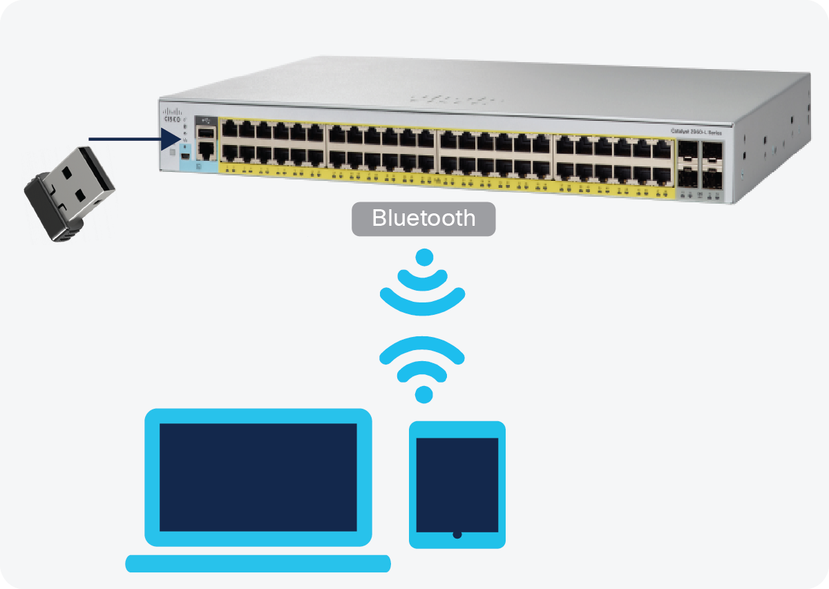
Accessing the switch via Bluetooth
The switches support an external Bluetooth dongle that plugs into the USB port on the switch, allowing a Bluetooth-based RF connection with external laptops and tablets. Laptops and tablets can access the switch CLI using a Telnet or Secure Shell (SSH) client over Bluetooth, whereas the GUI can be accessed over Bluetooth with a browser. The access can be restricted to an Authentication, Authorization, and Accounting (AAA) user or local user configured on the switch.
Provisioning via Cisco Configuration Professional
Cisco Configuration Professional provides a user interface for day-0 provisioning, which enables easy onboarding of the switch. The existing day-0 wizard has been simplified to allow a user to easily set up a wired and wireless network. It hides the underlying complexity associated with provisioning a device with network best practices.
Cisco Configuration Professional provides an intuitive dashboard for configuring, monitoring, and troubleshooting the switch. The dashboard provides a single-pane view of the switch, wherein the user can monitor the connected ports or ports with errors, the health of the switch, the PoE available, and critical alerts on the switch.
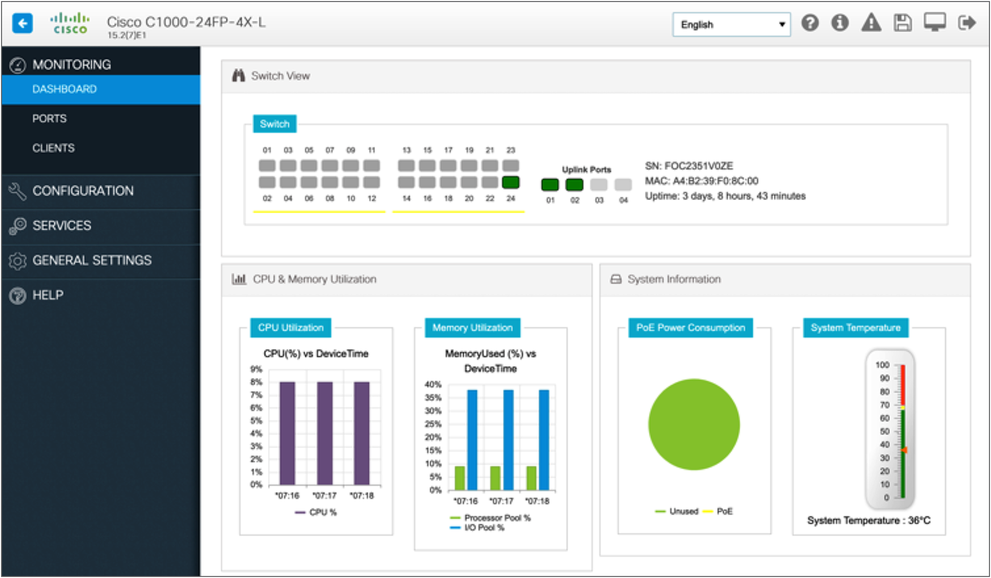
Cisco Configuration Professional dashboard
Single IP management is an efficient feature for managing and monitoring multiple switches as one logical switch using a single IP address. You can use Small Form-Factor Pluggable (SFP) or Enhanced SFP (SFP+) ports with optical cables to connect switches placed at different locations to form a group, where the compact switches are placed in different floors or buildings. The switches can be connected in half-ring or full-ring topologies based on need, and the remaining uplink ports will continue to work as network ports. However, 1G uplink switches can be grouped only with other 1G switches, and 10G uplink switches can be grouped only with 10G switches.
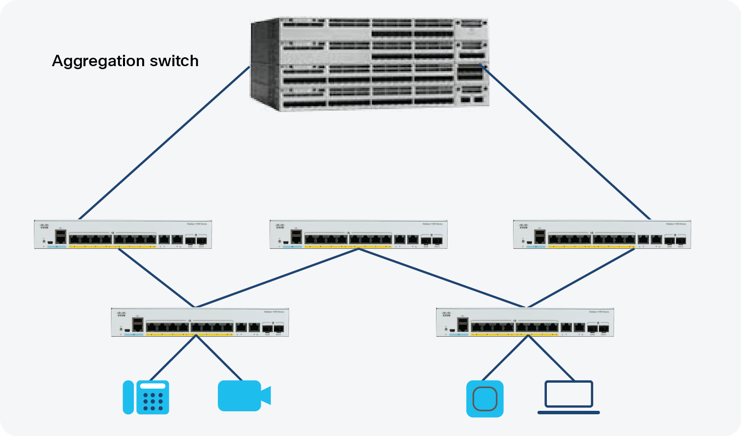
Single IP Management
When you convert a network port to a single IP-managed port, it continues to work as a network port, without any impact to the current running configuration, until the next reload of the device. All current configurations on that particular network port are lost after the reload. When you convert a single IP-managed port back to a network port, it comes up as a network port with the default configuration, after a reload.
Up to eight switches can join a group through single IP-managed ports. A group always has one master, and the other devices act as members. You can have a group with one master and just one member, or as many as seven members. The configuration file for all the switches connected in the group is maintained by the master. The saved and running configuration files for the group are available from the master. All members periodically receive synchronized copies of the configuration files from the master. If the master becomes unavailable, any member that assumes the role of master will have the latest configuration files.
The configuration files record the following settings:
● System-level (global) configuration settings, such as IP, Simple Network Management Protocol (SNMP), Spanning Tree Protocol (STP), and VLAN, that apply to all members.
● Interface-specific configuration settings of all members.
The interface-specific configuration of each member is associated with the member number. Members retain their number unless they are manually changed or the number is used by another member in the same group. If the number changes, the new number takes effect after that member resets.
● If an interface-specific configuration does not exist for that number, the member uses its default interface-specific configuration.
● If an interface-specific configuration exists for that number, the member uses the interface-specific configuration associated with that number.
Once the switches are added to a single IP management group, they can’t be accessed individually, and member configurations and changes are done from the master device. The switches can be accessed via CLI, SNMP, and supported network management applications to manage the group. WebUI can also be used to manage the members.
To convert a network port to a single IP-managed port:
Before reload:
Device# show switch hstack-ports
Horizontal stack port status:
Gi Ports Stack Port Operational Status Next Reload Status Media Type
--------- ------------ -------------------- ------------------- --------------
Gi1/0/9 1 N/W Port Stack Port Fiber
Device(config)#switch 1 hstack-port 1 GigabitEthernet 1/0/9
Device# copy running-config startup-config
Device# reload
After reload:
Device# show switch hstack-ports
Horizontal stack port status:
Gi Ports Stack Port Operational Status Next Reload Status Media Type
--------- ------------ -------------------- ------------------- --------------
Gi1/0/9 1 Stack Port Stack Port Fiber
The following sample output from the “show switch hstack-ports” command shows the status of single IP-managed ports for a 1G group:
Device# show switch hstack-ports
Horizontal stack port status:
Gi Ports Stack Port Operational Status Next Reload Status Media Type
--------- ------------ -------------------- ------------------- -------------
Gi1/0/25 NA N/W Port N/W Port Fiber
Gi1/0/26 1 Stack Port Stack Port Fiber
Gi1/0/27 2 Stack Port Stack Port Fiber
Gi1/0/28 NA N/W Port N/W Port Fiber
Gi2/0/49 1 Stack Port Stack Port Fiber
Gi2/0/50 NA N/W Port N/W Port Fiber
Gi2/0/51 2 Stack Port Stack Port Fiber
Gi2/0/52 NA N/W Port N/W Port Fiber
Gi3/0/49 NA N/W Port N/W Port Fiber
Gi3/0/50 1 Stack Port Stack Port Fiber
Gi3/0/51 NA N/W Port N/W Port Fiber
Gi3/0/52 2 Stack Port Stack Port Fiber
Gi4/0/9 1 Stack Port Stack Port Fiber
Gi4/0/10 2 Stack Port Stack Port Fiber
Gi5/0/9 1 Stack Port Stack Port Fiber
Gi5/0/10 2 Stack Port Stack Port Fiber
The Cisco Catalyst 1000 Series provides a range of security features to limit access to the network and mitigate threats. The switch natively supports features such as port security, DHCP snooping, dynamic ARP inspection, IP Source Guard, etc.
We observe the following common attacks in a Layer 2 segment, and we have integrated features to mitigate those on the Cisco Catalyst 1000 Series.
DHCP snooping
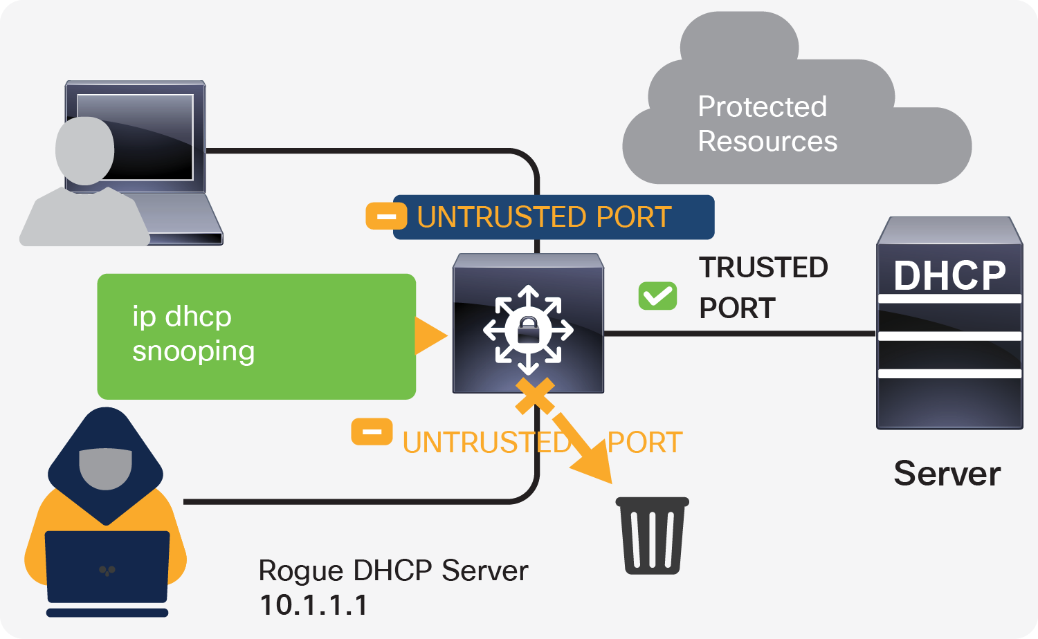
DHCP snooping
One of the common Layer 2 attacks is a rogue DHCP server, which is often used for network attacks such as man-in-the-middle, sniffing, and reconnaissance attacks. The DHCP snooping feature intercepts DHCP messages, rate-limits rogue DHCP traffic from untrusted sources, and builds a DHCP binding table. It determines whether traffic sources are trusted or untrusted. The default trust state of all interfaces is untrusted, and you must configure known internal network interfaces as trusted.
Dynamic ARP inspection
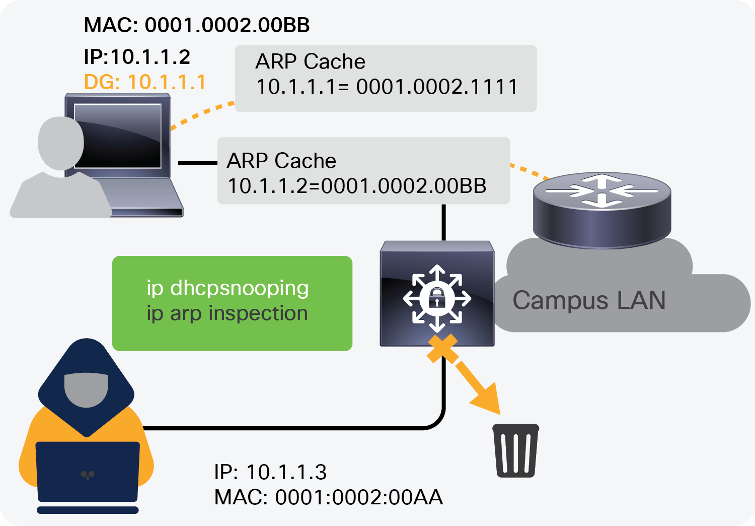
Dynamic ARP inspection
ARP spoofing or poisoning is another common attack observed in Layer 2 segments, where an attacker sends spoofed ARP messages that may allow the attacker to intercept network traffic to gain visibility into it. Dynamic ARP inspection prevents this attack by intercepting all ARP requests and responses via the devices.
IP Source Guard
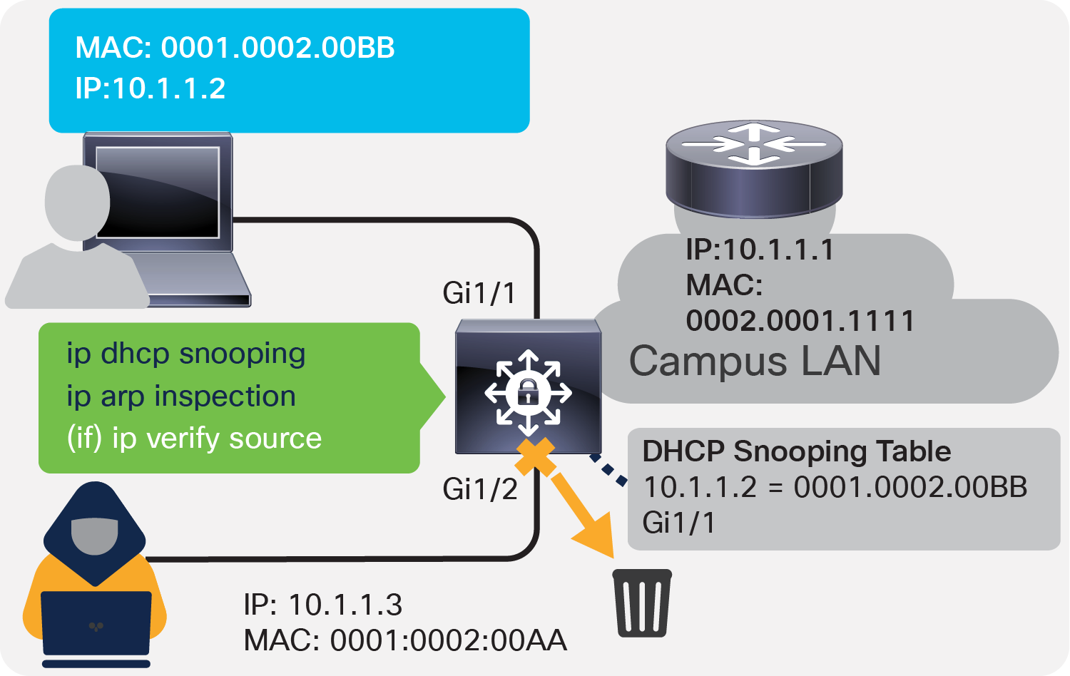
IP Source Guard
IP spoofing or MAC spoofing is another attack through which illegitimate hosts can spoof the IP addresses and MAC addresses of authorized hosts and gain illegal access to the network. IP Source Guard helps to mitigate these attacks by configuring a port ACL for IP addresses and adds MAC addresses to port security based on the DHCP snooping binding table, which in turn blocks the rogue traffic.
The Cisco Catalyst 1000 Series supports AutoSecure, which provides a single-line command to enable baseline security features. When this command is issued, it applies three simple security features:
DHCP snooping
Dynamic ARP inspection
Port security
The single-line command that needs to be enabled on the switch is as follows:
auto security
Based on the port mode, whether access or trunk, this command applies to the host configuration or uplink configuration.
interface GigabitEthernet3/3
description Connected to wired PC
switchport access vlan 11
switchport mode access
auto security-port host
!
interface TenGigabitEthernet1/1
description Trunk Port
switchport mode trunk
auto security-port uplink
The Cisco Catalyst 1000 Series is hardware-ready for PVLAN. Software support can be added in the future. PVLAN, also known as port isolation, helps to partition the Layer 2 broadcast domain of a VLAN into subdomains, allowing you to isolate the ports on the switch from each other. A subdomain consists of a primary VLAN and one or more secondary VLANs. All VLANs in a private VLAN domain share the same primary VLAN.
Types of ports in a private VLAN:
Isolated: Communicates with only promiscuous ports
Promiscuous: Communicates with all other ports
Community: Communicates with the other members of the community and all promiscuous ports
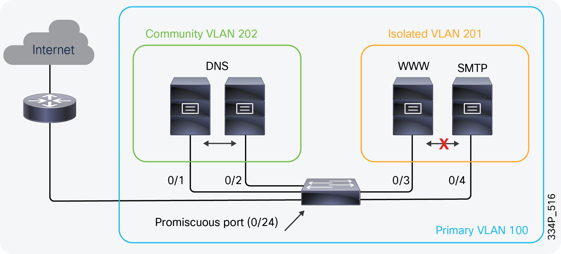
PVLAN
In the configuration shown in Figure 10, the DNS, web, and SMTP servers are in the same VLAN, wherein the DNS servers can communicate with each other and the router, but the web and SMTP servers can communicate only with the router.
As they do with IPv4, the Cisco Catalyst 1000 Series Switches provide integrated IPv6 security features. The IPv6 FHS solution protects networks by mitigating various types of attacks and configuration errors. It addresses IPv6 link operation vulnerabilities, as well as scalability issues in Layer 2 domains.
FHS functionality can be classified in three feature categories: core, advanced, and scalability. Depending on the network requirements, these capabilities can be deployed in a phased manner.
The core set of features provides solid protection from rogue and misconfigured users, and comprise the following:
● RA Guard
● DHCPv6 Guard
● IPv6 Snooping
You can also use Destination Guard, ND Multicast Suppress, etc. for advanced or enhanced performance requirements.
Providing sufficient QoS across IP networks is becoming an increasingly important aspect of today's enterprise IT infrastructure. Not only is QoS necessary for voice and video streaming over the network, it’s also an important factor in supporting the growing IoT. Cisco Catalyst 1000 Series Switches provide flexible mechanisms for marking, classifying, and scheduling to deliver superior performance for data, voice, and video traffic, all at wire speed, thus offering intelligent traffic management that keeps traffic flowing smoothly.
QoS in the Cisco Catalyst 1000 Series
The switches follow the MLS QoS model, and QoS is disabled by default. All the markings are trusted by default, which means that all frames and packets are passed through the switch unaltered.
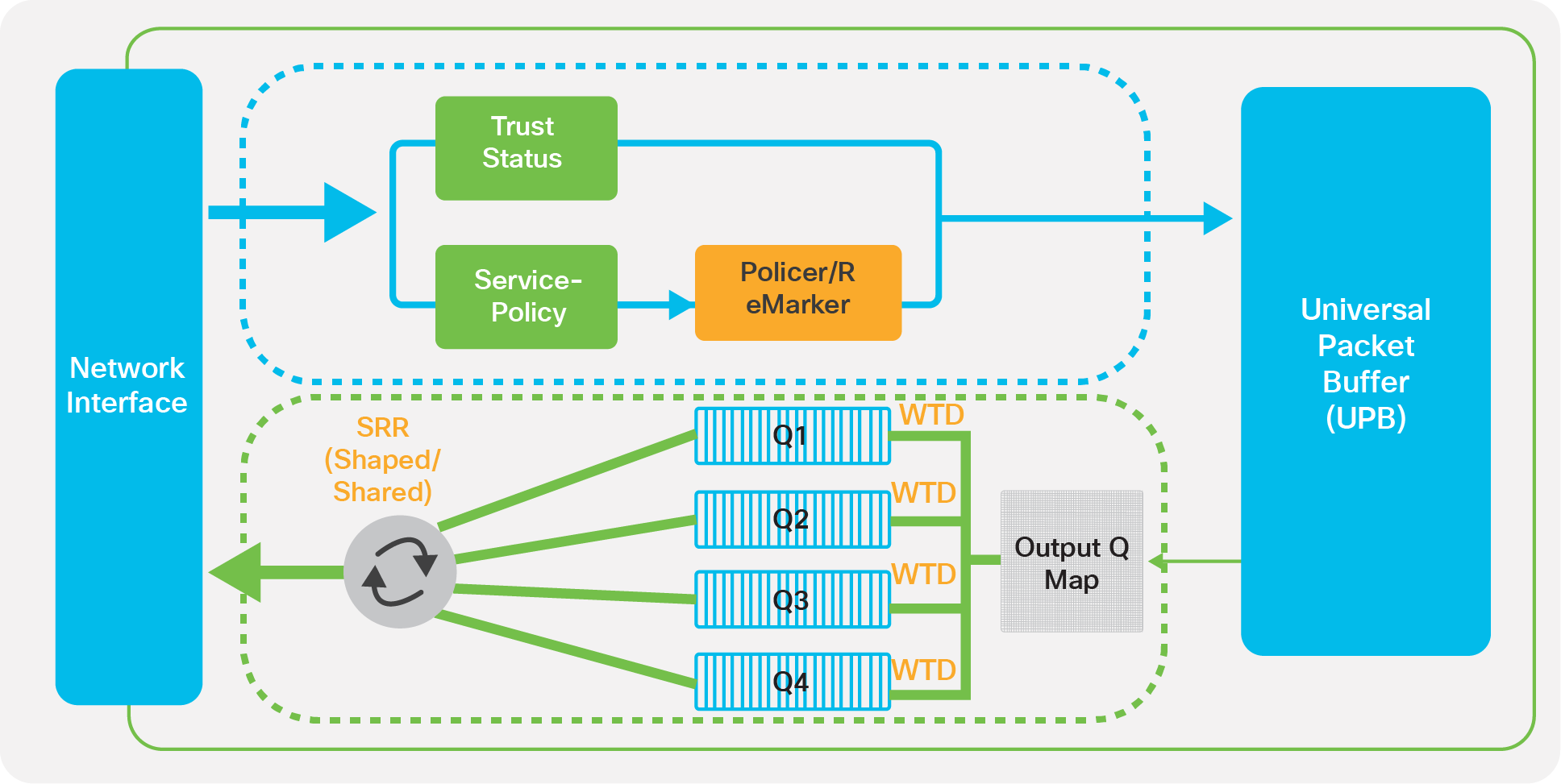
When QoS is enabled, all markings are set to best effort (the Class of Service [CoS] and Differentiated Services Code Point [DSCP] values of the frames that enter the switch are set to 0 by default). You can perform classification, marking, and policing on the ingress side on a per-port basis in a continuous, reliable, and predictable manner for measuring network performance. On the egress side, you can perform egress queuing and scheduling. There are four egress queues per port with three drop threshold per queue, supporting egress bandwidth control, shaping, and priority queuing to help ensure that high-priority packets are serviced ahead of other traffic.
Congestion management and avoidance
Congestion management and avoidance are the egress QoS features supported by Cisco Catalyst 1000 Series Switches. This three-step process involves queueing, dropping, and scheduling. Queueing places the packets into different queues based on their QoS labels. After the traffic is classified and marked with QoS labels, you can assign the traffic into different queues based on the QoS labels.
Weighted Tail Drop (WTD) is used to manage the queue lengths and to provide drop precedence for different traffic classifications.
The egress queues are serviced by Shaped Round Robin (SRR), which controls the rate at which packets are sent. SRR can operate in two modes, called shaped and shared. In shared mode, the queues share the bandwidth among them according to the configured weights. The bandwidth is guaranteed at this level but is not limited to it.
The Cisco Catalyst 1000 Series Switches enable real-time traffic monitoring using standards-based sFlow. sFlow uses a sampling mechanism implemented as an agent on the switch for monitoring the traffic. The sFlow agent periodically samples or polls the interface counters that are associated with a data source of the sampled packets. The data source can be an Ethernet interface or range of Ethernet interfaces.
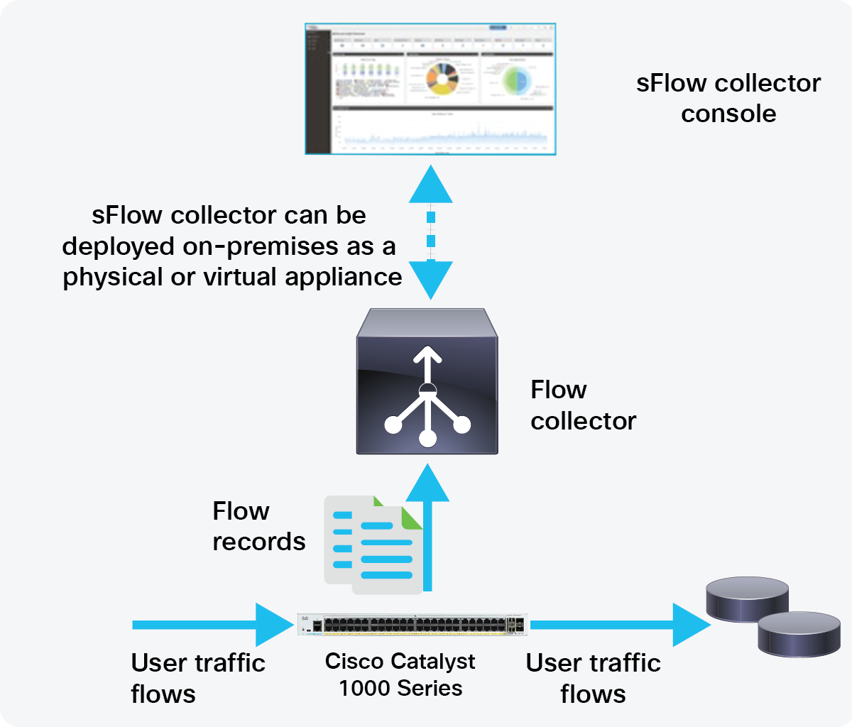
The sFlow process
When you enable sFlow sampling, based on the sampling rate and the hardware internal random number, the ingress packets and egress packets are sent to the CPU as sFlow-sampled packets. The sFlow agent processes the sampled packets and sends an sFlow datagram to the sFlow analyzer. In addition to the original sampled packets, an sFlow datagram includes information about the ingress port, the egress port, and the original packet length. An sFlow datagram can have multiple sFlow samples.
Table 1. sFlow features supported
| sFlow feature |
Cisco Catalyst 1000 Series |
| Flow support |
Ingress/egress |
| Export format |
sFlow version 5 |
| Interface supported |
Physical interfaces only |
| Rate limit |
1000 pps per ASIC |
The Cisco Catalyst 1000 Series also enables monitoring and alerting via the Dying Gasp feature. Dying Gasp is a signal/alert generated when the device is about to go down due to a reset or power failure. The system will hold enough residual power to send out dying gasp messages after a power failure, notifying the administrator or user. The switch can withstand >= 16 ms on detecting a 12V input drop. Additional power is reserved through a capacitor to sustain the CPU and PHY to enable the sending of the dying gasp messages.
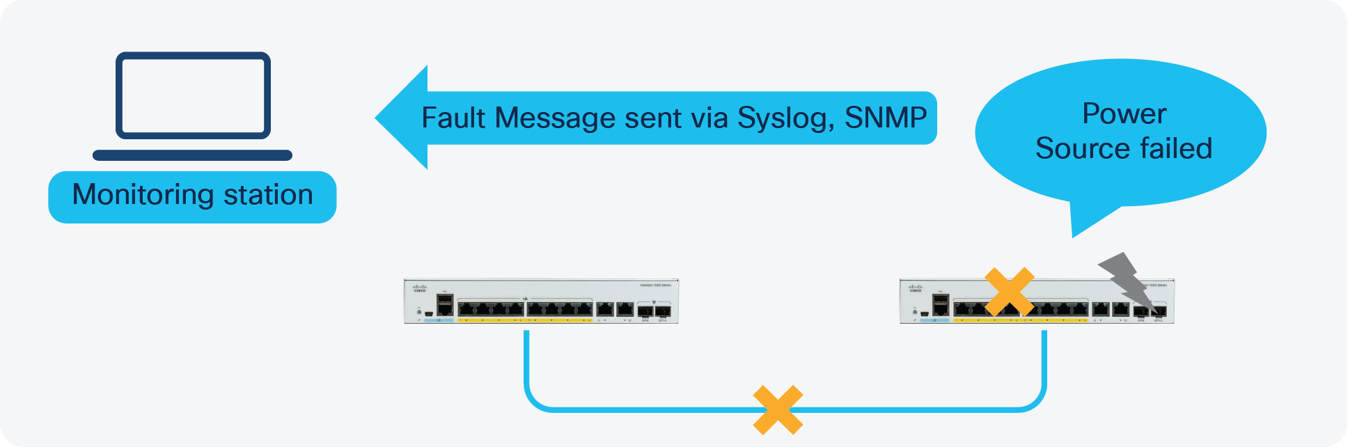
Dying Gasp feature
Dying Gasp packets are created when you configure the host by using the dying-gasp configuration command. The SNMP server for the SNMP dying gasp message is specified through the snmp-server host configuration command. The syslog server sending the syslog dying gasp message is specified through the logging host hostname-or-ipaddress transport udp command.
Configuration required on the switch:
1) Enabling Dying Gasp for the switch:
dying-gasp primary syslog secondary snmp-trap
2) Defining a logging host:
logging host x.x.x.x
3) Specifying an SNMP server
snmp-server enable traps syslog
snmp-server host x.x.x.x version 2c public udp-port xxxx
The new Cisco Catalyst 1000 Series Switches bring Cisco Catalyst quality to small deployments. The switches are fixed, managed Gigabit Ethernet enterprise-class Layer 2 switches providing flexibility, simplicity, and security for smaller deployments.