Cisco Catalyst 8300 and 8200 Series Edge Platforms Architecture White Paper
Available Languages
Bias-Free Language
The documentation set for this product strives to use bias-free language. For the purposes of this documentation set, bias-free is defined as language that does not imply discrimination based on age, disability, gender, racial identity, ethnic identity, sexual orientation, socioeconomic status, and intersectionality. Exceptions may be present in the documentation due to language that is hardcoded in the user interfaces of the product software, language used based on RFP documentation, or language that is used by a referenced third-party product. Learn more about how Cisco is using Inclusive Language.
Cisco launched the Cisco Catalyst 8300 and 8200 Series Edge Platforms between October 2020 and April 2021. These platforms are highly capable and purpose-built to address traditional WAN and emerging SD-WAN solutions, with many branch deployment use cases such as high-speed multicloud access, advanced wireless WAN capabilities, integrated compute and storage, and multilayer security with accelerated SD-WAN services. This white paper will dive deep into the architecture of the Catalyst 8300 and 8200 Series and key building blocks. Awareness of platform architecture will enable you to design best-in-class networks using these platforms.
Introduction to the Catalyst 8300 and 8200 Series
The Catalyst 8300 Series Edge Platforms come in a one- or two-rack-unit modular form factor for medium- to large-scale enterprise branch deployments. There are four models available:
● C8300-2N2S-4T2X
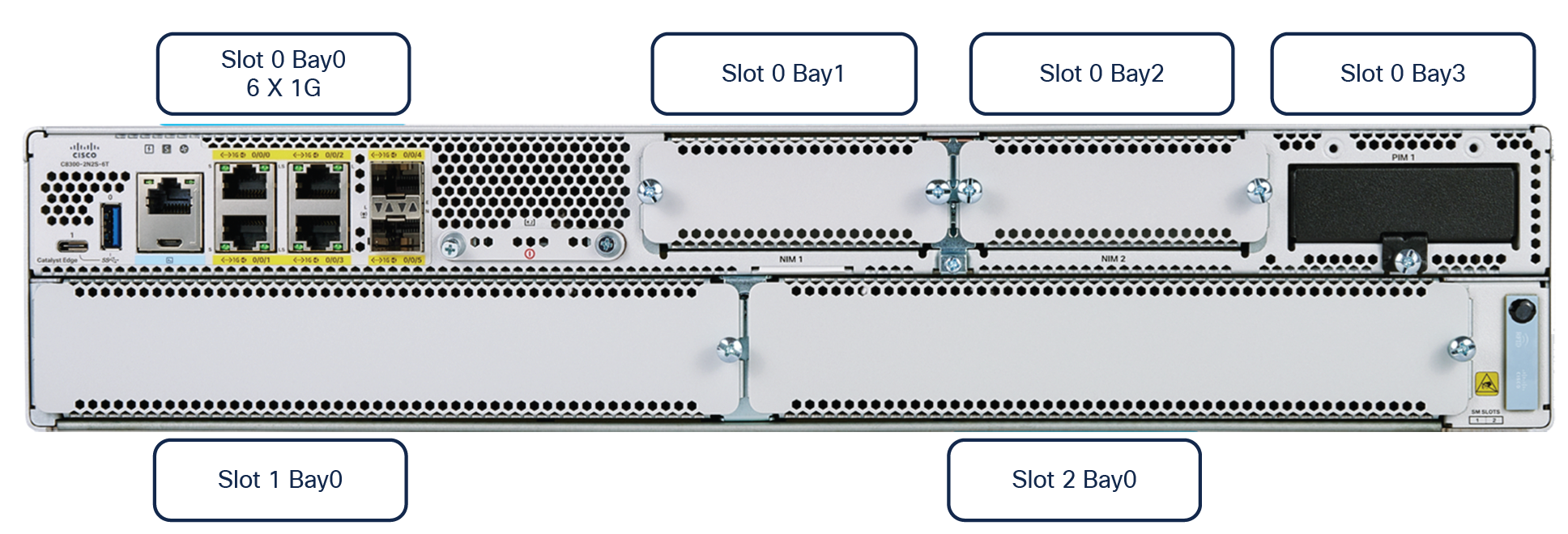
● C8300-2N2S-6T
● C8300-1N1S-4T2X
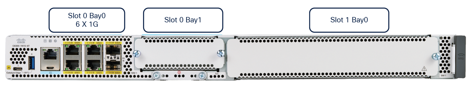
● C8300-1N1S-6T
The Catalyst 8300 Series is built on an x86 System-On-Chip (SoC) multicore CPU system architecture (8 or 12 cores) and is designed for interface flexibility and modularity with six built-in WAN ports, one or two Network Interface Module (NIM) slots, one or two Service Module (SM) slots, and one dedicated Pluggable Interface Module (PIM) slot.
The Catalyst 8200 Series Edge Platforms come in a one-rack-unit modular form factor for small- to medium-scale enterprise branch deployments. There are two models available:
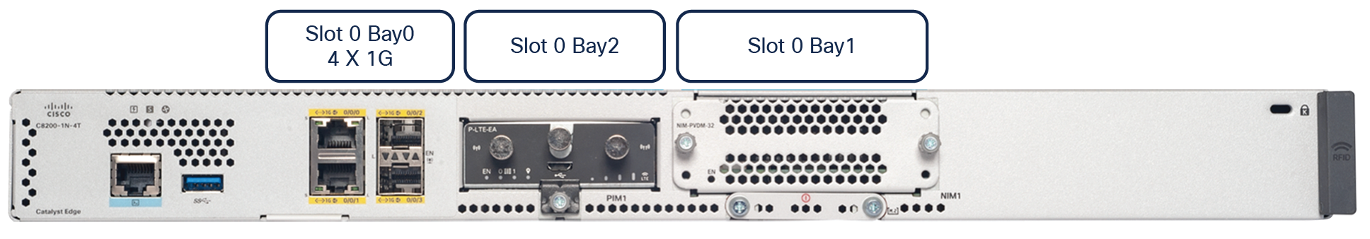
● C8200-1N-4T
● C8200L-1N-4T
The Catalyst 8200 Series is built on an x86 SoC multicore CPU system architecture (four or eight cores) and is designed for interface flexibility and modularity with four built-in WAN ports, one NIM slot, and one dedicated PIM slot.
New components, the open-source Data Plane Development Kit (DPDK) framework and Intel QuickAssist Technology (QAT) engine, have been introduced in the Catalyst 8300 and 8200 Series x86 core architecture to boost the data plane performance for Cisco Express Forwarding, crypto IPsec traffic, and other data plane features.
The Catalyst 8300 and 8200 Series support dynamic core allocation capability — one of the key data path innovations in SoC architecture platforms. This capability enables flexibility for productively using the CPU cores based on the needs of service-focused or data plane-focused deployment models.
The Catalyst 8300 Series Edge Platforms include the following components:
● Six built-in WAN ports with 10G/1G connectivity
● Interface flexibility supporting more than 70 different modules
● Up to 32-GB DRAM scalability
● Up to 600-GB M.2 NVMe storage capacity
● Two external USB 3.0 (Type A and Type C) interfaces
● QAT engine and DPDK framework
● Dedicated PIM slot for LTE and 5G
● Dual redundant AC or DC power supplies
● Removable fan assembly
● On/off switches on the power supplies (AC and DC)
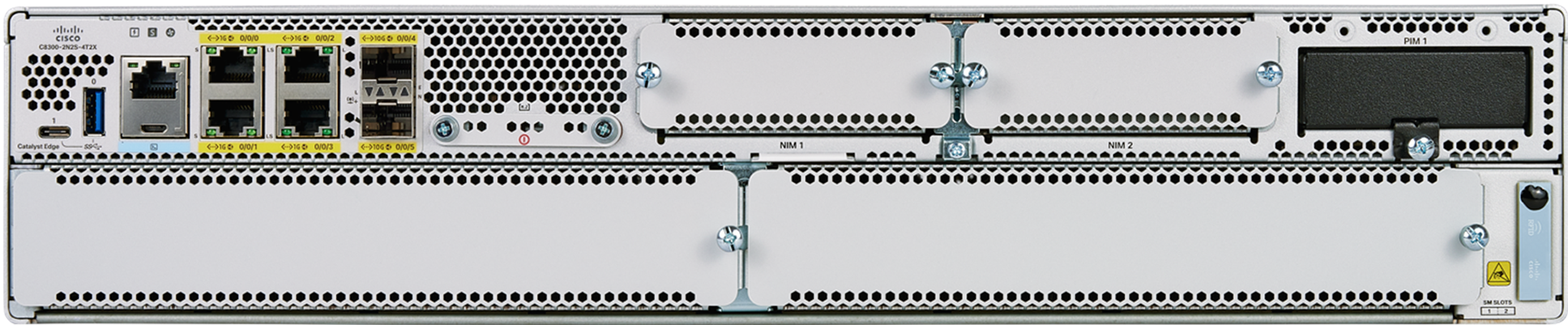
C8300-2N2S-4T2X model
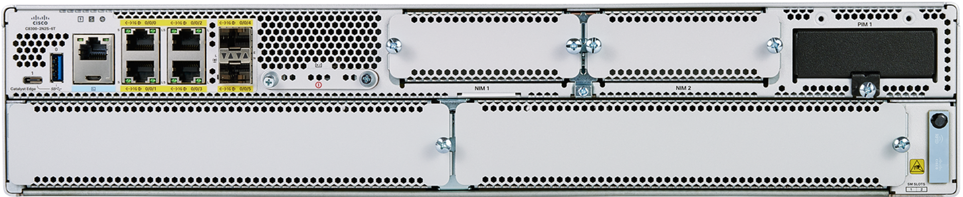
C8300-2N2S-6T model
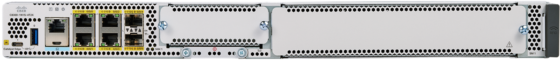
C8300-1N1S-4T2X model
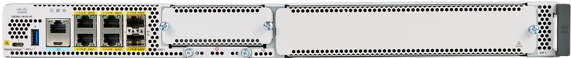
C8300-1N1S-6T model
The Catalyst 8200 Series Edge Platforms include the following components:
● Four built-in WAN ports with 1G connectivity
● Interface flexibility supporting more than 50 types of modules
● Up to 32-GB DRAM scalability
● Up to 600-GB M.2 NVMe storage capacity
● External USB 3.0 (Type A) interface
● QAT engine and DPDK framework
● Dedicated PIM slot for LTE and 5G
● Single AC power supply unit with optional external Power over Ethernet (PoE) adapter
● On/off switch on the power supply (AC only)
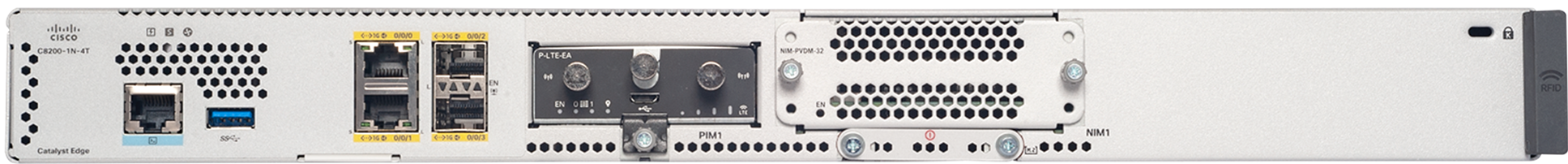
C8200-1N-4T model
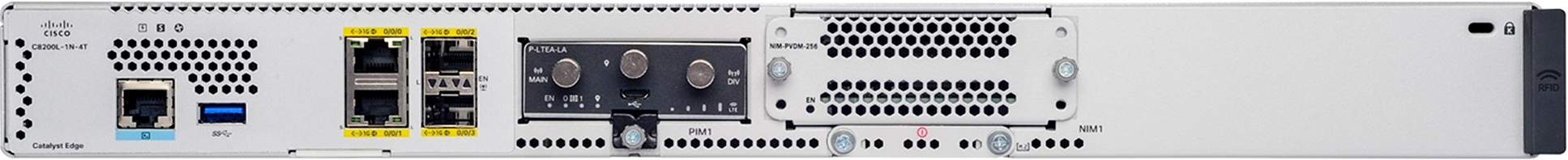
C8200L-1N-4T model
To understand the Catalyst 8300 and 8200 Series, you need to understand the key building blocks. The most important of these are the DPDK framework and QAT engine, which enable the powerful data plane for the platforms, for performance that is two to five times better than the Cisco 4400 and 4300 Series Integrated Services Routers.
The figures below depict the CPU core allocation on an 8-core platform in service-optimized (default) and data-optimized modes with dynamic core allocation features as the key data path innovation.
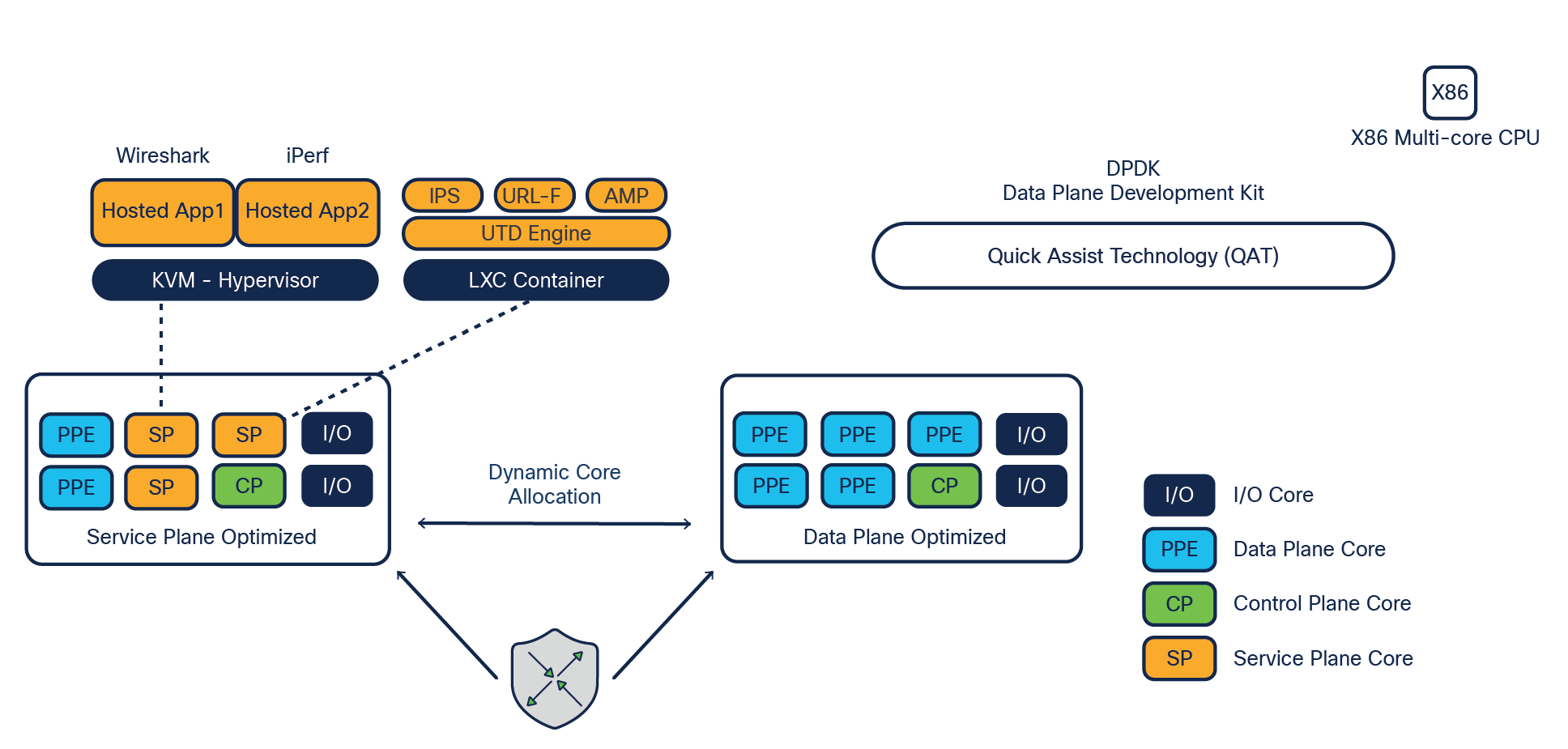
Dynamic core allocation of the Catalyst 8300 and 8200 Series
Catalyst 8300 Series core allocations
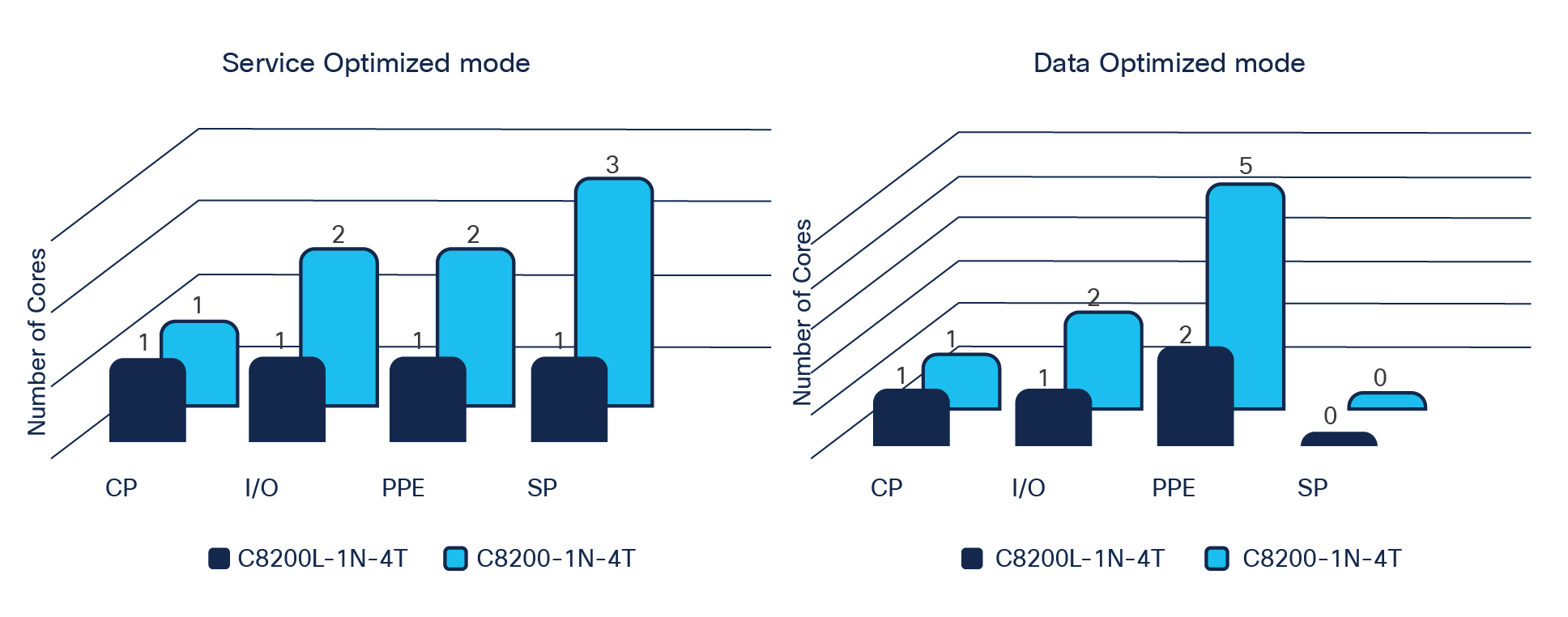
Catalyst 8200 Series core allocations
The dynamic core allocation feature will benefit you in many ways. It will allow you to allocate more cores for the data plane or service plane based on your use cases. For example, if your intention is to run application services as hosted services within the router, you can let the system boot up in the default service-optimized mode and run the services in either KVM or LXC containers. If you do not have hosted services in your deployment, you can repurpose the service cores to data plane operations, thus allocating more cores for feature processing and improving the performance of the data plane features. This flexibility is achieved with a single command executed directly on the platform terminal or from the centralized orchestration platform such as vManage. This feature is supported in both traditional and SD-WAN modes of operation.
Some of the services and applications that can be run inside the platform Cisco IOx containers are:
● Unified Threat Defense (UTD), which includes intrusion prevention, URL filtering, AMP, and Cisco Secure Malware Analytics (formerly Threat Grid)
● Application Quality of Experience (AppQoE) features such as TCP optimization, Forward Error Correction (FEC), packet duplication, Data Redundancy Elimination (DRE), and caching
● SSL/TLS proxy
● Any third-party KVM-based applications such as Wireshark, iPerf, Kiwi Syslog Server, and more
The Catalyst 8300 and 8200 Series Edge Platforms are built on x86 SoC multicore CPUs.
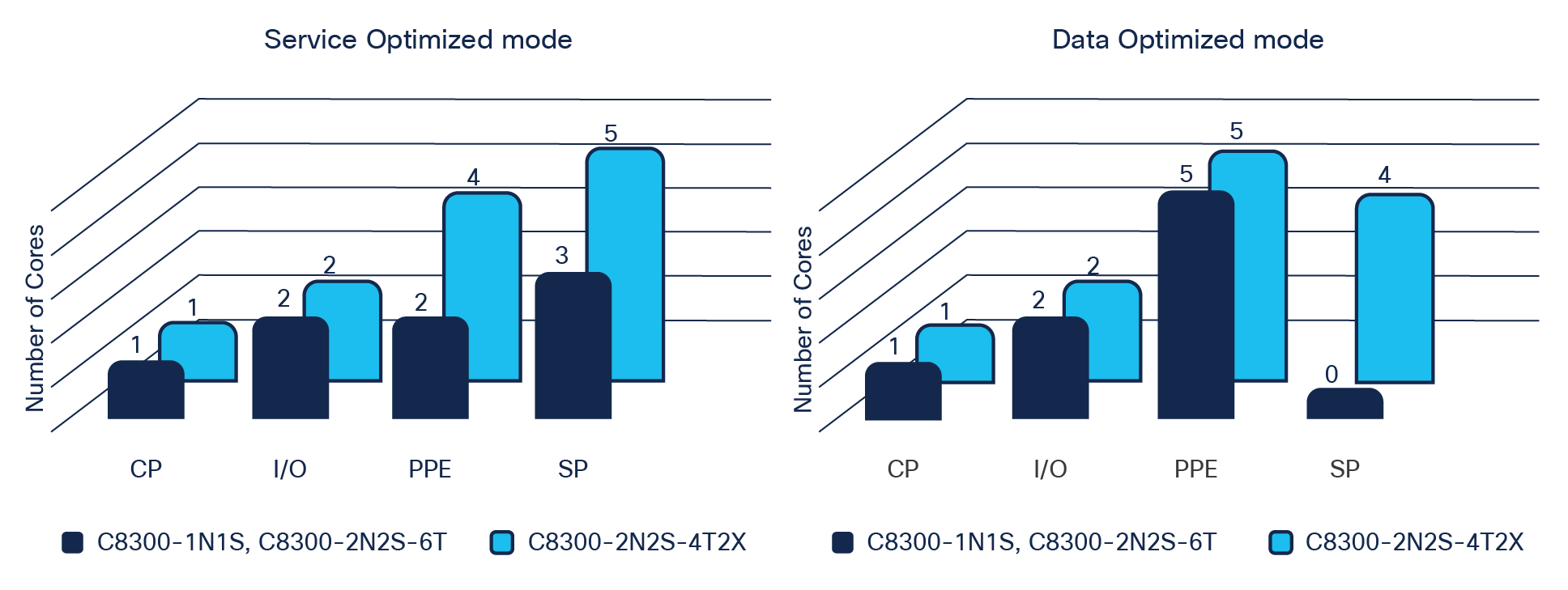
On an 8-core system (C8300-2N2S-6T, C8300-1N1S-4T2X, C8300-1N1S-6T, and C8200-1N-4T) with the default service-optimized mode, four cores are allocated to the data plane for buffering, queuing, scheduling, and feature processing. In data-optimized mode, all three service plane cores are repurposed or turned on as data plane cores, thus allocating seven cores to the data plane for buffering, queuing, scheduling, and feature processing.
On a 12-core system (C8300-2N2S-4T2X) in data optimized mode, a maximum of seven cores can be allocated to the data plane, while four cores are still available for the service plane.
These platforms have been designed with four goals in mind: scale, performance, feature velocity and versatility, and multigenerational longevity.
The Cisco x86 SoC CPU architecture includes the following principal components:
Packet Processing Engine (PPE): The PPE is a prominent part of the data plane core architecture. The main operational functionality of the PPE is packet processing. In an 8-core system (8300 or 8200 Series), two or five cores are dedicated for PPE functionality, depending on whether service or data plane mode is enabled on the platform. In a 12-core system (8300 Series only), there are four or five cores for PPE functionality, depending on whether service or data plane mode is enabled on the platform. Having multiple PPEs provides a massive amount of parallel processing, reducing any requirements for external service blades inside the platform. The assigned PPE is responsible for the packet for its entire life in on-chip memory before it is sent to the traffic manager for scheduling. Each PPE has access to an array of hardware-assist functions such as Layer 1 and Layer 2 cache for feature acceleration of network address and prefix lookups, hash lookups, Weighted Random Early Detection (WRED), traffic policers, range lookups, advanced classification, and access control lists. In situations where flows need to be controlled, a lock manager assures the proper packet ordering for flows. Another key resource for the data plane is the off-chip cryptographic engine (QAT engine), which is accessible from each PPE to speed up the cryptographic encryption and decryption packet processing.
Buffering, Queuing, and Scheduling (BQS): A dedicated flexible queuing engine offers a dramatic offload of BQS processing to address the very complex subscriber- and interface-level queuing requirements of both enterprise and carrier networks. When packet processing is completed, the PPE thread releases the packet to the traffic manager. It is here that any operations related to actual queue scheduling occur. The traffic manager implements an advanced real-time flexible queuing hardware with 16,000 queues and the ability to set three parameters for each queue for maximum bandwidth, minimum bandwidth, and excess bandwidth. In addition, two priority queues can be enabled for each Quality-of-Service (QoS) policy applied. The traffic manager can schedule multiple levels of hierarchy in one pass through the chip with priority propagation through the hierarchy.
Highly programmable forwarding: A software architecture based on a full ANSI-C development environment implemented in a true parallel processing environment, allowing new features to be added quickly as customer requirements evolve by taking advantage of industry-standard tools and languages built upon a powerful parallel processing architecture. This architecture represents a paradigm shift and evolution in the software architectures associated with network processing today.
Data Plane Development Kit (DPDK): The Catalyst 8300 and 8200 Series Edge Platforms leverage new DPDK libraries to grant user processes access to the network interface controller I/O entities. The Polling-Mode Drivers (PMDs) enable feature execution without the need for a system call. This vital improvement in implementation has bumped the IP Cisco Express Forwarding performance up to 20 Gbps for 1400 bytes and 12 Gbps with IMIX (352-byte) packet payloads on the 8300 Series and up to 4 Gbps for 1400 bytes and 3.8 Gbps with IMIX (352-byte) packet payloads on the 8200 Series.
Intel QuickAssist Technology (QAT): QAT is enabled on the Catalyst 8300 and 8200 Series Edge Platforms in the multicore x86 implementation. It has dramatically boosted the security and compression acceleration to enable us to derive up to 19 Gbps crypto throughput for 1400 bytes and 5 Gbps IMIX (352-byte) packet payloads on the 8300 Series and up to 1 Gbps crypto throughput for 1400 bytes and IMIX (352-byte) packet payloads on the 8200 Series.
The Catalyst 8300 and 8200 Series Edge Platforms have a built-in control plane to establish route processor functionalities.
The control plane implementations are responsible for the following functions:
● Running of the router control plane, including network control packets and connection setup.
● Management of the Routing Information Base (RIB or routing table).
● Master and standby (includes switchover from a failing master to the standby).
● Code storage, management, and upgrade.
● Onboard Failure Logging (OBFL).
● Downloading of operational code for interface control blocks, and forwarding processors.
● Command-Line Interface (CLI), alarm, network management, logging, and statistics aggregation.
● Punt path to the data plane cores for packet processing.
● Configuration repository along with logging system statistics, records, events, errors, and dumps of the management interfaces of the platform, including the console serial port. The CLI, status indicators, Background Intelligent Transfer Service (BITS) interface, reset switch, Audible Cutoff (ACO) button, USB ports for secure key distribution, and micro-USB console.
● Field-replaceable fan tray and power supply module Online Insertion and Removal (OIR) events.
● Chassis management, including activation and initialization of the line cards or modules, image management and distribution, logging facilities, distribution of user configuration information, and alarm control.
● Control signals for monitoring the health of power entry modules, shutting down the power, and driving alarm relays located on the power entry modules.
● Software redundancy — high availability.
Let’s have a look at how the building blocks fit together to construct the 8300 Series platforms.
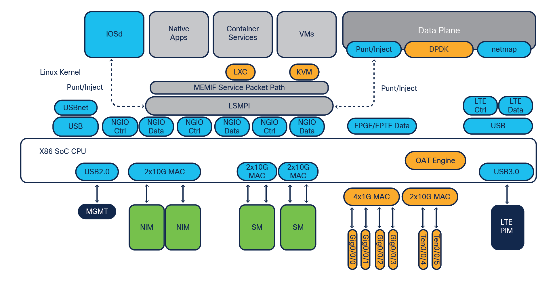
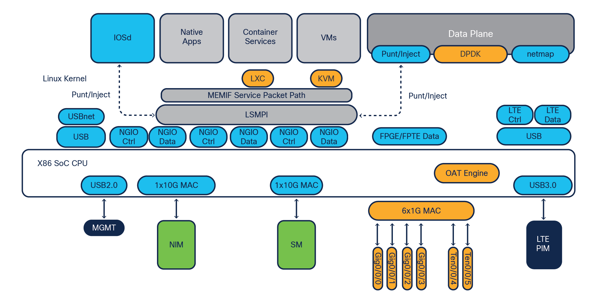
C8300-2N2S-4T2X system block diagram
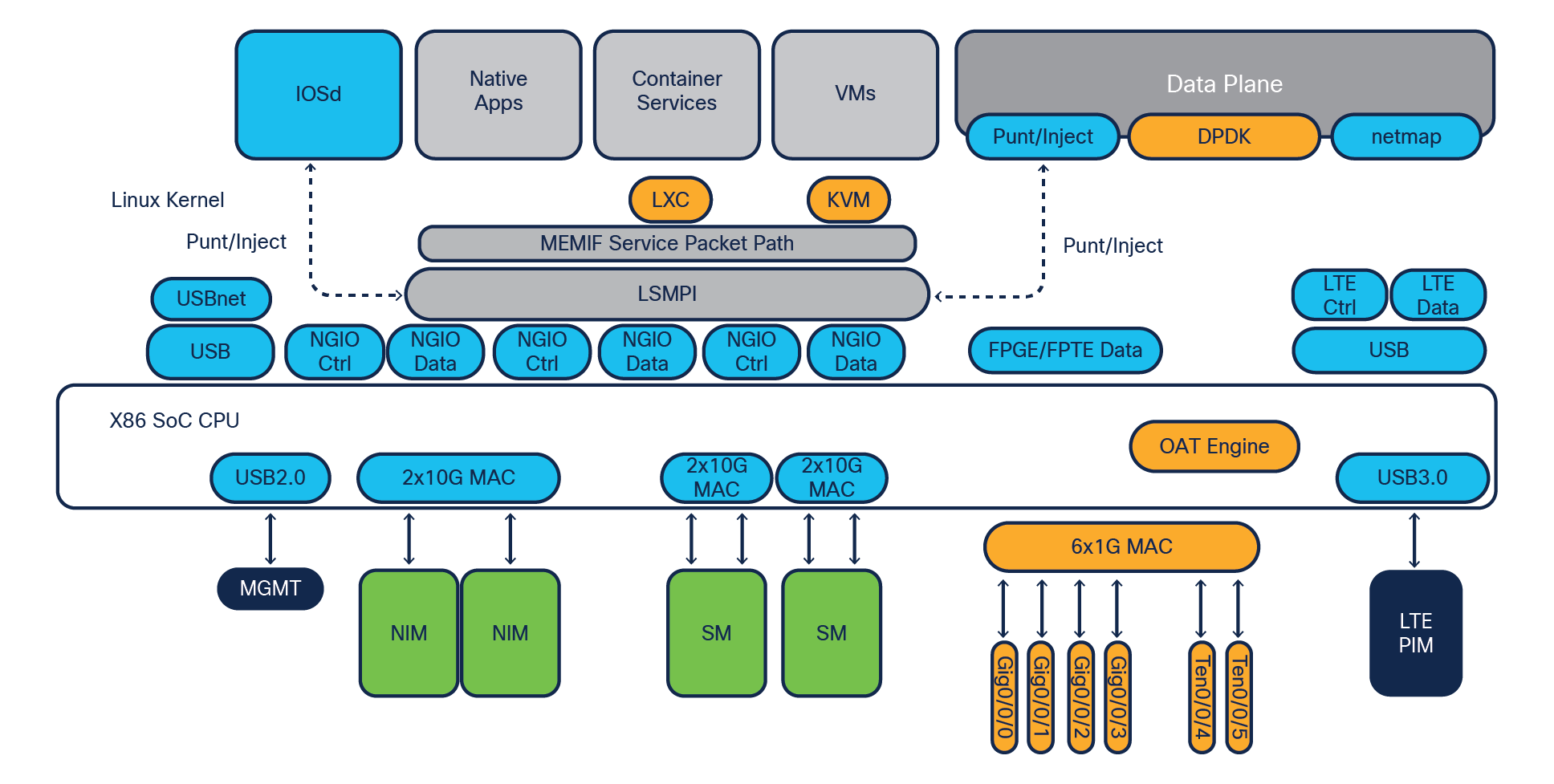
C8300-2N2S-6T system block diagram
The major difference between the C8300-2N2S-4T2X and C8300-2N2S-6T is the front panel ports. The C8300-2N2S-4T2X supports two 10G ports, and the C8300-2N2S-6T supports only 1G ports.
C8300-1N1S-4T2X system block diagram
C8300-1N1S-6T system block diagram
The important hardware entities within the Catalyst 8300 Series system are:
● Single-core control plane on the x86 processor, which runs IOSd and other required system processes.
● Four or six cores for data plane feature processing, with the ability to allocate seven cores using data plane mode for improved data plane throughput.
● DPDK for a fast packet processing ecosystem that operates in Linux user space. This framework provides a set of libraries that enable a general abstraction layer for packet buffers, system memory allocation and deallocation, hash algorithms for longest prefix match, and more. The data plane performance is boosted to between 10 and 12 Gbps with a 352-byte average IMIX packet size.
● QAT engine for cryptographic and compression acceleration for faster encryption and decryption by offloading it from the data plane cores. The IPsec performance is boosted to between 2 and 5 Gbps with a 352-byte average IMIX packet size.
● 10G backplane connectivity directly to the data plane CPU cores from the NIM and SM slots.
● More WAN ports, with 6G ports or 4G and two 10G ports available on the front panel I/O.
● USB 3.0 interface between the LTE PIM slot and data plane cores for high-speed cellular connections.
● Chassis management block helps manage the overall chassis hardware components and their interrupts for smooth operation of the platform.
● Up to 32-GB DRAM support for services and application hosting in the LXC and KVM form factor and higher feature scale.
Let’s have a look at how the building blocks fit together to construct the Catalyst 8200/L Series platforms.
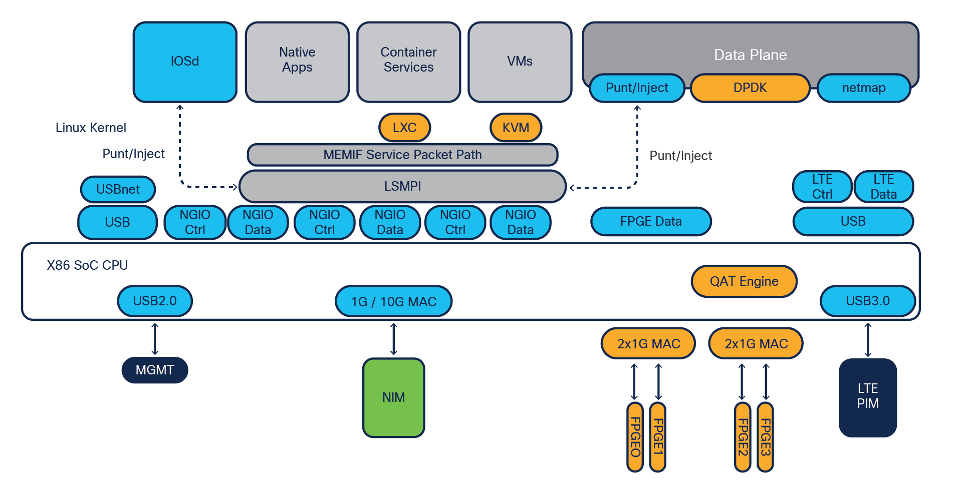
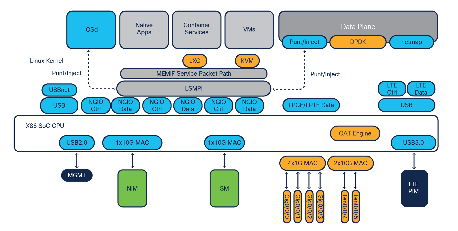
C8200-1N-4T and C8200L-1N-4T system block diagram
Note: The LXC and KVM container services do not apply to the C8200L-1N-4T model.
The important hardware entities within the Catalyst 8200 Series system are:
● Single-core control plane on the x86 processor, which runs IOSd and other required system processes.
● Three or four cores for data plane feature processing, with the ability to allocate seven cores using data plane mode for improved data plane throughput.
● DPDK for a fast packet processing ecosystem that operates in Linux user space. This framework provides a set of libraries that enable a general abstraction layer for packet buffers, system memory allocation and deallocation, hash algorithms for longest prefix match, etc. The data plane performance is boosted to 3.8 Gbps, with a 352-byte average IMIX packet size.
● QAT engine for cryptographic and compression acceleration for faster encryption and decryption by offloading it from the data plane cores. The IPsec performance is boosted to between 500 Mbps and 1 Gbps, with a 352-byte average IMIX packet size.
● 1G/10G backplane connectivity directly to the data plane CPU cores from the NIM slot. 10G backplane on C8200 and 1G backplane on C8200L platforms.
● More WAN ports, with 4G ports available on the front panel I/O.
● USB 3.0 interface between the LTE PIM slot and data plane cores for high-speed cellular connections.
● Chassis management block helps manage the overall chassis hardware components and their interrupts for smooth operation of the platform.
● Up to 32-GB DRAM support for services and application hosting (LXC and KVM) and higher feature scale.
The Catalyst 8300 and 8200 Series Edge Platforms honor centralized forwarding with an x86 SoC multicore architecture. The data plane makes all the forwarding decisions by synchronizing the routing information from the control plane Routing Information Base (RIB) and building a forwarding table called the Forwarding Information Base (FIB).
The following steps elaborate on the details of the packet flow:
1. Layer 1 checks at the interface PHY are processed at the built-in interface receive (Rx) path, and then packets get handed over to the data plane, which also handles the DPDK framework.
2. Layer 2 packet validations such as Cyclic Redundancy Check (CRC), maximum transmission unit (MTU), and runt errors are checked on the integrated MAC on the PHY itself.
3. If the interface is enabled with MACsec, the learned key packet will be decrypted based on the MACsec Key Agreement (MKA). This is applicable if MACsec is enabled during configuration.
4. When the packets are received on the front panel GE/TE ports, they will arrive at kernel space GE/TE drivers. DPDK PMDs will directly poll packets to data plane Rx processes, which enqueues them for distribution.
5. When the packets are received on the NIM/SM (next-generation I/O or NGIO) modules, the host MAC splits the NGIO control packets and the non-NGIO packets to the control plane CPU core based on the VLAN ID and priority code point (PCP) field. The packets to the data plane are steered to three different queues — NGIO Control, NGIO High-Priority (HP) Data, and NGIO Low-Priority (LP) Data — based on the VLAN ID and PCP field. The data plane implements strict priority among these queues. For the egress packet flow, the module MAC steers the packet into four different queues — NGIO Control, NGIO HP1 Data, NGIO HP2 Data, and NGIO LP Data — based on the VLAN ID and PCP field. The outbound interface driver ensures strict priority among these queues.
6. Packets are stored in the packet buffer queue and then dispatched to the packet processing engines for feature processing and forwarding.
7. If the packet needs to be encrypted or decrypted (IPsec), it gets handed over to the crypto engine (QAT) prior to further processing.
8. The crypto operation is done entirely within the crypto engine, which is equipped with dedicated compute and memory for cipher and digest algorithm application.
9. After the ingress features are applied on the packet, FIB lookup happens to figure out the egress path. The packets are then enqueued for an egress operation based on the configured Feature Invocation Arrays (FIAs).
10. After egress FIA processing, the packet gets copied to the packet buffer memory for further queuing and scheduling by the I/O cores.
11. The I/O cores schedule the packets based on modular QoS configurations; the packets are enqueued in the output buffers.
12. If the interface is enabled with MACsec, the learned key packet will be encrypted based on the MKS.
13. The Layer 2 processing will happen in the data plane for egress processing at the MAC layer and sends the packet toward the exit interface.
14. Post-Layer 1 processing is done at the egress interface; the packet exits toward the next hop.
The Cisco IOS XE modular implementation at the control and data plane level, from Layer 2 to Layer 7 feature processing, makes sure that the packets are treated based on the configuration and that the services get applied one by one. At every stage, required flow control makes sure congestion situations are handled gracefully, treating high-priority traffic ahead of low-priority traffic.
The following are key points for the various types of packet processing:
● When unicast Cisco Express Forwarding packets reach the data plane, the ingress features are applied first, followed by FIB lookup and then the egress features, as per the exit interface configuration.
● The multicast packet replication for 1:N multicast happens within the data plane level. Post-replication, the replicated packets complete FIB lookup and are forwarded toward the egress interface.
● All crypto traffic is processed in the QAT engine for encryption and decryption. QAT crypto engines take care of hardware-accelerated crypto functions, with inline implementation making it more effective.
● Traffic destined for the control plane will get punted by the data plane to the IOSd process running on the single-core CPU. The IOSd process generated and response packets get injected into the data plane for forwarding to the egress direction post-FIB lookup.
The Catalyst 8300 and 8200 Series Edge Platforms are designed to allow ingress oversubscription.
In the case of the C8300-2N2S-4T2X and C8300-1N1S-4T2X platforms, a maximum of 12 Gbps of Cisco Express Forwarding traffic aggregation is possible. Various port configuration options are available in 1G, 2.5G, and 10G.
In the case of the C8300-2N2S-6T and C8300-1N1S-6T platforms, a maximum of 10 Gbps of Cisco Express Forwarding traffic aggregation is possible. Various port configurations options are available in 1G, 2.5G, and 10G.
In the case of the C8200-1N-4T and C8200L-1N-4T platforms, a maximum of 3.8 Gbps of Cisco Express Forwarding traffic aggregation is possible. Various port configurations options are available in 1G and 2.5G.
1G/10G WAN MACsec is possible on the Enhanced Small Form-Factor Pluggable (SFP+) built-in ports or using the C-NIM-1X 10G WAN module on the Catalyst 8300 Series Edge Platforms. The C-NIM-2T module will provide a 1G WAN MACsec option on both the Catalyst 8300 and 8200 Series Edge Platforms.
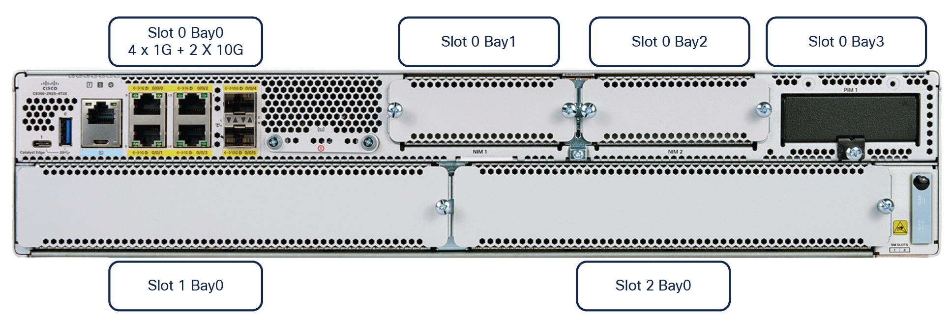
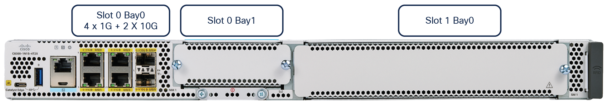
C8300-2N2S-4T2X and C8300-1N1S-4T2X connectivity options
Example: GigabitEthernetSlot0/Bay0/Port0 is GigabitEthernet0/0/0
GigabitEthernetSlot1/Bay0/Port0 is GigabitEthernet1/0/0
Table 1. Catalyst 8300-2N2S-4T2X and 8300-1N1S-4T2X platform offerings for WAN Ethernet
| Port type |
Number of ports/modules |
| 10G |
2 onboard SFP+ (MACsec on SFP+ ports on C8300-2N2S-4T2X), 1 or 2 ports with NIM with WAN MACsec, 2 or 4 ports with NIM on SM carrier card with WAN MACsec |
| Multigigabit (2.5G) |
1 or 2 ports with NIM, 2 or 4 ports with SM carrier card module with NIM with WAN MACsec (from Release 17.6 of Cisco IOS XE) |
| 1G |
6 onboard ports (4 RJ-45 + 2 SFP+), 1 or 2 ports with NIM with WAN MACsec, 2 or 4 ports with modules on SM carrier card with WAN MACsec |
Note: The 1G or 10G port speed is auto-detected based on the SFP or SFP+ used in the port.
Table 2. Catalyst 8300-2N2S-4T2X and 8300-1N1S-4T2X platform offerings for LAN Ethernet
| Port type |
Number of ports/modules |
| 10G |
2 ports with next-generation switch modules |
| 1G |
8, 16, or 40 ports with next-generation switch modules with LAN MACsec (128-bit) |
| Multigigabit (2.5G) |
4 or 8 ports with next-generation switch modules |
C8300-2N2S-6Tand C8300-1N1S-6T connectivity options
Example: GigabitEthernetSlot0/Bay0/Port0 is GigabitEthernet0/0/0
GigabitEthernetSlot1/Bay0/Port0 is GigabitEthernet1/0/0
Table 3. Catalyst 8300-2N2S-6T and 8300-1N1S-6T platform offerings for WAN Ethernet:
| Port type |
Number of ports/modules |
| 10G |
1 or 2 ports with NIM with WAN MACsec, 2 or 4 ports with NIM on SM carrier card with WAN MACsec |
| Multigigabit (2.5G) |
1 or 2 ports with NIM, 2 or 4 ports with SM carrier card module with NIM with WAN MACsec (from Release 17.6 of Cisco IOS XE) |
| 1G |
6 onboard ports (4 RJ-45 + 2 SFP), 1 or 2 ports with NIM with WAN MACsec, 2 or 4 ports with NIM on SM carrier card with WAN MACsec |
Note: The 1G or 10G port speed is auto-detected based on the SFP or SFP+ used in the port.
Table 4. Catalyst 8300-6T platform offerings for LAN Ethernet
| Port type |
Number of ports/modules |
| 10G |
2 ports with next-generation switch modules |
| 1G |
8, 16, or 40 ports with NIM and next-generation switch modules with LAN MACsec (128-bit) |
| Multigigabit (2.5G) |
4 or 8 ports with next-generation switch modules |
C8200-1N-4T and C8200L-1N-4T connectivity options
Example: GigabitEthernetSlot0/Bay0/Port0 is GigabitEthernet0/0/0
Table 5. Catalyst 8200 Series platform offerings for WAN Ethernet
| Port type |
Number of ports/modules |
| 1G |
4 onboard (2 RJ-45 + 2 SFP), 2 ports with NIM (from Release 17.6 of Cisco IOS XE) |
| Multigigabit (2.5G) |
1 port with NIM (from Release 17.6 of Cisco IOS XE) |
| 1G |
8 Layer 2 ports with NIM |
For a list of modules supported on the Catalyst 8300 and 8200 Series Edge Platforms, refer to the platform data sheet in the “For more information’’ section.
For a list of SFPs compatible with the Catalyst 8300 and 8200 Series Edge Platforms, refer to the URLs below:
8300 Series: https://tmgmatrix.cisco.com/?si=8300
8200 Series: https://tmgmatrix.cisco.com/?si=8200
The Catalyst 8300 Series Edge Platforms support more than 70 different modules in the NIM, SM, and PIM form factors, and the Catalyst 8200 Series Edge Platforms support more than 50 modules in the NIM and PIM form factors.
The Catalyst 8300 and 8200 Series Edge Platforms are equipped with nonupgradable 8 GB of bootflash memory for internal storage and a default of 8 GB of DRAM memory for control plane operation. The DRAM is upgradable to 16 GB or 32 GB. Besides 8 GB of internal storage, both of these platforms come with a default 16-GB M.2 external USB storage module. For additional storage, 32-GB or 600-GB M.2 USB/NVMe options are available.
The C8200L-1N-4T model is equipped with nonupgradable 4 GB of bootflash memory for internal storage and a default of 4 GB of DRAM memory for control plane operation. The DRAM is upgradable to 16 GB or 32 GB. Besides 4 GB of internal storage, this platform comes with a default 16-GB M.2 external USB storage module. For additional storage, 32-GB or 600-GB M.2 USB/NVMe options are available.
For classification feature scale such as Access Control Entries (ACEs), QoS, Network Address Translation (NAT), and firewall, where quick lookups and services application are desired, the control plane DRAM memory is used, along with the route scale and other control plane scale available on the platform.
The Catalyst 8300 Series has a redundant power supply for AC, DC, high-voltage DC (HVDC), and Network Equipment-Building System (NEBS) DC power sources. In the C8300-2N2S-4T2X and C8300-2N2S-6T models, the AC power supplies are 650W and 1000W, whereas the DC power supply is 650W. In the C8300-1N1S-4T2X and C8300-1N1S-6T models, the AC power supplies are 250W or 500W, whereas the DC power supply is 400W. HVDC is supported only on the C8300-1N1S-4T2X and C8300-1N1S-6T models, while the NEBS DC power supply is supported only on the C8300-2N2S-4T2X and C8300-2N2S-6T models.
The two modules work in load-sharing mode to enable 1+1 power supply redundancy. Each power supply module has its own cooling with built-in fans. The DC power supply’s input connector is a 2-wire screw-type connector with connection polarity from left to right (when facing the unit) of positive (+) and negative (–). Both power supply modules adhere to the Platinum power efficiency (≥ 90%) standard.
In the Catalyst 8200 Series, there is only a single default internal power supply system with 100W AC support. A 4-pin DC out connector connects to an external PoE adapter (AC 150W), which is used only for PoE power output from the chassis. This is optional and required only if you have a PoE switch module in the chassis slot to provide PoE power output to the endpoints. The external PoE adapter can provide 150W of PoE power to the chassis.
The fan modules in the C8300-2N2S-4T2X and C8300-2N2S-6T models are field-replaceable. The fan modules in the C8300-1N1S-4T2X, C8300-1N1S-6T, and 8200 Series platforms are not field-replaceable. The C8300-2N2S-4T2X and C8300-2N2S-6T models have four internal fans in total, and the 8300-1N1S-4T2X and C8300-1N1S-6T models have three internal fans in total, which are supplied with power individually from the power source. This helps the platform achieve N+1 redundancy such that, if one of the fans stops working, the remaining fans will continue the cooling function for the chassis.
The C8200-1N-4T and C8200L-1N-4T models have two internal fans in total, and both fans have to be operational for the proper cooling of the chassis. There is no N+1 redundancy on the fans.
The fans in the power supply module are used for cooling the power supply itself, while system-level cooling is provided by the fans within the chassis. The power supply does not depend on the system-level fans for cooling. Fan failure is determined by fan-rotation sensors. The default airflow direction is front to back for the chassis as well as for the power supply fans for AC, DC, and HVDC. For reverse airflow (back to front), the NEBS DC power supply is required.
The Cisco Catalyst 8300 and 8200 Series Edge Platforms are driven by an x86 SoC architecture with a strong data plane, a highly scalable control plane, built-in interface flexibility with options for 10G and 1G, and, most importantly, hardware-accelerated services.
The Catalyst 8300 and 8200 Series offer best-in-class hardware with rich software features for high-performance traditional routing and emerging SD-WAN and small, medium, and large branch use cases.
To learn more about the capabilities of the Catalyst 8300 and 8200 Series Edge Platforms, visit the following:
● Catalyst 8300 Series Data Sheet
● Catalyst 8200 Series Data Sheet
● Catalyst 8300 Series Frequently Asked Questions
● Catalyst 8200 Series Frequently Asked Questions
● Cisco Catalyst TV YouTube channel
Our experts recommend
● Catalyst 8300 Series Edge Platforms FAQ
● Catalyst 8200 Series Edge Platforms FAQ