|
Collaboration Virtualization Sizing
|
||||||||||||||||||||||||||||||||||||||||||||||||||||||||||||||||||||||||||||||||||||||||||||||||||||||||||||||||||||||||||||||||||||||||||||||||||||||||||||||||||||||||||||||||||||||||||||||||||||||||||||
| |
||||||||||||||||||||||||||||||||||||||||||||||||||||||||||||||||||||||||||||||||||||||||||||||||||||||||||||||||||||||||||||||||||||||||||||||||||||||||||||||||||||||||||||||||||||||||||||||||||||||||||||
| Introduction |
||||||||||||||||||||||||||||||||||||||||||||||||||||||||||||||||||||||||||||||||||||||||||||||||||||||||||||||||||||||||||||||||||||||||||||||||||||||||||||||||||||||||||||||||||||||||||||||||||||||||||||
|
This page is intended to help you design a storage system when using any 3rd-party SAN/NAS storage arrays (including use with diskless UCS B-Series TRCs), specs-based DAS hardware (including UCS C-Series DAS configurations not aligned with a TRC) and Cisco HyperFlex. More detail is provided on GB and IOPS capacity planning to meet the requiremetns of Collaboration applications. With Cisco Business Edition 6000/7000 appliances or any of the TRCs with DAS or HperFlex storage, the DAS configuration (e.g. disk technology, quantity, size, speed, RAID configuration) has already been properly designed to provide enough IOPS capacity and performance has been explicitly validated by Collaboration applications. Just follow the normal sizing rules described in Collaboration Virtualization Hardware and Sizing Guidelines such as CPU, memory, and storage capacity requirements.
|
||||||||||||||||||||||||||||||||||||||||||||||||||||||||||||||||||||||||||||||||||||||||||||||||||||||||||||||||||||||||||||||||||||||||||||||||||||||||||||||||||||||||||||||||||||||||||||||||||||||||||||
| |
||||||||||||||||||||||||||||||||||||||||||||||||||||||||||||||||||||||||||||||||||||||||||||||||||||||||||||||||||||||||||||||||||||||||||||||||||||||||||||||||||||||||||||||||||||||||||||||||||||||||||||
| IOPS Capacity and Performance Planning |
||||||||||||||||||||||||||||||||||||||||||||||||||||||||||||||||||||||||||||||||||||||||||||||||||||||||||||||||||||||||||||||||||||||||||||||||||||||||||||||||||||||||||||||||||||||||||||||||||||||||||||
|
Knowing the IOPS (In/Out Operations per second) utilization of the Cisco Collaboration applications ahead of time will help you design a storage array that will meet the storage latency and performance requirements of Collaboration applications. To find information on the IOPS characterization for a specific Cisco Collaboration application, go the home page http://www.cisco.com/go/virtualized-collaboration, in the "At a Glance - Cisco Virtualization Support" section, click on that specific Collaboration application, and look for the "IOPS and Storage System Performance Requirements" section. IOPS requirements for the storage array is done by using the sum of Collaboration application VM's IOPS. Note that with DAS, addressing IOPS requirements may require higher disk/spindle counts, which may result in excess storage capacity beyond minimum needed for the Collaboration applications. The storage performance should be monitored so that the latency and storage performance requirements are met at all time.
Example
IOPS calculation example
In this example, the deployment includes CUCM, IM & Presence, Unity Connection. Assumptions: 12,000 users/devices, 4 BHCA per user, No CUCM CDR Analysis and Reporting, one application upgrade at a time, one application DRS backup at a time.
Design:
CUCM IOPS calculation
PUB and TFTP nodes: Consider the total BHCA for the cluster for the purpose of sizing, 12,000 users x 4 BHCA = 48,000 BHCA. Subscriber nodes: 6,000 users per Subscriber pair, assuming 1:1 redundancy. So 24,000 BHCA per CUCM subscriber pair or an average of 12,000 BHCA per CUCM subscriber. From the IOPS characterization in the CUCM docwiki page, a CUCM node handling between 10k and 25k BHCA produces 50 IOPS. A CUCM node handling between 25k and 50k BHCA produces 100 IOPS. Hence the table below.
IM & Presence calculation
From the IOPS characterization in the IM & Presence docwiki page, IOPS are about 160 when using an OVA with more than 1,000 users.
Unity Connection IOPS calculation
The IOPS characterization in the Unity Connection docwiki page provides information on the IOPS per node when using the 7 vCPU OVA, refer to the first data column below. We can then calculate the other numbers in the following columns.
MediaSense IOPS calculation
Below are the details of the IOPS and disk utilization for 2vCPU (2 nodes), 4vCPU (2 nodes), and 7vCPU (5 nodes).
Total IOPS requirement
The following table shows three types of data: Typical average IOPS during steady state, occasional average IOPS during some operations such as upgrade and/or backup, and additional IOPS during spikes. As you can see, if operations such as upgrades or backups are done while handling calls, the SAN would need to be able to handle more IOPS. It's also a good practice to provide the information to the SAN engineer on additional during peaks. This would allow the SAN engineer to design the SAN cache or increase the SAN performance to handle those peaks. In general, it is a good practice to provide as much information as possible to the SAN engineer, as shown in this table. Again, once the SAN is deployed and with all application running, monitor the SAN performance and ensure the storage latency requirements are met at all time.
| ||||||||||||||||||||||||||||||||||||||||||||||||||||||||||||||||||||||||||||||||||||||||||||||||||||||||||||||||||||||||||||||||||||||||||||||||||||||||||||||||||||||||||||||||||||||||||||||||||||||||||||
| |
||||||||||||||||||||||||||||||||||||||||||||||||||||||||||||||||||||||||||||||||||||||||||||||||||||||||||||||||||||||||||||||||||||||||||||||||||||||||||||||||||||||||||||||||||||||||||||||||||||||||||||
| Cisco HyperFlex TRC |
||||||||||||||||||||||||||||||||||||||||||||||||||||||||||||||||||||||||||||||||||||||||||||||||||||||||||||||||||||||||||||||||||||||||||||||||||||||||||||||||||||||||||||||||||||||||||||||||||||||||||||
|
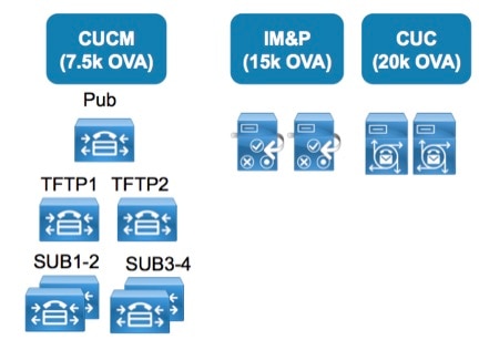
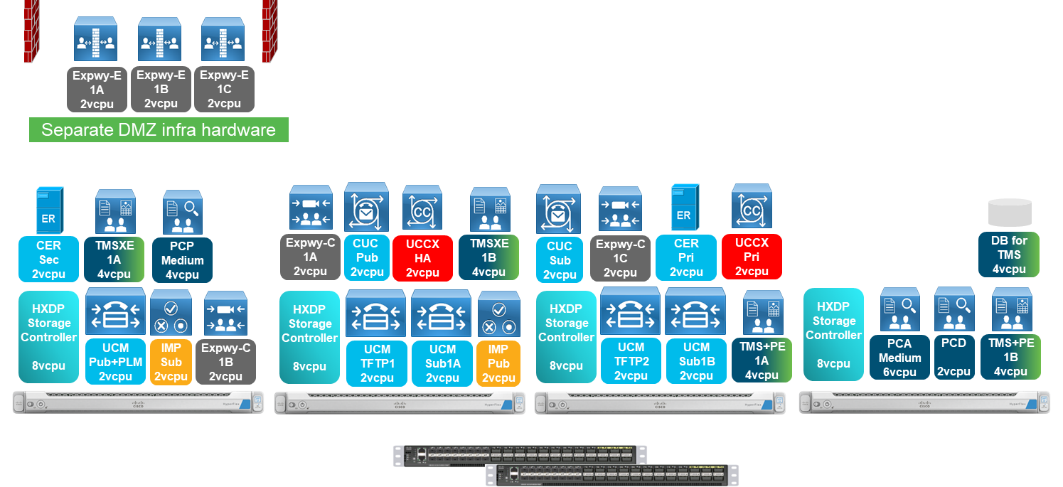
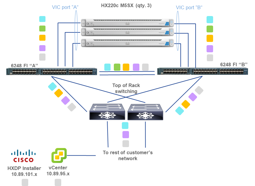
Below is an example of a Collaboration deployment running on a minimum supported infrastructure solution using HyperFlex M5 TRC. Example VM placement and VLAN/subnet/IP address planning is shown. Note this is not prescriptive guidance, only an example to assist with design and implementation planning. All IP addressing shown below is for illustrative purposes only, actuals will vary by customer deployment.
Design Example
Collaboration Design Assumptions:
Deployment Example
VLAN 109 (hx-inband-mgmt), 10.89.109.x /8
(non-routable / internal-only for HX Cluster Data)
VLAN 120 (hx-vmotion), 10.89.120.x /8
VLAN 130 (collab-apps-vnic), 10.89.200.x /8
For HX VLAN and IP address planning, including which subnets must be different, reference Network Settings and VLAN and vSwitch Requirements in the HyperFlex Getting Started Guide.
|
||||||||||||||||||||||||||||||||||||||||||||||||||||||||||||||||||||||||||||||||||||||||||||||||||||||||||||||||||||||||||||||||||||||||||||||||||||||||||||||||||||||||||||||||||||||||||||||||||||||||||||
| |
||||||||||||||||||||||||||||||||||||||||||||||||||||||||||||||||||||||||||||||||||||||||||||||||||||||||||||||||||||||||||||||||||||||||||||||||||||||||||||||||||||||||||||||||||||||||||||||||||||||||||||
| SAN/NAS |
||||||||||||||||||||||||||||||||||||||||||||||||||||||||||||||||||||||||||||||||||||||||||||||||||||||||||||||||||||||||||||||||||||||||||||||||||||||||||||||||||||||||||||||||||||||||||||||||||||||||||||
|
General Guidelines
Link Provisioning and High Availability
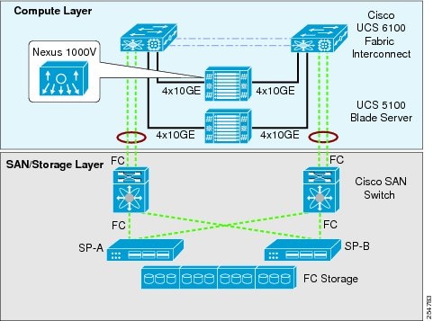
Consider the following example to determine the number of physical Fiber Channel (FC) or 10Gig Ethernet links required between your storage array (such as the EMC Clariion CX4 series or NetApp FAS 3000 Series) and SAN switch for example, Nexus or MDS Series SAN Switches), and between your SAN switch and the UCS Fabric Interconnect Switch. This example is presented to give a general idea of the design considerations involved. You should contact your storage vendor to determine the exact requirement.
Assume that the storage array has a total capacity of 28,000 Input/output Operations Per Second (IOPS). Enterprise grade SAN Storage Arrays have at least two service processors (SPs) or controllers for redundancy and load balancing. That means 14,000 IOPS per controller or service processor. With the capacity of 28,000 IOPS, and assuming a 4 KByte block size, we can calculate the throughput per storage array controller as follows:
Note: Cisco provides storage networking and switching products that are based on industry standards and that work with storage array providers such as EMC, NetApp, and so forth. Virtualized Unified Communications is supported on any storage access and storage array products that are supported by Cisco UCS and VMware. For more details on storage networking, see http://www.cisco.com/en/US/netsol/ns747/networking_solutions_sub_program_home.html.
The SAN must be compatible with the VMware HCL and compatible with the supported server model used. A SAN must also meet the following latency storage performance at all time:
There are various ways to design a SAN in order to meet the IOPS requirement for Cisco Collaboration applications (see IO Operations Per Second (IOPS) and therefore to meet the latency storage performance requirements}.
The best practices mentioned below are meant only to provide guidelines when deploying a traditional SAN. Data Center storage administrators should carefully consider these best practices and adjust them based on their specific data center network, latency, and high availability requirements.
Other SAN systems such as tiered storage that vary widely by storage vendor could also be used. In all cases, Data Center storage administrators should monitor the storage performance so that the latency storage performance requirements above are met at all time.
The storage array Hard Disk Drive (HDD) must be a Fibre Channel (FC) class HDD. These hard drives could vary in size. The current most popular HDD (spindle) sizes are:
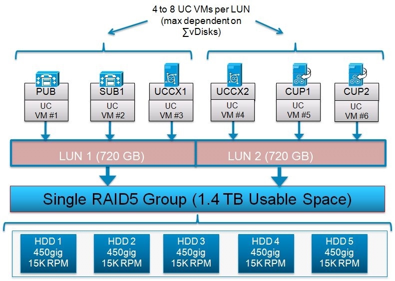
For Cisco Unified Communications virtual applications, the recommendation is to create a LUN size of between 500 GB and 1.5 TB, depending on the size of the disk and RAID group type used. Also as a recommendation, select the LUN size so that the number of Unified Communications virtual machines per LUN is between 4 and 8. Do not allocate more than eight virtual machines (VMs) per LUN or datastore. The total size of all Virtual Machines (where total size = VM disk + RAM copy) must not exceed 90% of the capacity of a datastore.
LUN filesystem type must be VMFS. Raw Device Mapping (RDM) is not supported.
The following example illustrates an example of these best practices for UC:
Next, assume two LUNs of approximately 720 GB each are created to store Unified Communications application virtual machines. For this example, between one and three LUNs per RAID group could be created based on need. Creating more than three LUNs per RAID group would violate the previously mentioned recommendation of a LUN size of between 500 GB and 1.5 TB.
A RAID group with RAID 1+0 scheme would also be valid for this example and in fact in some cases could provide better IOPS performance and high availability when compared to a RAID 5 scheme.
Below is a graphic of an example configuration following these best practices guidelines, note there are other designs possible.
|
||||||||||||||||||||||||||||||||||||||||||||||||||||||||||||||||||||||||||||||||||||||||||||||||||||||||||||||||||||||||||||||||||||||||||||||||||||||||||||||||||||||||||||||||||||||||||||||||||||||||||||
|
|
||||||||||||||||||||||||||||||||||||||||||||||||||||||||||||||||||||||||||||||||||||||||||||||||||||||||||||||||||||||||||||||||||||||||||||||||||||||||||||||||||||||||||||||||||||||||||||||||||||||||||||