المقدمة
يصف هذا المستند كيفية تنظيم التكوينات اللازمة لإعداد التوجيه بين شبكات VLAN باستخدام موجه Cisco خارجي.
المتطلبات الأساسية
المتطلبات
توصي Cisco بأن تكون لديك معرفة بالموضوع التالي:
المكونات المستخدمة
تستند المعلومات الواردة في هذا المستند إلى إصدارات البرامج التالية:
- Catalyst Switch Cisco IOS® 15.2E
- Cisco Router Cisco IOS 17.3
تم إنشاء المعلومات الواردة في هذا المستند من الأجهزة الموجودة في بيئة معملية خاصة. بدأت جميع الأجهزة المُستخدمة في هذا المستند بتكوين ممسوح (افتراضي). إذا كانت شبكتك قيد التشغيل، فتأكد من فهمك للتأثير المحتمل لأي أمر.
الاصطلاحات
للحصول على مزيد من المعلومات حول اصطلاحات المستندات، ارجع إلى اصطلاحات تلميحات Cisco التقنية.
معلومات أساسية
يصف هذا المستند التكوينات لإعداد التوجيه بين شبكات VLAN باستخدام موجه Cisco خارجي ويشرحه باستخدام نموذج التكوينات على توصيل 802.1Q؛ يتم عرض نتائج كل أمر عند تنفيذها. يمكن استخدام موجّهات سلسلة Cisco المختلفة، وأي مبدّل Catalyst switch في السيناريوهات المقدمة في هذا المستند للحصول على النتائج نفسها.
التوصيل هو وسيلة لنقل حركة المرور من عدة شبكات محلية افتراضية (VLAN) عبر ارتباط من نقطة إلى نقطة بين الجهازين. في البداية، كانت هناك طريقتان لتنفيذ توصيل Ethernet:
يتم إنشاء رابط قناة الاتصال واستخدامه لنقل حركة المرور من شبكتي VLAN أو أكثر، على سبيل المثال، VLAN1 وVLAN2 عبر رابط واحد بين مُبدّلات Catalyst و/أو موجّه Cisco.
يتم استخدام موجّه Cisco للقيام بالتوجيه ما بين شبكات VLAN بين شبكة VLAN-X وشبكة VLAN-Y. يمكن أن يكون هذا التكوين مفيدًا عندما تكون مُبدّلات سلسلة Catalyst من الطبقة 2 (L2) فقط ولا يمكنها التوجيه أو الاتصال بين شبكات VLAN.
بالنسبة لتوصيل 802.1Q، لا يتم وضع علامة على شبكة VLAN واحدة. وتُسمى شبكة VLAN هذه شبكة VLAN الأصلية. يتم استخدام شبكة VLAN الأصلية لحركة المرور غير المميزة عندما يكون المنفذ في وضع التوصيل 802.1Q. أثناء تكوين خط الاتصال 802.1Q، تذكّر أنه يجب تكوين شبكة VLAN الأصلية بالطريقة نفسها على كل جانب من جوانب ارتباط قناة الاتصال. من الأخطاء الشائعة عدم مطابقة شبكات VLAN الأصلية عند تكوين قنوات 802.1Q بين الموجّه والمُبدّل.
في نموذج التكوين هذا، تكون شبكة VLAN الأصلية هي VLAN1، بشكل افتراضي، على كل من موجّه Cisco ومبدّل Catalyst. بناء على إحتياجات الشبكة الخاصة بك، يمكنك إستخدام شبكة VLAN أصلية بخلاف شبكة VLAN الافتراضية، شبكة VLAN1. تم ذكر الأوامر في قسم التكوينات في هذا المستند حول كيفية تغيير شبكة VLAN الأصلية على هذه الأجهزة.
يمكن استخدام نماذج التكوينات المُقدمة في هذا المستند على سلسلة موجّهات Cisco المختلفة التي تدعم توصيل شبكة VLAN بمعيار 802.1Q.
ملاحظة: لا يمكن أن يكون الإصدار الأقل المعتمد هو الإصدار الموصى به بالضرورة. لتحديد أفضل إصدار صيانة لمنتج Cisco الخاص بك، ابحث عن الأخطاء المُدرجة حسب مكون المنتج في مجموعة أدوات الأخطاء.
ملاحظة: يمكن فقط لمستخدمي Cisco المسجلين الوصول إلى المستندات والأدوات والمعلومات الداخلية.
التكوين
في هذا القسم، تُقدّم لك معلومات تكوين الميزات الموضحة في هذا المستند.
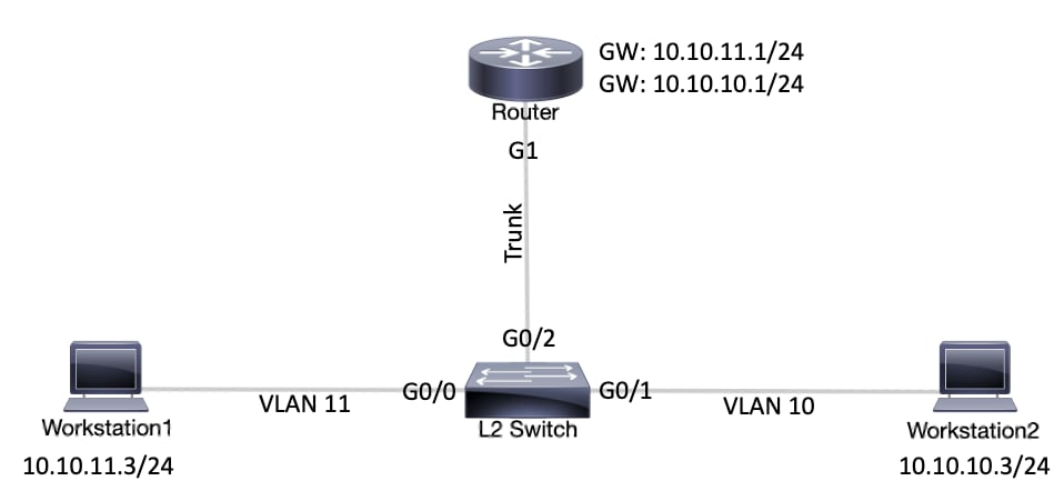
الرسم التخطيطي للشبكة
يستخدم هذا المستند إعداد الشبكة الموضح في هذا المخطط البياني.
 الرسم التخطيطي للشبكةالتكوينات
| Catalyst L2 Switch |
!-- (Optional) Set the IP address and default gateway for VLAN1 for management purposes.

L2_Switch#configure terminal
Enter configuration commands, one per line.  End with CNTL/Z.
L2_Switch(config)#interface vlan 1
L2_Switch(config-if)#ip address 10.10.0.2 255.255.255.0
L2_Switch(config-if)#no ip directed-broadcast
L2_Switch(config-if)#no ip route-cache
L2_Switch(config-if)#exit
L2_Switch(config-if)#ip default-gateway 10.10.0.1

!-- (Optional) Set the VTP Mode. In our example, we have set the mode to be transparent.
!-- Depending on your network, set the VTP Mode accordingly.

L2_Switch(config)#vtp mode transparent
Setting device to VTP Transparent mode for VLANS.
L2_Switch(config)#

!-- Adding VLAN10 and VLAN11.

L2_Switch(config)#vlan 10-11
L2_Switch(config-vlan)#exit
L2_Switch(config)#

!-- Enable trunking on the interface GigabitEthernet 0/2.
!-- Enter the trunking encapsulation as dot1q.

L2_Switch(config)#interface gigabitEthernet 0/2
L2_Switch(config-if)#switchport trunk encapsulation dot1q
L2_Switch(config-if)#switchport mode trunk

!-- In case of dot1q, you need to make sure that the native VLAN matches across the link.
!-- On Catalyst Switches, by default, the native VLAN is 1.
!-- It is very important that you change the native VLAN on the router accordingly.

!-- The following set of commands can place on the interfaces connecting to the workstations.

L2_Switch(config)#interface gigabitEthernet 0/0
L2_Switch(config-if)#switchport mode access
L2_Switch(config-if)#switchport access vlan 11
L2_Switch(config-if)#exit

L2_Switch(config)#interface gigabitEthernet 0/1
L2_Switch(config-if)#switchport mode access
L2_Switch(config-if)#switchport access vlan 10
L2_Switch(config-if)#exit

!-- Remember to save the configuration.

L2_Switch#write memory
Building configuration...
|
| الموجّه |
|
ملاحظة: تظهر لقطات الشاشة التالية الأوامر التي تم إدخالها على موجه Cisco. تتم إضافة التعليقات بين الأوامر بخط مائل لشرح أوامر وخطوات معينة.
Router#configure terminal
Enter configuration commands, one per line. End with CNTL/Z.

!-- Select GigabitEthernet 1 for the trunk configuration.
!-- No Layer 3 (L3) configuration is done here.

Router(config)#interface GigabitEthernet 1
Router(config-if)#no shut
Router(config-if)#exit

!-- Enable dot1q on the sub-interface one for each VLAN.
!-- Configure L3 information on the sub-interface for each gateway.

Router(config)#interface gigabitEthernet 1.10
Router(config-subif)#encapsulation dot1Q 10
Router(config-subif)#ip address 10.10.10.1 255.255.255.0
Router(config-subif)#exit

Router(config)#interface gigabitEthernet 1.11
Router(config-subif)#encapsulation dot1Q 11
Router(config-subif)#ip address 10.10.11.1 255.255.255.0
Router(config-subif)#exit

!-- (Optional) For the management VLAN 1 make sure that the native VLAN matches across the link.
!-- On the switch, by default, the native VLAN is 1.
!-- On the router, configure VLAN1 as the native VLAN.

Router(config)#interface gigabitEthernet 1.1
Router(config-subif)#encapsulation dot1Q 1 native
Router(config-subif)#ip address 10.10.0.1 255.255.255.0
Router(config-subif)#end

!-- Remember to save the configuration.

Router#write memory
Building configuration...
[OK]
Router#
ملاحظة: لتنفيذ هذا الإعداد بنجاح، ولإختبار الاتصال بنجاح بين محطة العمل 1 ومحطة العمل 2، يلزمك التأكد من إعداد البوابات الافتراضية على محطات العمل بشكل صحيح. بالنسبة لمحطة العمل 1، يجب أن تكون العبّارة الافتراضية 10.10.11.1 وبالنسبة لمحطة العمل 2، يجب أن تكون العبّارة الافتراضية 10.10.10.1.
|
أوامر مفيدة
يساعدك هذا القسم على التأكد من أن التكوين الخاص بك يعمل على النحو المتوقع.
في مبدّل Catalyst، يمكنك استخدام الأوامر التالية للمساعدة في التحقق:
على موجّه Cisco، استخدم الأوامر التالية:
-
show ip route
-
show interface
نموذج إخراج الأوامر
Catalyst Switch
يتم استخدام الأمر التالي للتحقق من الحالة الإدارية والتشغيلية للمنفذ. كما أنه يتم استخدامه للتأكد من تطابق شبكة VLAN الأصلية على كلا جانبي قناة الاتصال. يتم استخدام شبكة VLAN الأصلية لحركة المرور غير المميزة عندما يكون المنفذ في وضع التوصيل 802.1Q.
بالنسبة إلى توصيل 802.1Q، يعرض أمر الإخراج:
L2_Switch#show interfaces gigabitEthernet 0/2 switchport
Name: Gi0/2
Switchport: Enabled
Administrative Mode: trunk
Operational Mode: trunk
Administrative Trunking Encapsulation: dot1q
Operational Trunking Encapsulation: dot1q
Negotiation of Trunking: On
Access Mode VLAN: 1 (default)
Trunking Native Mode VLAN: 1 (default)
Administrative Native VLAN tagging: enabled
Voice VLAN: none
Administrative private-vlan host-association: none
Administrative private-vlan mapping: none
Administrative private-vlan trunk native VLAN: none
Administrative private-vlan trunk Native VLAN tagging: enabled
Administrative private-vlan trunk encapsulation: dot1q
Administrative private-vlan trunk normal VLANs: none
Administrative private-vlan trunk associations: none
Administrative private-vlan trunk mappings: none
Operational private-vlan: none
Trunking VLANs Enabled: ALL
Pruning VLANs Enabled: 2-1001
Capture Mode Disabled
Capture VLANs Allowed: ALL

Protected: false
Appliance trust: none
يتم استخدام الأمر التالي للتحقق من أن الواجهات (المنافذ) تنتمي إلى شبكة VLAN الصحيحة. في هذا المثال، تنتمي الواجهة gi0/1 إلى شبكة VLAN10 وينتمي gi0/0 إلى شبكة VLAN11. أما الباقي فهم أعضاء في شبكة VLAN1.
L2_Switch#show vlan brief

VLAN Name                             Status    Ports
---- -------------------------------- --------- -------------------------------
1    default                          active    Gi0/3
10   VLAN0010                         active    Gi0/1
11   VLAN0011                         active    Gi0/0
1002 fddi-default                     act/unsup
1003 token-ring-default               act/unsup
1004 fddinet-default                  act/unsup
1005 trnet-default                    act/unsup
L2_Switch#
يتم استخدام الأمر التالي للتحقق من تكوين بروتوكول توصيل شبكة VLAN على المُبدّل. في هذا المثال، يتم استخدام الوضع الشفاف. يعتمد وضع VTP الصحيح على هيكل شبكتك.
L2_Switch#show vtp status
VTP Version capable             : 1 to 3
VTP version running             : 1
VTP Domain Name                 :
VTP Pruning Mode                : Disabled
VTP Traps Generation            : Disabled
Device ID                       : 5254.0000.8000
Configuration last modified by 0.0.0.0 at 3-1-24 15:21:18

Feature VLAN:
--------------
VTP Operating Mode                : Transparent
Maximum VLANs supported locally   : 1005
Number of existing VLANs          : 7
Configuration Revision            : 0
MD5 digest                        : 0x9F 0x7D 0x8D 0x10 0xB1 0x22 0x2F 0xE7
                                    0x29 0x77 0x42 0xA7 0x95 0xE7 0x68 0x1C
موجّه Cisco
يخبر الأمر التالي بمعلومات توجيه L3 حول الواجهات الفرعية التي تم تكوينها على الموجّه.
Router#show ip route
Codes: L - local, C - connected, S - static, R - RIP, M - mobile, B - BGP
       D - EIGRP, EX - EIGRP external, O - OSPF, IA - OSPF inter area
       N1 - OSPF NSSA external type 1, N2 - OSPF NSSA external type 2
       E1 - OSPF external type 1, E2 - OSPF external type 2, m - OMP
       n - NAT, Ni - NAT inside, No - NAT outside, Nd - NAT DIA
       i - IS-IS, su - IS-IS summary, L1 - IS-IS level-1, L2 - IS-IS level-2
       ia - IS-IS inter area, * - candidate default, U - per-user static route
       H - NHRP, G - NHRP registered, g - NHRP registration summary
       o - ODR, P - periodic downloaded static route, l - LISP
       a - application route
       + - replicated route, % - next hop override, p - overrides from PfR
       & - replicated local route overrides by connected

Gateway of last resort is not set

      10.0.0.0/8 is variably subnetted, 6 subnets, 2 masks
C        10.10.0.0/24 is directly connected, GigabitEthernet1.1
L        10.10.0.1/32 is directly connected, GigabitEthernet1.1
C        10.10.10.0/24 is directly connected, GigabitEthernet1.10
L        10.10.10.1/32 is directly connected, GigabitEthernet1.10
C        10.10.11.0/24 is directly connected, GigabitEthernet1.11
L        10.10.11.1/32 is directly connected, GigabitEthernet1.11
يتم استخدام الأمر التالي للتحقق من الحالة الإدارية والتشغيلية للواجهة. بالنسبة لحالة واجهة الموجّه، يعرض أمر الإخراج:
Router#show interfaces
GigabitEthernet1 is up, line protocol is up
  Hardware is CSR vNIC, address is 5254.0000.004d (bia 5254.0000.004d)
  MTU 1500 bytes, BW 1000000 Kbit/sec, DLY 10 usec,
     reliability 255/255, txload 1/255, rxload 1/255
  Encapsulation ARPA, loopback not set
  Keepalive set (10 sec)
  Full Duplex, 1000Mbps, link type is auto, media type is Virtual
  output flow-control is unsupported, input flow-control is unsupported
  ARP type: ARPA, ARP Timeout 04:00:00
  Last input 00:00:00, output 00:14:10, output hang never
  Last clearing of "show interface" counters never
  Input queue: 0/375/0/0 (size/max/drops/flushes); Total output drops: 0
  Queueing strategy: fifo
  Output queue: 0/40 (size/max)
  5 minute input rate 0 bits/sec, 0 packets/sec
  5 minute output rate 0 bits/sec, 0 packets/sec
     5338 packets input, 361563 bytes, 0 no buffer
     Received 0 broadcasts (0 IP multicasts)
     0 runts, 0 giants, 0 throttles
     0 input errors, 0 CRC, 0 frame, 0 overrun, 0 ignored
     0 watchdog, 0 multicast, 0 pause input
     13 packets output, 1248 bytes, 0 underruns
     Output 0 broadcasts (0 IP multicasts)
     0 output errors, 0 collisions, 2 interface resets
     57 unknown protocol drops
     0 babbles, 0 late collision, 0 deferred
     1 lost carrier, 0 no carrier, 0 pause output
     0 output buffer failures, 0 output buffers swapped out
GigabitEthernet1.1 is up, line protocol is up
  Hardware is CSR vNIC, address is 5254.0000.004d (bia 5254.0000.004d)
  Internet address is 10.10.0.1/24
  MTU 1500 bytes, BW 1000000 Kbit/sec, DLY 10 usec,
     reliability 255/255, txload 1/255, rxload 1/255
  Encapsulation 802.1Q Virtual LAN, Vlan ID  1.
  ARP type: ARPA, ARP Timeout 04:00:00
  Keepalive set (10 sec)
  Last clearing of "show interface" counters never
GigabitEthernet1.10 is up, line protocol is up
  Hardware is CSR vNIC, address is 5254.0000.004d (bia 5254.0000.004d)
  Internet address is 10.10.10.1/24
  MTU 1500 bytes, BW 1000000 Kbit/sec, DLY 10 usec,
     reliability 255/255, txload 1/255, rxload 1/255
  Encapsulation 802.1Q Virtual LAN, Vlan ID  10.
  ARP type: ARPA, ARP Timeout 04:00:00
  Keepalive set (10 sec)
  Last clearing of "show interface" counters never
GigabitEthernet1.11 is up, line protocol is up
  Hardware is CSR vNIC, address is 5254.0000.004d (bia 5254.0000.004d)
  Internet address is 10.10.11.1/24
  MTU 1500 bytes, BW 1000000 Kbit/sec, DLY 10 usec,
     reliability 255/255, txload 1/255, rxload 1/255
  Encapsulation 802.1Q Virtual LAN, Vlan ID  11.
  ARP type: ARPA, ARP Timeout 04:00:00
  Keepalive set (10 sec)
  Last clearing of "show interface" counters never
GigabitEthernet2 is administratively down, line protocol is down
  Hardware is CSR vNIC, address is 5254.0000.004e (bia 5254.0000.004e)
  MTU 1500 bytes, BW 1000000 Kbit/sec, DLY 10 usec,
     reliability 255/255, txload 1/255, rxload 1/255
  Encapsulation ARPA, loopback not set
  Keepalive set (10 sec)
  Full Duplex, 1000Mbps, link type is auto, media type is Virtual
  output flow-control is unsupported, input flow-control is unsupported
  ARP type: ARPA, ARP Timeout 04:00:00
  Last input never, output never, output hang never
  Last clearing of "show interface" counters never
  Input queue: 0/375/0/0 (size/max/drops/flushes); Total output drops: 0
  Queueing strategy: fifo
معلومات ذات صلة
 التعليقات