-
Cisco IP Phone Model 7902G, 7905G, and 7912G Administration Guide for Cisco CallManager Release 3.3 and later
-
Index
-
Preface
-
An Overview of the Cisco IP Phone
-
Preparing to Install the Cisco IP Phone on Your Network
-
Installing the Cisco IP Phone
-
Configuring Network Settings on the Cisco IP Phone
-
Configuring Users and Features
-
Troubleshooting the Cisco IP Phone
-
Additional Configuration Methods, Parameters, and Procedures
-
Technical Specifications
-
 Feedback
Table Of Contents
Cisco CallManager Configuration
Connecting the Cisco IP Phone to the Network
Mounting the Phone to the Wall
Verifying the Phone Startup Process
Configuring Startup Network Settings
Installing the Cisco IP Phone
These topics help you install the Cisco IP Phone on an IP telephony network:
•
Connecting the Cisco IP Phone to the Network
•
•
•
Note
Before You Begin
Before installing the Cisco IP Phone, review the requirements in these sections:
•
Network Requirements
For the Cisco IP Phone to successfully operate as a Cisco IP Phone endpoint in your network, your network must meet the following requirements:
•
–
–
•
Cisco CallManager Configuration
The Cisco IP Phone requires Cisco CallManager to handle call processing. Refer to the Cisco CallManager Administration Guide or context-sensitive help in the Cisco CallManager application to ensure that Cisco CallManager is set up properly to manage the phone and to properly route and process calls.
If you plan to use auto-registration, verify that it is enabled and properly configured in Cisco CallManager before connecting any Cisco IP Phone to the network. See the "Using Auto-Registration" section on page 2-12 for details.
You must use Cisco CallManager to configure and assign telephony features to the Cisco IP Phones. See the "Configuring Telephony Features Using Cisco CallManager Administration" section on page 5-2 for details.
In Cisco CallManager, you can add users to the database and associate them with specific phones. By doing this, users gain access to web pages that allow them to configure phone options such as call forwarding and speed dialing. See the "Adding Users to Cisco CallManager" section on page 5-7 for details.
Note
Safety
Review the following warnings before installing the Cisco IP Phone. To see translations of these warnings, refer to the Regulatory Compliance and Safety Information for the Cisco IP Phone 7900 Series document that accompanied this device.
Warning
Warning
Warning
Warning
Warning
The following warnings apply when you use an external power supply.
Warning
Warning
Warning
Connecting the Cisco IP Phone to the Network
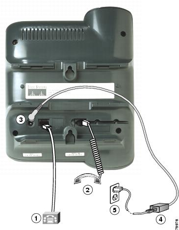
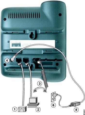
You must connect the Cisco IP Phone to the network and to a power source before using it. See Figure 3-1 and Figure 3-2 for graphical overviews of the procedures that follow.
To install a Cisco IP Phone, perform these steps.
Procedure
Step 1
See the "Connecting to the Network" section on page 2-8 for guidelines. Each Cisco IP Phone ships with one Ethernet cable in the box.
Step 2
Step 3
See the "Connecting to the Network" section on page 2-8 for guidelines.
Note
Step 4
See the "Providing Power to the Cisco IP Phone" section on page 2-9.
Figure 3-1 Cisco IP Phone Models 7902G/7905G Cable Connections
Figure 3-2 Cisco IP Phone Model 7912G Cable Connections
Mounting the Phone to the Wall
You can mount the Cisco IP Phone on the wall by removing the footstand and using the mounting bracket on the back of the phone, or you can use special brackets available in a Cisco IP Phone wall mount kit. (A wall mount kit must be ordered separately from the phone.) If you attach the Cisco IP Phone to the wall using the standard footstand and not the wall mount kit, you need to supply the following tools and parts:
•
•
Use the following procedure to mount the phone on the wall using its mounting bracket.
Before You Begin
To ensure that the handset attaches securely to a wall-mounted phone, remove the handset wall hook from the handset rest, rotate the hook 180 degrees, and reinsert the hook. Turning the hook exposes a lip on which the handset catches when the phone is vertical. For an illustrated procedure, see Installing the Wall Mount Kit for the Cisco IP Phone.
Procedure
Step 1
Step 2
a.
b.
c.
d.
Step 3
The keyholes fit standard phone jack mounts.
Step 4
Verifying the Phone Startup Process
After the Cisco IP Phone has power connected to it, the phone begins its startup process by cycling through the following steps.
Cisco IP Phone 7902G
The phone uses a combination of the three LEDs (handset, Hold, and Menu buttons) to indicate the phone startup process. After several minutes, startup is complete and your phone is ready to use. When all of the LEDs are off, you will hear a dial tone when you lift the handset. If the phone does not start up successfully, see "Checking the Light Indicators on a Cisco IP Phone 7902G" section on page 6-11.
Cisco IP Phone Models 7905G/7912G
1.
2.
3.
•
•
•
•
•
4.
•
•
•
If the phone successfully passes through these stages, it has started up properly. Otherwise, see to the "Resolving Startup Problems" section on page 6-12.
Configuring Startup Network Settings
If you are not using DHCP in your network, you must configure these network settings on the Cisco IP Phone after installing the phone on the network:
•
•
•
•
•
•
Collect this information and follow the procedures defined in Chapter 4, "Configuring Network Settings on the Cisco IP Phone."