-
Troubleshooting Guide for Cisco CallManager, Release 3.3(3)
-
Index
-
Preface
-
Troubleshooting Overview
-
Troubleshooting Tools
-
Installation, Backup, and Restore Issues
-
Cisco CallManager System Issues
-
Directory Issues
-
Device Issues
-
Dial Plans and Routing Issues
-
Cisco CallManager Services Issues
-
Voice Messaging Issues
-
Opening a Case With TAC
-
Case Study: Troubleshooting Intracluster Phone Calls
-
Case Study: Troubleshooting Cisco IP Phone-to-Cisco IOS Gateway Calls
-
Case Study: Troubleshooting Intercluster Phone Calls
-
 Feedback
Table Of Contents
Correcting Audio Problems from the Cisco IP Phone
Intercluster Trunks or H.225 Trunks
Cisco CallManager Locks the B-Channel and Sends Restart
B-Channel Remains Locked When Restart_Ack Does Not Contain Channel IE
Device Issues
This chapter addresses the following common problems that you may experience with Cisco IP Phones, gateways, and related devices.
•
B-Channel Remains Locked When Restart_Ack Does Not Contain Channel IE
Voice Quality
You may experience voice quality issues including lost or distorted audio signal during phone calls.
Common problems include audio breaks (like broken words) or the presence of odd noises and audio distortion, such as echo, and watery or robotic voice quality. One-way audio, that is, a conversation between two people where only one person can hear anything, does not actually represent a voice quality issue, but this section covers this issue.
You may experience audio problems with one or more of the following items:
•
•
•
This section covers the following common voice quality problems:
•
•
Lost or Distorted Audio
Symptom
One of the most common problems that you may encounter involves broken audio signal (often described as garbled speech or lost syllables within a word or sentence). Two common causes for this exist: packet loss and/or jitter. Packet loss means that audio packets do not arrive at their destination because they were dropped or arrived too late to be useful. Jitter describes the variation in the arrival times of packets. In the ideal situation, all Voice over IP (VoIP) packets would arrive exactly at a rate of 1 every 20 microseconds (ms). Notice that this is not the it takes for a packet to get from point A to point B but is simply the variation in packet arrival times.
Probable Cause
Many sources of variable delay exist in a network. You can control some of these but not others. You cannot entirely eliminate variable delay in a packetized voice network. Digital Signal Processors (DSP) on phones and other voice-capable devices by design buffer some of the audio in anticipation of variable delay. This dejittering occurs only when the audio packet has reached its destination and is now ready to be put into a conventional audio stream.
The Cisco IP Phone 7960 can buffer as much as 1 second of voice samples. The jitter buffer is adaptive, meaning if a burst of packets is received, the Cisco IP Phone 7960 can play them out in an attempt to control the jitter. The network administrator needs to minimize the variation between packet arrival times by applying quality-of-service (QoS) and other measures in advance (especially if calls cross a WAN).
Corrective Action
Procedure
Step 1
Step 2
Disable the service in Cisco CallManager Administration, choose Service > Service Parameters. From there, choose the server and the Cisco CallManager service as shown in Figure 6-1.
Figure 6-1 Cisco CallManager Administration Service Menu
Step 3
Step 4
Remember that delay by itself will not cause clipping, only variable delay. Notice in the table below, which represents a perfect trace, the arrival times between the audio packets (which will have an RTP header) that will be 20 ms. In a poor quality call (such as a call with a lot of jitter), the arrival times would vary greatly.
The following table illustrates a perfect trace.
Placing the packet analyzer into various points in the network will help narrow the number of places from which the delay is coming from. If no analyzer is available, you will need to use other methods. Examine interface statistics of each device in the path of the audio.
Diagnostic Call Detail Records (CDR) specifies another tool for tracking calls with poor voice quality. Refer to the Cisco CallManager Serviceability Administration Guide for more information about CDRs.
Correcting Audio Problems from the Cisco IP Phone
Symptom
Audio problems occurs while a call is in progress.
Probable Cause
Devices, where a higher speed interface feeds into a lower speed interface, provide the most common sources for delay and packet loss. For example, a router may have a 100 Megabyte (MB) fast Ethernet interface connected to the LAN and a slow frame-relay interface, connected to the WAN. If the poor audio quality occurs only when communicating to the remote site, the most likely causes of the problem include
•
•
•
•
On the LAN, the most common problems represent physical-level errors (such as CRC errors) that are caused by faulty cables, interfaces, or by incorrectly configured devices (such as a port speed or duplex mismatch). Make sure that the traffic is not crossing any shared-media device, such as a hub.
Corrective Action
The Cisco IP Phone 7960 provides another tool for diagnosing possible audio problems.
Procedure
Step 1
Note
Step 2
Diagnosing Crackling Sounds
Step 3
Checking Your Loads
Step 4
Verification
Procedure
Step 1
Step 2
Step 3
Echo
Symptom
Echo occurs when the speech energy being generated and transmitted down the primary signal path is coupled into the receive path from the far end. The speaker then hears his or her own voice, delayed by the total echo path delay time.
Voice can reflect back. This can happen but goes unnoticed in a traditional voice network because the delay is so low. To the user, it sounds more like a side-tone than an echo. In a VoIP network, it will always be noticeable because packetization and compression contribute to the delay.
Probable Cause
Remember that the cause of the echo is always with analog components and wiring. For instance, IP packets cannot simply turn around and go back to the source at a lower audio level or on digital T1/E1 circuits. The only exception may occur if one party is using a speakerphone that has the volume set too high or other situations where an audio loop is created.
Corrective Action
Procedure
Step 1
Testing the Gateway
Step 2
Additionally, you can adjust the receive level, so any reflected audio is reduced even further. Remember to make small adjustments at a time. Too much attenuation of the signal will make the audio impossible to hear on both sides.
Step 3
Keeping an Echo Log
Step 4
Record the time of the problem, the source phone number, and the number called. Gateways have a fixed time of 16 ms of echo cancellation.
If the delay in the reflected audio is longer than this, the echo cancellor cannot work properly. This should not be an issue for local calls, and long distance calls should have external echo cancellers built into the network at the Central Office. This fact provides one of the reasons why it is important to note the external phone number of a call that experiences echo.
Checking Your Loads
Step 5
One-Way Audio or No Audio
Symptom
When one person cannot hear another person during a call, one-way audio exists.
Probable Cause
An improperly configured Cisco IOS Gateway, a firewall, or a routing or default gateway problem, among other things can cause this problem.
Corrective Action
Procedure
Step 1
You can also press the i button twice quickly on a Cisco IP Phone 7960 during an active call to view details about transmitted and received packets.
Checking the MTP
Step 2
You can use the MTP device, as well as Conference Bridge and transcoder features, to bridge two or more audio streams. If the MTP, Conference Bridge, or transcoder is not working properly, you may experience one-way audio or audio loss. Shut down MTP to find out whether MTP is causing the problem.
Testing Cisco CallManager Configuration
Step 3
If a call consistently has one-way audio, use a PC that is configured on the same subnet as the phone and has the same default gateway and try to ping the destination Cisco IP Phone.
Step 4
Step 5
Ensure that IP routing is enabled (look at the configuration to make sure that no IP routing is not found near the beginning of the configuration).
Checking RTP Header Compression
Step 6
Note
Codec and Region Mismatches
If a user gets a reorder tone (busy signal) when going off hook, it could be the result of codec disagreement between regions. Verify that both call ends support at least one common codec (for example, G.711). If they do not, you will need to use transcoders.
A region specifies the range of supported codecs that can be used with each of the other regions. Every device belongs to a region.
Note
For example, Region1<->Region2 = G.711, means that a call between a device in Region1 and a device in Region2 can use G.711 or any other supported codec that requires the same or less bandwidth as G.711 (any supported codecs within G.711, G.729, G.723, and so on).
Note
Cisco IP Phone 7960—G.711A-law/µ-law, G.729AnnexB
Cisco IP Phone SP12 series and VIP 30—G.711a-law/mu-law, G.723.1
Cisco Access Gateway DE30 and DT-24+—G.711a-law/mu-law, G.723.1
Location and Bandwidth
If a user gets a reorder tone after dialing a number, this could happen because the Cisco CallManager bandwidth allocation for the location of one of the call end devices has been exceeded. Cisco CallManager checks for 24k available bandwidth for each device before making a call. If less than 24k bandwidth is available, Cisco CallManager will not set up the call, and the user receives a reorder tone.
12:42:09.017 Cisco CallManager|Locations:	Orig=1 BW=12	Dest=0 BW=-1	(-1
implies infinite bw available)
12:42:09.017 Cisco CallManager|StationD - stationOutputCallState
tcpHandle=0x4f1ad98
12:42:09.017 Cisco CallManager|StationD - stationOutputCallInfo
CallingPartyName=,  CallingParty=5003, CalledPartyName=,
CalledParty=5005, tcpHandle=0x4f1ad98
12:42:09.017 Cisco CallManager|StationD - stationOutputStartTone:
37=ReorderTone tcpHandle=0x4f1ad98
Once the call is established, the Cisco CallManager will subtract bandwidth from the locations, depending on the codec used in that call. If the call is using G.711, Cisco CallManager will subtract 80k; if the call is using G.723, Cisco CallManager will subtract 24k; if the call is using G.729, Cisco CallManager will subtract 24k.
Phone Resets
Symptom
Phone resets.
Probable Cause
Phones will power cycle or reset for two reasons:
•
•
Corrective Action
Procedure
Step 1
Step 2
Step 3
Step 4
Step 5
•
•
Step 6
Dropped Calls
Symptom
Premature termination of dropped calls.
Probable Cause
Premature termination of dropped calls can be the result of a phone or gateway resetting (see Phone Resets) or a circuit problem, such as incorrect PRI configuration.
Corrective Action
Procedure
Step 1
Step 2
You will see one Warning and one Error message for each phone that resets. This indicates that the phone cannot keep its TCP connection to the Cisco CallManager alive, so the Cisco CallManager resets the connection. This may occur because a phone was turned off or a problem may exist in the network. If this is an intermittent problem, you may find it useful to use Microsoft Performance to record phone registrations.
Step 3
Step 4
http://www.cisco.com/univercd/cc/td/doc/product/software/ios113ed/dbook/disdn.htm.
Step 5
Gateway Reorder Tone
Symptom
Reorder tone occurs.
Probable Cause
Users placing a call through the gateway might get a reorder tone if they are attempting to make a restricted call or to call a number that has been blocked. A reorder tone may occur if the dialed number is out of service or if the PSTN has an equipment or service problem.
Check to be sure that the device giving the reorder tone has registered. Also, check your dial plan configuration to ensure that the call can be successfully routed.
Corrective Action
The following procedure shows the steps for troubleshooting reorder tones through gateways.
Procedure
Step 1
Step 2
Step 3
Step 4
Gateway Registration Failure
This section describes two similar but different categories of gateways. The Cisco Access AS-X, AT-X and Cisco Access DT-24+ and DE-30+ belong to one category. These gateways identify stand-alone units that are not directly connected to a Network Management Processor (NMP). The second category includes the Analog Access WS-X6624 and Digital Access WS-X6608. These gateways, as blades installed in a Catalyst 6000 chassis, provide direct connectivity to the NMP for control and statusing.
Symptom
A registration problem represents one of the most common issues that are encountered with gateways on a Cisco CallManager.
Probable Cause
Registration can fail for a variety of reasons.
Corrective Action
Procedure
Step 1
If this LED is not blinking at all, or blinking very rapidly, the gateway software is not running. Normally, this results in an automatic reset of the gateway. Also, it is normal for the gateway to reset itself if it cannot complete the registration process after about 2 to 3 minutes. So, you may happen to look at the heartbeat LED while the device is resetting, but if the normal blinking pattern does not appear in 10 to 15 seconds, the gateway has suffered a serious failure.
On the Cisco Access Analog gateways, find the green heartbeat LED on the far right of the front panel. On the Cisco Access Digital gateways, find the red LED on the far left on the top edge of the card. On the Cisco Analog Access WS-X6624, a green LED appears inside the blade (not visible from the front panel) on the far right card edge near the front. Finally, on the Digital Access WS-X6608, a separate heartbeat LED exists for each of the 8 spans on the blade. Eight red LEDs appear across the card (not visible from the front panel) about two thirds of the way towards the back.
Step 2
Step 3
Step 4
Step 5
Step 6
Step 7
The IP address uses this format:
127.1.module.portFor example, for port 1 on module 7, you would enter
Console (enable) ping 127.1.7.1127.1.7.1 is aliveStep 8
Step 9
Step 10
tracy_start mod port
In this example, the WS-X6624 represents module 7, and it has only a single 860 processor, so it is port 1. The command to issue is tracy_start 7 1.
The following output actually comes from the 860-console port on the gateway board itself; however, the output of the tracy command represents nothing more than a remote copy of the 860-console port.
| || || | | | | || | | | | | | | | || | | | | | |:.:| | | | | | |:..C i s c o S y s t e m sCAT6K Analog Gateway (ELVIS)APP Version : A0020300, DSP Version : A0030300, Built Jun 1 2000 16:33:01ELVIS>> 00:00:00.020 (XA) MAC Addr : 00-10-7B-00-13-DE00:00:00.050 NMPTask:got message from XA Task00:00:00.050 (NMP) Open TCP Connection ip:7f01010100:00:00.050 NMPTask:Send Module Slot Info00:00:00.060 NMPTask:get DIAGCMD00:00:00.160 (DSP) Test Begin -> Mask<0x00FFFFFF>00:00:01.260 (DSP) Test Complete -> Results<0x00FFFFFF/0x00FFFFFF>00:00:01.260 NMPTask:get VLANCONFIG00:00:02.870 (CFG) Starting DHCP00:00:02.870 (CFG) Booting DHCP for dynamic configuration.00:00:06.570 (CFG) DHCP Request or Discovery Sent, DHCPState = INIT_REBOOT00:00:06.570 (CFG) DHCP Server Response Processed, DHCPState = INIT_REBOOT00:00:06.780 (CFG) IP Configuration Change! Restarting now...00:00:10.480 (CFG) DHCP Request or Discovery Sent, DHCPState = INIT00:00:14:480 (CFG) DHCP Timeout Waiting on Server, DHCPState = INIT00:00:22:480 (CFG) DHCP Timeout Waiting on Server, DHCPState = INIT00:00:38:480 (CFG) DHCP Timeout Waiting on Server, DHCPState = INITIf this timeout message continues to scroll by, a problem exists with contacting the DHCP server.
Step 11
You will find this information in the information that you retrieved by using the show port command.
Step 12
Step 13
tracy_close mod port
tracy_start mod port
Step 14
Step 15
Once DHCP is working correctly, the gateway will have an IP address that allows the use of the tracy debugging utility. This utility includes a built in feature of the NMP command set for the Catalyst gateways and is available as a helper application that runs on Windows 98/NT/2000 for the standalone gateways.
Step 16
Step 17
If Option 66 provides the DNS_NAME of the TFTP server, then the DNS server(s) IP address(es) must have been specified by DHCP, and the name entered in Option 66 must resolve to the correct TFTP server IP address. The NMP could configure a Catalyst gateway could be configured by the NMP to disable DHCP, and the NMP operator must then manually enter all configuration parameters at the console, including the TFTP server address.
Additionally, the gateways will always attempt to resolve the name CiscoCM1 via DNS. If successful, the CiscoCM1 IP address will take precedence over anything that the DHCP server or NMP tells it for the TFTP server address, even if the NMP has DHCP disabled.
Step 18
TaskID: 0Cmd: show tlLook for a line with config or CFG and use the corresponding number as the taskID for the next line, such as, for the Cisco Access Digital gateway. In the examples that follow, bolded lines of text make it easier for you to see the messages being explained. In the actual display output, text does not appear bolded. The examples come from an WS-X6624 model; the command to dump the DHCP information is
TaskID: 6Cmd: show dhcpStep 19
Step 20
00:09:05.620 (CFG) Requesting SAA00107B0013DE.cnf File From TFTP
Server
00:09:18.620 (CFG) TFTP Error: Timeout Awaiting Server Response for .cnf File!The gateway attempts to connect to the same IP address as the TFTP server if it does not get a configuration file. This works fine unless you are in a clustered environment in which the gateway needs to receive its list of redundant Cisco CallManagers.
Step 21
Step 22
Another common problem occurs if the gateway is not configured correctly on the Cisco CallManager. A typical error involves entering an incorrect MAC address for the gateway. If this is the case, for a Catalyst 6000 gateway, you will probably get the following messages on the NMP console every 2 minutes:
2000 Apr 14 19:24:08 %SYS-4-MODHPRESET:Host process (860) 7/1 got
reset asynchronously
2000 Apr 14 19:26:05 %SYS-4-MODHPRESET:Host process (860) 7/1 got reset asynchronously2000 Apr 14 19:28:02 %SYS-4-MODHPRESET:Host process (860) 7/1 got reset asynchronouslyThe following example shows what the tracy output would look like if the gateway is not in the Cisco CallManager database:
00:00:01.670 (CFG) Booting DHCP for dynamic configuration.00:00:05.370 (CFG) DHCP Request or Discovery Sent, DHCPState = INIT_REBOOT00:00:05.370 (CFG) DHCP Server Response Processed, DHCPState = BOUND00:00:05.370 (CFG) Requesting DNS Resolution of CiscoCM100:00:05.370 (CFG) DNS Error on Resolving TFTP Server Name.00:00:05.370 (CFG) TFTP Server IP Set by DHCP Option 150 = 10.123.9.200:00:05.370 (CFG) Requesting SAA00107B0013DE.cnf File From TFTP Server00:00:05.370 (CFG) TFTP Error: .cnf File Not Found!00:00:05.370 (CFG) Requesting SAADefault.cnf File From TFTP Server00:00:05.380 (CFG) .cnf File Received and Parsed Successfully.00:00:05.380 (CFG) Updating Configuration ROM...00:00:05.610 GMSG: GWEvent = CFG_DONE --> GWState = SrchActive00:00:05.610 GMSG: CCM#0 CPEvent = CONNECT_REQ --> CPState = AttemptingSocket00:00:05.610 GMSG: Attempting TCP socket with CCM 10.123.9.200:00:05.610 GMSG: CCM#0 CPEvent = SOCKET_ACK --> CPState = BackupCCM00:00:05.610 GMSG: GWEvent = SOCKET_ACK --> GWState = RegActive00:00:05.610 GMSG: CCM#0 CPEvent = REGISTER_REQ --> CPState = SentRegister00:00:05.680 GMSG: CCM#0 CPEvent = CLOSED --> CPState = NoTCPSocket00:00:05.680 GMSG: GWEvent = DISCONNECT --> GWState = Rollover00:00:20.600 GMSG: GWEvent = TIMEOUT --> GWState = SrchActive00:00:20.600 GMSG: CCM#0 CPEvent = CONNECT_REQ --> CPState = AttemptingSocket00:00:20.600 GMSG: Attempting TCP socket with CCM 10.123.9.200:00:20.600 GMSG: CCM#0 CPEvent = SOCKET_ACK --> CPState = BackupCCMAnother possible registration problem could be that the load information is incorrect or the load file is corrupt. The problem could also occur if the TFTP server is not working. In this case, tracy shows that the TFTP server reported that the file is not found:
00:00:07.390 GMSG: CCM#0 CPEvent = REGISTER_REQ --> CPState =
SentRegister
00:00:08.010 GMSG: TFTP Request for application load A002130000:00:08.010 GMSG: CCM#0 CPEvent = LOADID --> CPState = AppLoadRequest00:00:08.010 GMSG: ***TFTP Error: File Not Found***00:00:08.010 GMSG: CCM#0 CPEvent = LOAD_UPDATE --> CPState = LoadResponseIn this case, the gateway requests application load A0021300, although the correct load name would be A0020300. For a Catalyst 6000 gateway, the same problem can occur when a new application load needs to get its corresponding DSP load as well. If the new DSP load is not found, a similar message will appear.
ELVIS>> 00:00:00.020 (XA) MAC Addr : 00-10-7B-00-13-DE00:00:00.050 NMPTask:got message from XA Task00:00:00.050 (NMP) Open TCP Connection ip:7f01010100:00:00.050 NMPTask:Send Module Slot Info00:00:00.060 NMPTask:get DIAGCMD00:00:00.160 (DSP) Test Begin -> Mask<0x00FFFFFF>00:00:01.260 (DSP) Test Complete -> Results<0x00FFFFFF/0x00FFFFFF>00:00:01.260 NMPTask:get VLANCONFIG00:00:02.030 (CFG) Starting DHCP00:00:02.030 (CFG) Booting DHCP for dynamic configuration.00:00:05.730 (CFG) DHCP Request or Discovery Sent, DHCPState = INIT_REBOOT00:00:05.730 (CFG) DHCP Server Response Processed, DHCPState = BOUND00:00:05.730 (CFG) Requesting DNS Resolution of CiscoCM100:00:05.730 (CFG) DNS Error on Resolving TFTP Server Name.00:00:05.730 (CFG) TFTP Server IP Set by DHCP Option 150 = 10.123.9.200:00:05.730 (CFG) Requesting SAA00107B0013DE.cnf File From TFTP Server00:00:05.730 (CFG) .cnf File Received and Parsed Successfully.00:00:05.730 GMSG: GWEvent = CFG_DONE --> GWState = SrchActive00:00:05.730 GMSG: CCM#0 CPEvent = CONNECT_REQ --> CPState = AttemptingSocket00:00:05.730 GMSG: Attempting TCP socket with CCM 10.123.9.200:00:05.730 GMSG: CCM#0 CPEvent = SOCKET_ACK --> CPState = BackupCCM00:00:05.730 GMSG: GWEvent = SOCKET_ACK --> GWState = RegActive00:00:05.730 GMSG: CCM#0 CPEvent = REGISTER_REQ --> CPState = SentRegister00:00:06.320 GMSG: CCM#0 CPEvent = LOADID --> CPState = LoadResponse00:01:36.300 GMSG: CCM#0 CPEvent = TIMEOUT --> CPState = BadCCM00:01:36.300 GMSG: GWEvent = DISCONNECT --> GWState = Rollover00:01:46.870 GMSG: CCM#0 CPEvent = CLOSED --> CPState = NoTCPSocket00:01:51.300 GMSG: GWEvent = TIMEOUT --> GWState = SrchActive00:01:51.300 GMSG: CCM#0 CPEvent = CONNECT_REQ --> CPState = AttemptingSocket00:01:51.300 GMSG: Attempting TCP socket with CCM 10.123.9.200:01:51.300 GMSG: CCM#0 CPEvent = SOCKET_ACK --> CPState = BackupCCM00:01:51.300 GMSG: GWEvent = SOCKET_ACK --> GWState = RegActive00:01:51.300 GMSG: CCM#0 CPEvent = REGISTER_REQ --> CPState = SentRegister00:01:51.890 GMSG: CCM#0 CPEvent = LOADID --> CPState = LoadResponseThe difference here is that the gateway gets stuck in the LoadResponse stage and eventually times out. You can resolve this problem by correcting the load file name in the Device Defaults area of Cisco CallManager Administration.
Gatekeeper Issues
Before starting any gatekeeper troubleshooting, verify that IP connectivity exists within the network. Assuming that there is IP connectivity, use the following information in this section to troubleshoot your gatekeeper calls:
•
Intercluster Trunks or H.225 Trunks
Refer to the Cisco CallManager Administration Guide and Cisco CallManager System Guide at the following location:
http://www.cisco.com/univercd/cc/td/doc/product/voice/c_callmg/3_3/index.htm
Admission Rejects
Symptom
The system issues Admission Rejects (ARJ) when Cisco CallManager has registered with the Gatekeeper but cannot send a phone call.
Probable Cause
Configuration issues on the gatekeeper should be the primary focus when the gatekeeper issues an ARJ.
Corrective Action
Procedure
Step 1
Step 2
Step 3
Step 4
Registration Rejects
Symptom
The system issues Registration Rejects (RRJ) when Cisco CallManager cannot register with the gatekeeper.
Probable Cause
Configuration issues on the gatekeeper should be the primary focus when the gatekeeper is issuing a RRJ.
Corrective Action
Procedure
Step 1
Step 2
Step 3
Cisco CallManager Locks the B-Channel and Sends Restart
Symptom
Cisco CallManager locks the B-channel and sends a restart on that channel for no apparent reason. For related information, see B-Channel Remains Locked When Restart_Ack Does Not Contain Channel IE.
Outbound calls cause DSPs to lockup.
Note
Probable Cause
Your ISDN channel selection order causes a glare condition. This may occur when a high volume of calls occurs.
Also, B-channel selection for outgoing calls is exclusive (the Cisco CallManager does not accept other B-channels). If a channel is not available, the PABX or CO sends Release Complete.
Corrective Action
Procedure
Step 1
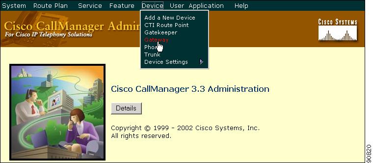
Figure 6-2 Cisco CallManager Administration Device Menu
The Find and List Gateways window displays.
Step 2
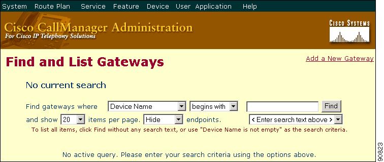
Figure 6-3 Find and List Gateways Window
Step 3
A list of discovered devices displays.
Step 4
The Gateway Configuration window appears.
Step 5
Step 6
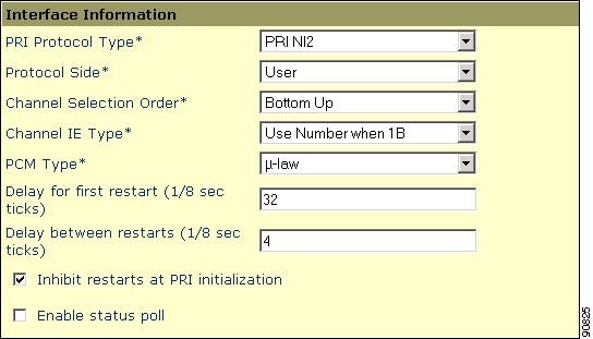
Figure 6-4 Interface Information Window
Step 7
Step 8
Step 9
Note
For detailed information on E1/T1 PRI configuration settings, refer to the Cisco CallManager Administration Guide.
B-Channel Remains Locked When Restart_Ack Does Not Contain Channel IE
Symptom
This issue relates to the previous issue: Cisco CallManager Locks the B-Channel and Sends Restart.
When the Cisco CallManager system receives a Release Complete with cause ie=channel not available, the system sends out a Restart to bring this channel back to the idle state.
Probable Cause
In the Restart, you specify with the Channel IE which channel(s) must be restarted. If the network responds with Restart_Ack without the Channel IE, the system keeps this channel in a locked state. While on network side, this same channel goes back to idle state.
Now you end up with the network requesting this channel for inbound calls.
Because the channel is locked on the Cisco CallManager server, the Cisco CallManager releases any call requests for this channel.
This behavior occurs on numerous sites in the UK and when the gateway is an E1 blade (most likely the same happens when using MGCP backhaul on the 2600/3600).
A glare condition provides the likely reason for the Release Complete.
You see this frequent happening on sites where a high call volume occurs.
If the B-channel selection on the network is top-down or bottom up, all inbound calls will fail until a B-channel in the higher/lower range is freed (if an active call gets cleared).
When B-channel selection is round-robin over a certain time, you will end up with an E1 blade with all locked B-channels.
Corrective Action
Reset the E1 port.
Verification
The B-channel(s) return to the idle state.