-
Cisco CallManager System Guide, Release 4.0(1)
-
Index
-
Preface
-
Introduction
-
Cisco IP Telephony Overview
-
System Configuration Overview
-
Multilevel Administration Access
-
System-Level Configuration Settings
-
Clustering
-
Redundancy
-
Call Admission Control
-
Cisco TFTP
-
Device Support
-
Services
-
Auto-Registration
-
Partitions and Calling Search Spaces
-
Understanding Route Plans
-
Application Dial Rules Overview
-
Understanding the LDAP Directory
-
Managing User Directory Information
-
Media Resource Management
-
Annunciator
-
Conference Bridges
-
Transcoders
-
Music On Hold
-
Media Termination Points
-
Cisco DSP Resources for Transcoding, Conferencing, and MTP
-
Voice Mail Connectivity to Cisco CallManager
-
SMDI Voice Mail Integration
-
Cisco Unity Messaging Integration
-
Cisco DPA Integration
-
Call Park
-
Call Pickup and Group Call Pickup
-
Cisco IP Phone Services
-
Cisco CallManager Extension Mobility and Phone Login Features
-
Cisco CallManager Attendant Console
-
Cisco IP Manager Assistant
-
Understanding Cisco CallManager Voice Gateways
-
Understanding IP Telephony Protocols
-
Understanding Session Initiation Protocol (SIP)
-
Understanding Cisco CallManager Trunk Types
-
Cisco IP Phones
-
Understanding Video Telephony
-
Computer Telephony Integration
-
Cisco ATA 186 and Cisco ATA 188
-
Administrative Tools Overview
-
Administrative Accounts and Passwords
-
 Feedback
Table Of Contents
Understanding IP Telephony Protocols
Media Gateway Control Protocol (MGCP)
Skinny Client Control Protocol (SCCP)
Session Initiation Protocol (SIP)
Channel Associated Signaling (CAS)
T1 Primary Rate Interface (T1 PRI)
E1 Primary Rate Interface (E1 PRI)
Message Waiting Indication Services
QSIG Interface to Cisco CallManager
Where to Find More Information
Understanding IP Telephony Protocols
Understanding IP Telephony Protocols briefly describes some of the different protocols and their interaction with Cisco CallManager.
This section covers the following topics:
•
Where to Find More Information
IP Protocols
Cisco CallManager performs signaling and call control tasks such as digit analysis, routing, and circuit selection within the PSTN gateway infrastructure. To perform these functions, Cisco CallManager uses industry standard IP protocols including H.323, MGCP, SCCP, and SIP. Use of Cisco CallManager and these protocols gives service providers the capability to seamlessly route voice and data calls between the PSTN and packet networks.
Four IP protocols are discussing in this section:
•
•
•
H.323 Protocol
The International Telecommunications Union (ITU) developed the H.323 standard for multimedia communications over packet networks. As such, the H.323 protocol is a proven ITU standard and provides multivendor interoperability. The H.323 protocol specifies all aspects of multimedia application services, signaling, and session control over an underlying packet network. Audio is standard on H.323 networks, but networks can be scaled to include both video and data. The H.323 protocol can be implemented in large enterprise networks or can be deployed over an existing infrastructure, which makes H.323 an affordable solution.
The basic components of the H.323 protocol are terminals, gateways, and gatekeepers (which provide call control to H.323 endpoints). Similar to other protocols, H.323 applies to point-to-point or multipoint sessions. However, compared to MGCP, H.323 requires more configuration on the gateway.
For more information, refer to the following topics:
•
•
•
•
•
Media Gateway Control Protocol (MGCP)
MGCP provides Cisco CallManager a powerful, flexible and scalable resource for call control. Cisco CallManager uses MGCP to control media on the telephony interfaces of a remote gateway and also uses MGCP to deliver messages from a remote gateway to appropriate devices.
MGCP enables a call agent (media gateway controller) to remotely control and manage voice and data communication devices at the edge of multiservice IP packet networks. Because of its centralized architecture, MGCP simplifies the configuration and administration of voice gateways and supports multiple (redundant) call agents in a network. MGCP does not provide security mechanisms such as message encryption or authentication.
Using MGCP, Cisco CallManager controls call processing and routing and provides supplementary services to the gateway. The MGCP gateway provides call preservation (the gateway maintains calls during failover and fallback), redundancy, dial-plan simplification (the gateway requires no dial-peer configuration), hookflash transfer, and tone on hold. MGCP-controlled gateways do not require a media termination point (MTP) to enable supplementary services such as hold, transfer, call pickup, and call park. If the MGCP gateway loses contact with its Cisco Call Manager, it falls back to using H.323 control to support basic call handling of FXS, FXO, T1 CAS, and T1/E1 PRI interfaces.
For more information, refer to the "Adding a Cisco IOS MGCP Gateway" section in the Cisco CallManager Administration Guide.
Related Topics
•
•
Skinny Client Control Protocol (SCCP)
SCCP uses Cisco-proprietary messages to communicate between IP devices and Cisco CallManager. SCCP easily coexists in a multiple protocol environment. The Cisco IP Phone is an example of a device that registers and communicates with Cisco CallManager as an SCCP client. During registration, a Cisco IP phone receives its line and all other configurations from Cisco CallManager. Once it registers, it is notified of new incoming calls and can make outgoing calls. The SCCP protocol is used for VoIP call signaling and enhanced features such as Message Waiting Indication (MWI).
The Cisco VG248 gateway is another example of a device that registers and communicates with Cisco CallManager by using SCCP. For more information, on the Cisco VG248 gateway refer to the "Adding a Cisco VG248 Analog Phone Gateway"section in the Cisco CallManager Administration Guide.
Related Topics
•
•
Session Initiation Protocol (SIP)
The Internet Engineering Task Force (IETF) developed the SIP standard for multimedia calls over IP. ASCII-based SIP works in client/server relationships as well as in peer-to-peer relationships. SIP uses requests and responses to establish, maintain, and terminate calls (or sessions) between two or more end points. Refer to the Understanding Session Initiation Protocol (SIP) chapter for more information on SIP and the interaction between SIP and Cisco Call Manager.
Related Topics
•
•
Analog Telephony Protocols
Analog telephony signaling, the original signaling protocol, provides the method for connecting or disconnecting calls on analog trunks. By using direct current (DC) over two-wire or four-wire circuits to signal on-hook and off-hook conditions, each analog trunk connects analog endpoints or devices such as a PBX or analog phone.
To provide connections to legacy analog central offices and PBXs, Cisco CallManager uses analog signaling protocols over analog trunks that connect voice gateways to analog endpoints and devices . Cisco CallManager supports these types of analog trunk interfaces:
•
•
You can configure loop-start, ground-start, or E&M signaling protocols for FXO and FXS trunk interfaces depending on the gateway model that is selected. You must use the same type of signaling on both ends of the trunk interface to ensure that the calls properly connect. The following sections describe the types of analog signaling protocols that Cisco CallManager supports:
•
Loop-Start Signaling
Loop-start signaling sends an off-hook signal that starts a call and an on-hook signal that closes the loop and ends the call. Loop-start trunks lack positive disconnect supervision, and users can experience glare when two calls seize the trunk at the same time.
Related Topics
•
Ground-Start Signaling
Ground-start signaling provides current detection mechanisms at both ends of the trunk to detect off-hook signals. This mechanism permits endpoints to agree on which end is seizing the trunk before it is seized, and minimizes the chance of glare. Ground start provides positive recognition of connects and disconnects and is the preferred signaling method for PBX connections. Some PBXs do not support ground-start signaling, so then you must use loop-start signaling for the trunk interface.
Related Topics
•
E&M Signaling
E&M signaling uses direct current (DC) over two-wire or four-wire circuits to signal to the endpoint or CO switch when a call is in recEive or transMit (E&M) state. E&M signaling uses signals that indicate off-hook and on-hook conditions. When the connection is established, the audio transmission occurs. The E&M signaling type must be the same for both ends of the trunk interface for successful connections. Cisco CallManager supports these types of E&M signaling:
Wink-start signaling—The originating side sends an off-hook signal and waits to receive a wink pulse signal that indicates the receiving end is ready to receive the dialed digits for the call. Wink start is the preferred signaling method because it provides answer supervision. Not all COs and PBXs support wink-start signaling.
Delay-dial signaling—The originating side sends an off-hook signal, waits for a configurable time period, and then checks if the receiving end is on hook. The originating side sends dialed digits when the receiving side is on hook. The delay allows the receiving end to signal when it is ready to receive the call.
Immediate-start signaling—The originating side goes off hook, waits for a finite time period ( for example 200 ms), and then sends the dial digits without a ready signal from the receiving end.
Related Topics
•
Channel Associated Signaling (CAS)
Channel associated signaling (CAS) sends the on hook and off hook signals as bits within the frames on the same channel as the audio transmission. CAS is often referred to as robbed bit signaling because CAS takes bits from the voice channel for signaling. These signals can include supervision, addressing, and tones such as busy tone or dial tone.
You can use T1 CAS and E1 CAS digital trunk interfaces to connect a Cisco CallManager call to a CO, a PBX, or other analog device.
T1 CAS
The T1 CAS trunk interface uses in-band E&M signaling to carry up to 24 connections on a link. Both ends of the T1 link must specify T1 CAS signaling. Cisco CallManager provides the T1 CAS signaling option when you configure ports on some MGCP and H.323 voice gateways and network modules. For more information about supported gateways, see the "Voice Gateway Model Summary" section.
E1 CAS
Some Cisco gateways in H.323 mode can support the E1 CAS trunk interface that provides up to 32 connections on the link. You must configure the E1 CAS signaling interface on the gateway, not in Cisco CallManager Administration. Both ends of the E1 link must specify E1 CAS signaling. For a list of H.323 gateways that support E1 CAS, see the "Voice Gateway Model Summary" section. Refer to documentation for the specific gateway for configuration information.
Related Topics
Digital Telephony Protocols
Digital telephony protocols use common channel signaling (CCS), a dedicated channel that carries only signals. In a T1 link, one channel carries the signals while the other channels carry voice or data. The latest generation of CCS is known as Signaling System 7 (SS7) and provides supervision, addressing, tones, and a variety of services such as automatic number identification (ANI).
Integrated Services Digital Network (ISDN) is a set of international standards for user access to private or public network services. ISDN provides both circuit-based and packet-based communications to users.
Cisco CallManger can support these ISDN protocols:
•
•
Basic Rate Interface (BRI)
Basic rate interface (BRI) , which is used for small office and home communications links, provides two B-channels for voice and data and one D-channel for signaling.
Related Topics
•
•
T1 Primary Rate Interface (T1 PRI)
T1 Primary rate interface (PRI) is used for corporate communications links in North America and Japan. T1 PRI provides 23 B-channels for voice and data and one D-channel for common channel signaling. T1 PRI uses a communication rate of 1.544Mbps.
Related Topics
•
E1 Primary Rate Interface (E1 PRI)
E1 PRI Primary rate interface (PRI) is used for corporate communications in Europe. E1 PRI provides 30 B-channels for voice and data , one D-channel for common signaling, and one framing channel. E1 PRI uses a rate of 2.048 Mbps.
Related Topics
•
Q.Signaling (QSIG)
The QSIG protocol is a series of international standards that define services and signaling protocols for Private Integrated Services Networks (PISNs). These standards use ISDN concepts and conform to the framework of International Standards for Open Systems Interconnection as defined by ISO/IEC. The QSIG protocol is a variant of ISDN D-channel voice signaling. It is based on the ISDN Q.921 and Q.931 standards and is a worldwide standard for PBX interconnection.
The integration of QSIG protocol support with voice over IP (VoIP) enables Cisco voice switching services to connect to PBX's, key systems, and central office (CO) switches that communicate by using QSIG protocol. Cisco devices can route incoming voice calls from a private integrated services network exchange (PINX) device across a WAN to a peer Cisco device that can transport the signaling and voice packets to a second PINX device. PINX devices can be PBXs, key systems, or Cisco CallManager nodes that support QSIG protocol.
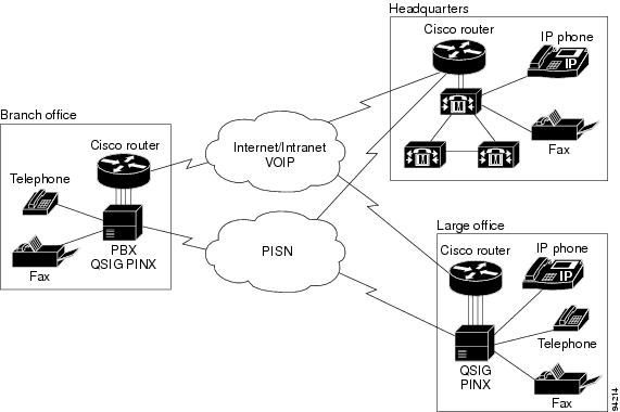
In a network that supports QSIG protocol, a user in a PINX can place a call to a user that is in a remote PINX. The called party receives the caller's name or number as the call rings. If the called party is not available, the call forwards to another destination or to a voice-messaging system. All the features that are available as a PBX user operate transparently across the network. QSIG protocol provides supplementary and additional network features, as defined for PISNs. Figure 36-1 shows an example of a QSIG multi-vendor network with PBX systems and Cisco CallManager systems.
Figure 36-1 Multi-Vendor Private Integrated Services Network (PISN) Using QSIG
Cisco CallManager provides a limited set of QSIG features and services. Keep in mind that all other PBXs in the network must be able to support the same feature set to make supplementary features available to all network user. Cisco CallManager supports these QSIG features and services:
•
QSIG Basic Call
QSIG basic call setup provides the dynamic establishment of voice connections from an originating PINX (PBX or Cisco CallManager), across a private network or virtual private network (VPN) using the PSTN, to another PINX. You must use digital T1 or E1 primary rate interface (PRI) trunks to support QSIG protocol.
Identification Services
Cisco CallManager provides configuration settings to control the following caller identification number (CLID) and caller name (CNAM) information on phone displays:
•
•
•
•
Cisco CallManager Administration provides flexible configuration options to control the display of caller identification information. You can allow or restrict the display of this information for all calls by using fields in the Gateway Configuration window. Or, you can control the display of this information on a call-by-call basis by using fields in the Route Patterns and Translation Patterns windows. For information about configuring QSIG identification services, see the "Caller Identification and Restriction" section.
Message Waiting Indication Services
In a QSIG network, when a PINX has a connected voice-messaging system that services users in another PINX, the message center PINX can send the following message waiting indication (MWI) signals to the other PINX:
•
•
Note
A PINX that is not a message center can receive MWI signals and perform the following:
•
•
If the voice-messaging system is connected to Cisco CallManager by using QSIG connections or by using the Cisco Messaging Interface (CMI), the message waiting indicators are set based on QSIG directives.
When a call is forwarded to another number and then diverted to a voice-messaging system, QSIG supplementary services can provide the information to place the voice message in the originally called party's voice mailbox.
The Message Waiting Indication service uses the existing dial number for message waiting that is set up in Cisco CallManager Administration, and does not require any additional configuration.
Call Diversion (Forwarding)
The QSIG standards describe two methods for call diversion: Call diversion by reroute and call diversion by forward switching. Cisco CallManager supports call diversion by forward switching only.
QSIG diversion supplementary services provide call forwarding capabilities that are similar to the familiar Cisco CallManager call forwarding features. The user or the system administrator can activate any of these features on individual directory numbers. Call forwarding supplementary services include the following:
•
•
•
Note
QSIG provides information to the originating PINX about the status and destination of outbound calls. Information about a forwarded call is passed during the call setup and connection over QSIG trunks in order to provide feature transparency with other PBXs in the network. Phone displays can present calling name/number and called name/number information to show the destination of the forwarded call.
When calls are forwarded between multiple PINXs, a forwarding loop can result. To avoid calls being caught in a looping condition, or entering a long forwarding chain, a hop counter limits this possibility. You can configure the Forward Maximum QSIG Hop Count parameter in Cisco CallManager Service Parameters.
QSIG supplementary services can provide the information to place the voice message from a diverted call in the originally called party's voice mailbox.
Call Transfer
The QSIG standards describe two methods for transfering calls: Call transfer by reroute and call transfer by join. Cisco CallManager provides for call transfer over QSIG trunks by join only.
When a user transfers a call to another user, QSIG identification service provides for changing the connected name and number on the transferred party's phone display. Call transfer requires no additional configuration in Cisco CallManager Administration.
QSIG Interface to Cisco CallManager
For Cisco CallManager to support QSIG functionality, QSIG must be back-hauled directly to Cisco CallManager. Cisco CallManager interconnects to a QSIG network by using an MGCP gateway and T1 or E1 PRI connections to the PISN. The MGCP gateway establishes the call connections. By using the PRI backhaul mechanism, the gateway passes the QSIG messages to Cisco CallManager to enable setting up QSIG calls and sending QSIG messages to control features.
When a PBX is connected to a gateway that is using QSIG via H.323, calls that are made between phones on the PBX and IP phones attached to the Cisco CallManager can have only basic PRI functionality. The gateway that terminates the QSIG protocol provides only the Calling Line Identification (CLID) and Direct Inward Dialed (DID) number rather than Cisco CallManager providing the information.
Related Topics
•
•
Where to Find More Information
Related Topics
•
•
•
•
Additional Cisco Documentation
•
•
•