-
Cisco CallManager System Guide, Release 3.1(1)
-
Index
-
Preface
-
Introduction
-
Cisco IP Telephony Overview
-
System Configuration Overview
-
System-Level Configuration Settings
-
Clustering
-
Redundancy
-
Call Admission Control
-
Cisco TFTP
-
Device Support
-
Services
-
Auto-Registration
-
Partitions and Calling Search Spaces
-
Understanding Route Plans
-
Understanding the LDAP Directory
-
Managing User Directory Information
-
Media Resource Management
-
Conference Bridges
-
Transcoders
-
Music On Hold
-
Media Termination Points
-
Catalyst DSP Resources for Transcoding and Conferencing
-
SMDI Voice Mail Integration
-
Cisco Unity Messaging Integration
-
Cisco uOne Voice Messaging Integration
-
Cisco DPA Integration
-
Call Park
-
Call Pickup and Group Call Pickup
-
Cisco IP Phone Services
-
Extension Mobility and Phone Login Features
-
Understanding Cisco WebAttendant
-
Custom Phone Rings
-
Understanding Voice Gateways
-
Cisco IP Phones
-
Computer Telephony Integration
-
Administrative Tools Overview
-
Administrative Accounts and Passwords
-
 Feedback
Table Of Contents
SMDI Voice Mail Integration Requirements
Where To Find More Information
SMDI Voice Mail Integration
Simplified Message Desk Interface (SMDI) defines a way for a phone system to provide voice-mail systems with the information needed to intelligently process incoming calls. Each time the phone system routes a call, it sends an EIA/TIA-232 message to the voice-mail system that tells it the line it is using, the type of call it is forwarding, and information about the source and destination of the call.
The SMDI-compliant voice-mail system connects to Cisco CallManager in two ways:
•
Using a standard serial connection to the Cisco CallManager
•
This section covers the following topics:
•
SMDI Voice Mail Integration Requirements
The Cisco Messaging Interface service allows you to use an external voice-mail system with the Cisco CallManager 3.0 and later.
The voice-mail system must meet the following requirements:
•
•
•
•
•
Port Configuration for SMDI
Previous releases of Cisco CallManager required a specific configuration for voice-mail integration using the SMDI and the Cisco Messaging Interface. This older configuration method for FXS ports required each individual port of an analog access gateway (Cisco AS-2, Cisco AS-4, Cisco AS-8, or Cisco Catalyst 6000 24 Port FXS gateway) to be explicitly configured as a separate entry in a route group. The relative position within the route list/route group of each analog access port determined the SMDI port number reported by the Cisco Messaging Interface.
Beginning with Cisco CallManager Release 3.0(5), you can configure the SMDI port number through Cisco CallManager Administration.
Note
To use the new SMDIPortNumber configuration, perform the following steps:
1.
With this first step, you do not need to change any route lists/route groups. The newly configured SMDIPortNumber(s) override any existing route list/route group configuration that was set up for the devices that connect to the voice-mail system.
2.
The selection order of each of these device entries can be the same or different.
ReorderRouteList Service Parameter
An added mechanism allows selecting devices in a route group in a "round-robin" fashion. To take advantage of this feature, configure the devices as follows:
1.
2.
When a call is extended via the route list, Cisco CallManager offers it to the devices in the route group in sequential order. Then, Cisco CallManager re-orders the device list (route group) by taking the first device in the list and moving it to the end of the list.
The next call extended via the route list receives the re-ordered list, and thus extends the call to a different device (compared to the previous call). Each call attempt communicates with a subsequent device first. With this mechanism, use all devices in the group in a "round-robin" fashion instead of the current "top-down" only mechanism.
Enabling the ReorderRouteList service parameter does not affect route list/route configurations that have explicitly set different selection orders for devices in a route group for setting up an ordered device selection (that is, the older method of voice-mail configuration).
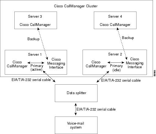
CMI Redundancy
Most voice-mail systems relying on an EIA/TIA-232 serial cable (previously known as a RS-232 cable) to communicate with phone systems only have one serial port. You can achieve CMI redundancy by running two or more copies of the Cisco Messaging Interface service on different servers in a Cisco CallManager cluster and using additional hardware including a data splitter described later in this section.
Each copy of CMI connects to a primary and backup Cisco CallManager and registers to the Cisco CallManager using the same VoiceMailDn and VoiceMailPartition service parameter values. The CMI with the higher service priority (the active CMI service) handles the SMDI responsibilities. If this CMI encounters problems, another one can take over. Figure 22-1 illustrates one of many layouts that provides CMI redundancy.
Figure 22-1 CMI Redundancy
Note
The data splitter you connect to your voice-mail system, such as the B&B Electronics modem data splitter (models 232MDS and 9PMDS), must have the following characteristics:
•
•
•
•
•
The 232MDS has two DB25 male ports and one DB25 female port. The 9PMDS is a DB9 version of this modem data splitter. These switches enable CMI redundancy with the following limitations when you set the ValidateDNs CMI service parameter to Off:
•
•
SMDI Configuration Checklist
Table 22-1 provides an overview of the steps required to integrate voice-mail systems using SMDI:
Table 22-1 SMDI Configuration Checklist
Step 1
Add and configure gateway ports.
If you are configuring an Octel system and you are using a Cisco Catalyst 6000 24 Port FXS Analog Interface Module or AST ports, make sure to set the Call Restart Timer field on each port to 1234.
Adding Gateways to Cisco CallManager, Cisco CallManager Administration Guide
Step 2
Create a route group, and add the gateway ports you configured in Step 1 to the route group.
Adding a Route Group, Cisco CallManager Administration Guide
Step 3
Create a route list containing the route group configured in Step 2.
Adding a Route List, Cisco CallManager Administration Guide
Step 4
Create a route pattern.
Adding a Route Pattern, Cisco CallManager Administration Guide
Step 5
Install and configure the Cisco Messaging Interface service.
Service Parameters Configuration, Cisco CallManager Administration Guide
Step 6
Configure CMI trace parameters.
Cisco CallManager Serviceability Administration Guide
Step 7
Configure your voice-mail system, and connect the voice-mail system to Cisco CallManager with an EIA/TIA-232 cable.
Refer to the documentation provided with your system.
Where To Find More Information
Additional Cisco Documentation
•
•
•
•