-
Cisco CallManager System Guide, Release 3.1(1)
-
Index
-
Preface
-
Introduction
-
Cisco IP Telephony Overview
-
System Configuration Overview
-
System-Level Configuration Settings
-
Clustering
-
Redundancy
-
Call Admission Control
-
Cisco TFTP
-
Device Support
-
Services
-
Auto-Registration
-
Partitions and Calling Search Spaces
-
Understanding Route Plans
-
Understanding the LDAP Directory
-
Managing User Directory Information
-
Media Resource Management
-
Conference Bridges
-
Transcoders
-
Music On Hold
-
Media Termination Points
-
Catalyst DSP Resources for Transcoding and Conferencing
-
SMDI Voice Mail Integration
-
Cisco Unity Messaging Integration
-
Cisco uOne Voice Messaging Integration
-
Cisco DPA Integration
-
Call Park
-
Call Pickup and Group Call Pickup
-
Cisco IP Phone Services
-
Extension Mobility and Phone Login Features
-
Understanding Cisco WebAttendant
-
Custom Phone Rings
-
Understanding Voice Gateways
-
Cisco IP Phones
-
Computer Telephony Integration
-
Administrative Tools Overview
-
Administrative Accounts and Passwords
-
 Feedback
Table Of Contents
Locations Configuration Checklist
Components of Gatekeeper Call Admission Control
Gatekeeper Configuration on the Router
Gatekeeper Configuration in Cisco CallManager
Gatekeeper Configuration Checklist
Where to Find More Information
Call Admission Control
Call admission control enables you to control the audio quality of calls over a wide-area (IP WAN) link by limiting the number of calls allowed on that link at the same time. For example, you can use call admission control to regulate the voice quality on a 56 kbps Frame Relay line connecting your main campus and a remote site.
Audio quality can begin to degrade when there are too many active calls on a link and the amount of bandwidth is oversubscribed. Call admission control regulates audio quality by limiting the number of calls that can be active on a particular link at the same time. Call admission control does not guarantee a particular level of audio quality on the link, but it does allow you to regulate the amount of bandwidth consumed by active calls on the link.
This section describes two types of call admission control that you can use with Cisco CallManager:
•
Locations, for systems with centralized call processing
•
You can choose either of these two methods of call admission control, but you cannot combine them in the same Cisco CallManager system. If your system does not contain IP WAN links with limited available bandwidth, you do not have to use call admission control.
Locations
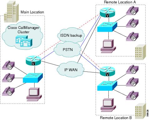
The locations feature, available in Cisco CallManager, provides call admission control for centralized call processing systems. A centralized system uses a single Cisco CallManager cluster to control all the locations. Figure 7-1 illustrates call admission control using locations. For more information, refer to the "Location Configuration" section in the Cisco CallManager Administration Guide and to the Cisco IP Telephony Network Design Guide.
Figure 7-1 Call Admission Control Using Locations in a Centralized System
In a centralized call processing system, as illustrated in Figure 7-1, the Cisco CallManager cluster resides at the main location, along with other devices such as phones and gateways. The remote locations (for example, branch offices of your company) house additional phones and other devices, but they do not contain any call processing capability. The remote locations connect to the main location and to each other by means of IP WAN links (and possibly PSTN and ISDN links as backups).
Calls between devices at the same location do not need call admission control because those devices reside on the same LAN, which has unlimited available bandwidth. However, calls between devices at different locations must travel over an IP WAN link, which has limited available bandwidth. The locations feature in Cisco CallManager lets you specify the maximum amount of bandwidth available for calls to and from each location, thereby limiting the number of active calls and preventing oversubscription of the bandwidth on the IP WAN links.
For location bandwidth calculations, Cisco CallManager assumes that each call consumes the following amount of bandwidth:
•
•
•
•
•
For example, assume that you have configured the following locations in Cisco CallManager Administration:
San Francisco (main location)
Unlimited
Austin (remote location)
100
Dallas (remote location)
200
Cisco CallManager continues to admit new calls to a link as long as sufficient bandwidth is still available. Thus, if the link to the Austin location in our example has 100 kbps of available bandwidth, that link can support one G.711 call at 80 kbps, four G.723 or G.729 calls at 24 kbps each, or three GSM calls at 29 kbps each. If any additional calls try to exceed the bandwidth limit, the system rejects them, the calling party receives reorder tone, and a text message displays on the phone.
When you configure a location in Cisco CallManager Administration, you assign it a name and maximum bandwidth. If you enter a value of zero (0) for the bandwidth, you allocate unlimited available bandwidth and allow an unlimited number of active calls on the IP WAN link for that location.
When you configure a phone or other device in Cisco CallManager Administration, you can assign it to a location. If you set the location to None, you assign that device to an unnamed location with unlimited available bandwidth and allow an unlimited number of active calls to and from that device.
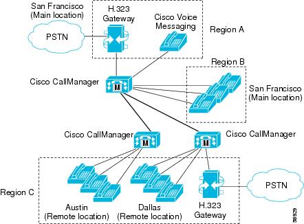
Locations and Regions
Locations work in conjunction with regions to define the characteristics of a network link. Regions define the type of compression (G.711, G.723, or G.729) used on the link, and locations define the amount of available bandwidth for the link. You must assign each device in the system to both a region (by means of a device pool) and a location. As illustrated in Figure 7-2, the regions and locations can overlap and intersect in various ways, depending on how you define them. For more information, see the "Regions" section.
Figure 7-2 Interaction Between Locations and Regions
Bandwidth Calculations
In performing bandwidth calculations for purposes of call admission control, Cisco CallManager assumes that all calls are full-duplex connections. Cisco CallManager also assumes that each call consumes the following amount of bandwidth:
•
•
•
•
•
Note
Cisco CallManager allows calls to complete over a link until there is no longer sufficient bandwidth for a new call. At that point, any additional calls fail and the calling party receives reorder tone.
A Media Termination Point (MTP) is one exception to the bandwidth rules outlined in the preceding paragraph. Calls made through an MTP can complete even if they exceed the available bandwidth limit.
Caution
Locations Configuration Checklist
Table 7-1 lists the general steps for configuring call admission control based on locations.
Table 7-1 Locations Configuration Checklist
Step 1
Configure a region for each type of codec used in your system.
See the "Locations and Regions" section.
Refer to the "Region Configuration" section in Cisco CallManager Administration Guide.
Step 2
Configure a separate location for each IP WAN link to which you want to apply call admission control. Allocate the maximum available bandwidth for calls across the link to that location.
Note
Refer to the "Location Configuration" section in the Cisco CallManager Administration Guide.
Step 3
Configure the device pools for your system and select the appropriate region for each.
Refer to the "Device Pool Configuration" section in the Cisco CallManager Administration Guide.
Step 4
Configure the phones and other devices, and assign each of them to the appropriate device pool and location.
Note
See the "Cisco IP Phones" section.
Refer to the "Cisco IP Phone Configuration" section in the Cisco CallManager Administration Guide.
Gatekeeper
A gatekeeper device, the Cisco Multimedia Conference Manager (MCM), provides call admission control for distributed call processing systems. In a distributed system, each site contains its own call processing capability. For example, Figure 7-3 shows two sites, each with its own Cisco CallManager, connected by and IP WAN link. The gatekeeper provides call admission control over the IP WAN link in this example.
In addition to call admission control, the gatekeeper can also perform E.164 address resolution to route calls between the sites. For example, in Figure 7-3, one Cisco CallManager has an extension range of 1XXX and the other 2XXX. Both register with the gatekeeper for call admission control. Each Cisco CallManager has an appropriate entry in its respective dial plan route pattern configuration that points the other Cisco CallManager extension number range to the gatekeeper. In practice, when user 1001 dials user 2002, Cisco CallManager 1XXX sends 2002 to the gatekeeper for address resolution. If the call satisfies the call admission control criteria, the gatekeeper returns the IP address of Cisco CallManager 2XXX to Cisco CallManager 1XXX. Using the IP address of Cisco CallManager 2XXX, Cisco CallManager 1XXX can then complete the call to directory number 2002.
Figure 7-3 Call Admission Control Using a Gatekeeper in a Distributed System
If the IP WAN is not available in this scenario, the call cannot go through as dialed. To simplify the dial plan and also provide fallback to the PSTN, use 10-digit dialing (or adhere to the national dial plan). For example, under the North American Numbering Plan (NANP), a route pattern of XXXXXXXXXX would direct calls to the gatekeeper (Anonymous Calls Device) for address resolution. If the gatekeeper does not allow the call to go over the WAN, then Cisco CallManager can add the prefix 91 to the dialed digits to reroute the call through the PSTN.
Refer to the Cisco IP Telephony Network Design Guide for more detailed information about gatekeeper configuration, dial plan considerations when using a gatekeeper, and gatekeeper interaction with Cisco CallManager.
Components of Gatekeeper Call Admission Control
Gatekeeper call admission control is very flexible:
•
•
•
•
•
The following sections describe the components of gatekeeper call admission control:
•
•
Gatekeeper Configuration on the Router
Recommended platforms for the gatekeeper include Cisco 2600, 3600, or 7200 routers with Cisco IOS Release 12.1(3)T or higher. When configuring the gatekeeper function on one of these routers, you define a set of zones for call admission control. Each zone has a unique name and includes the IP address of each Cisco CallManager that registers with that zone, the zone prefix (directory number range), and the bandwidth allocated for that zone.
Cisco CallManager registers with the gatekeeper using its IP address. You can specify the IP address in one of the following ways:
•
•
You can associate the Cisco CallManager IP address with a particular zone in one of the following ways:
•
•
To specify the directory number range for a particular Cisco CallManager, you configure the range on the gatekeeper using the zone prefix command. For example, the following command specifies that zone LHR has a DN range of 3000 to 3999.
zone prefix LHR 3...The maximum number of active calls allowed per zone depends on the codec used for each call and the bandwidth allocated for the zone. With Cisco CallManager, G.711 calls request 128 kbps and G.723 and G.729 calls request 20 kbps. Use regions in Cisco CallManager to specify the type of codec, and use the zone bw command on the gatekeeper to specify the available bandwidth. For example, the following command allocates 512 kbps to the LHR zone.
zone bw LHR 512With an allocation of 512 kbps, the LHR zone in this example could support up to four G.711 calls at the same time.
For more information on programming the gatekeeper, refer to the Cisco Multimedia Conference Manager documentation.
Gatekeeper Configuration in Cisco CallManager
You can configure the gatekeeper in Cisco CallManager administration to function in either of the following ways.
Call Admission Control Only
In this case, you explicitly configure a separate intercluster trunk or H.225 gateway for each remote device that the local Cisco CallManager can call over the IP WAN. You also configure the necessary route patterns and route groups to route calls to and from the various intercluster trunks or H.225 gateways. The intercluster trunks and H.225 gateways statically specify the IP addresses of the remote devices. Use this method only for small systems, where the number of remote connections is minimal. To select this method, uncheck the Allow Anonymous Calls check box under Device > Gatekeeper.
Call Admission Control Plus IP Address Resolution (Call Routing)
In this case, you configure only the gatekeeper settings in Cisco CallManager and not the intercluster trunks or H.225 gateways. You also configure route patterns or route groups to route the calls to and from the gatekeeper, but this method generally requires fewer route patterns than when you use intercluster trunks or H.225 gateways. In this configuration, the gatekeeper dynamically determines the appropriate IP address for the destination of each call to a remote device, and the local Cisco CallManager uses that IP address to complete the call. Use this method for large systems or small ones as well. To select this method, check the Allow Anonymous Calls check box under Device > Gatekeeper.
If you enable the Allow Anonymous Calls option, Cisco CallManager automatically creates a virtual device called AnonymousDevice. The IP address of this AnonymousDevice changes dynamically to reflect the IP address of the remote device as determined by the gatekeeper. Use the AnonymousDevice when configuring the route patterns or route groups that route calls to and from the gatekeeper.
Gatekeeper Configuration Checklist
Table 7-2 lists the general steps for configuring call admission control based on a gatekeeper.
Table 7-2 Gatekeeper Configuration Checklist
Step 1
On the gatekeeper device, configure the appropriate zones and bandwidth allocations for the various Cisco CallManagers that will route calls to it.
Refer to your Cisco Multimedia Conference Manager documentation.
Step 2
Configure the gatekeeper settings in Cisco CallManager Administration. If you enable the Allow Anonymous Calls option, skip Step 3.
Repeat this step for each Cisco CallManager that will register with the gatekeeper. Make sure Gatekeeper Name and Allow Anonymous Calls are set the same way on each Cisco CallManager.
Refer to the "Gatekeeper Configuration" section in the Cisco CallManager Administration Guide.
Step 3
If you did not enable the Allow Anonymous Calls option, configure the appropriate intercluster trunks or H.225 gateways to specify the IP addresses of the remote devices registered with the gatekeeper.
See the "H.323 Gateways" section.
Refer to the "Adding a Cisco IOS H.323 Gateway or Intercluster Trunk" section in the Cisco CallManager Administration Guide.
Step 4
Configure a route pattern to route calls to the gatekeeper.
See the "Understanding Route Plans" section.
Refer to the "Route Pattern Configuration" section in the Cisco CallManager Administration Guide.
Where to Find More Information
Related Topics
•
•
•
•
Additional Cisco Documentation
•
http://www.cisco.com/univercd/cc/td/doc/product/voice/ip_tele/network/
•