|
Table Of Contents
Cisco Unified CallManager 5.0 SIP Trunk Integration Guide for Cisco Unity Connection 1.1
Task List to Create the Integration by a SIP Trunk
Task List to Change the Number of Voice Messaging Ports
Task List to Add a Cisco Unified CallManager Express Server to a Cisco Unified CallManager Cluster
Integrations with Multiple Phone Systems
Planning How the Voice Messaging Ports Will Be Used by Cisco Unity Connection
Programming the Cisco Unified CallManager Phone System
Creating a New Integration with the Cisco Unified CallManager Phone System
(Multiple Integrations Only) Adding New User Templates
Changing the Number of Voice Messaging Ports
Appendix: Documentation and Technical AssistanceCisco Product Security Overview
Reporting Security Problems in Cisco Products
Product Alerts and Field Notices
Obtaining Technical Assistance
Definitions of Service Request Severity
Obtaining Additional Publications and Information
Cisco Unified CallManager 5.0 SIP Trunk Integration Guide for Cisco Unity Connection 1.1
Revised December 8, 2006
This document provides instructions for integrating the Cisco Unified CallManager phone system with Cisco Unity Connection by a SIP trunk.
Cisco Unity Connection supports a SIP trunk integration with the Cisco Unified CallManager phone system when the Cisco Unified CallManager phone system has only SIP phones.
Note If you are configuring MWI relay across trunks in a distributed phone system, you must refer to the Cisco Unified CallManager documentation for requirements and instructions. Configuring MWI relay across trunks does not involve Cisco Unity Connection settings.
Integration Tasks
Before doing the following tasks to integrate Cisco Unity Connection with the Cisco Unified CallManager phone system, confirm that the Cisco Unity Connection server is ready for the integration by completing the applicable tasks in the Cisco Unity Connection Installation Guide.
The following task lists describe the process for creating, changing, and deleting integrations.
Task List to Create the Integration by a SIP Trunk
Use the following task list to set up a new integration with the Cisco Unified CallManager phone system. If you are installing a new Cisco Unity Connection server by using the Cisco Unity Connection Installation Guide, you may have already completed some of the following tasks.
1. Review the system and equipment requirements to confirm that all phone system and Cisco Unity Connection server requirements have been met. See the "Requirements" section.
2. Plan how the voice messaging ports will be used by Cisco Unity Connection. See the "Planning How the Voice Messaging Ports Will Be Used by Cisco Unity Connection" section.
3. Program Cisco Unified CallManager. See the "Programming the Cisco Unified CallManager Phone System" section.
4. Create the integration. See the "Creating a New Integration with the Cisco Unified CallManager Phone System" section.
Note An additional Cisco Unified CallManager cluster can be added by creating a new phone system integration through the Phone System Integration Wizard. Each Cisco Unified CallManager cluster is a separate phone system integration.
5. Test the integration. See the "Testing the Integration" section.
6. If this integration is a second or subsequent integration, add the applicable new user templates for the new phone system. See the (Multiple Integrations Only) Adding New User Templates.
Task List to Change the Number of Voice Messaging Ports
Use the following task list to change the number of voice messaging ports for an integration after it has been created.
1. Change the number of voice messaging ports in Cisco Unified CallManager Administration and in Cisco Unity Connection Administration. See the "Changing the Number of Voice Messaging Ports" section.
Task List to Add a Cisco Unified CallManager Express Server to a Cisco Unified CallManager Cluster
Use the following task list to add a Cisco Unified CallManager Express server to a Cisco Unified CallManager cluster.
1. Confirm that the Cisco Unified CallManager Express server meets the requirements for integrating with Cisco Unity Connection. Refer to the applicable Cisco Unified CallManager Express integration guide at http://www.cisco.com/en/US/products/ps6509/products_installation_and_configuration_guides_list.html.
2. Add the Cisco Unified CallManager Express server to the port group for the Cisco Unified CallManager phone system integration. See "Adding a Cisco Unified CallManager Express Server to a Cisco Unified CallManager Phone System Integration" section.
3. If needed, add voice messaging ports. See the "Changing the Number of Voice Messaging Ports" section.
Requirements
The Cisco Unified CallManager integration supports configurations of the following components:
Phone System
•A Cisco IP telephony applications server consisting of Cisco Unified CallManager 5.0(x), running on a Cisco Media Convergence Server (MCS) or customer-provided server meeting approved Cisco configuration standards.
•For the Cisco Unified CallManager extensions, SIP phones that support DTMF relay as described in RFC-2833.
•A LAN connection in each location where you will plug a SIP phone into the network.
•For multiple Cisco Unified CallManager clusters, the capability for users to dial an extension on another Cisco Unified CallManager cluster without having to dial a trunk access code or prefix.
Cisco Unity Connection Server
•The applicable version of Cisco Unity Connection. For details on compatible versions of Cisco Unity Connection and Cisco Unified CallManager, refer to the SIP Trunk Compatibility Matrix: Cisco Unity Connection, Cisco Unified CM, and Cisco Unified CM Express at http://www.cisco.com/en/US/docs/voice_ip_comm/connection/compatibility/matrix/cucsiptrunkmtx.html.
•Cisco Unity Connection installed and ready for the integration, as described in the applicable Cisco Unity Connection Installation Guide at http://www.cisco.com/en/US/products/ps6509/prod_installation_guides_list.html.
•A license that enables the appropriate number of voice messaging ports.
Integration Description
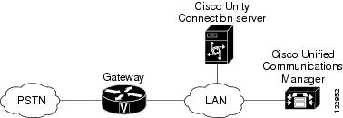
The Cisco Unified CallManager integration uses the LAN to connect Cisco Unity Connection and the phone system. The gateway provides connections to the PSTN. Figure 1 shows the connections.
Figure 1 Connections Between the Phone System and Cisco Unity Connection
Call Information
The phone system sends the following information with forwarded calls:
•The extension of the called party
•The extension of the calling party (for internal calls) or the phone number of the calling party (if it is an external call and the system uses caller ID)
•The reason for the forward (the extension is busy, does not answer, or is set to forward all calls)
Cisco Unity Connection uses this information to answer the call appropriately. For example, a call forwarded to Cisco Unity Connection is answered with the personal greeting of the user. If the phone system routes the call to Cisco Unity Connection without this information, Cisco Unity Connection answers with the opening greeting.
Integration Functionality
The Cisco Unified CallManager integration with Cisco Unity Connection provides the following features:
•Call forward to personal greeting
•Call forward to busy greeting
•Caller ID
•Easy message access (a user can retrieve messages without entering an ID; Cisco Unity Connection identifies a user based on the extension from which the call originated; a password may be required)
•Identified subscriber messaging (Cisco Unity Connection automatically identifies a user who leaves a message during a forwarded internal call, based on the extension from which the call originated)
•Message waiting indication (MWI)
The functionality of this integration may be affected by the issues described below.
Use of Cisco Unified Survivable Remote Site Telephony (SRST) Router
When a Cisco Unified Survivable Remote Site Telephony (SRST) router is part of the network and the Cisco Unified SRST router takes over call processing functions from Cisco Unified CallManager (for example, because the WAN link is down), phones at a branch office can continue to function. In this situation, however, the integration features have the following limitations:
•Call forward to busy greeting—When the Cisco Unified SRST router uses FXO/FXS connections to the PSTN and a call is forwarded from a branch office to Cisco Unity Connection, the busy greeting cannot play.
•Call forward to internal greeting—When the Cisco Unified SRST router uses FXO/FXS connections to the PSTN and a call is forwarded from a branch office to Cisco Unity Connection, the internal greeting cannot play. Because the PSTN provides the calling number of the FXO line, the caller is not identified as a user.
•Call transfers—Because an access code is needed to reach the PSTN, call transfers from Cisco Unity Connection to a branch office will fail.
•Identified user messaging—When the Cisco Unified SRST router uses FXO/FXS connections to the PSTN and a user at a branch office leaves a message or forwards a call, the user is not identified. The caller appears as an unidentified caller.
•Message waiting indication—MWIs are not updated on branch office phones, so MWIs will not correctly reflect when new messages arrive or when all messages have been listened to. We recommend resynchronizing MWIs after the WAN link is reestablished.
•Message notification—Because an access code is needed to reach the PSTN, message notifications from Cisco Unity Connection to a branch office will fail.
•Routing rules—When the Cisco Unified SRST router uses FXO/FXS connections to the PSTN and a call arrives from a branch office to Cisco Unity Connection (either a direct or forwarded call), routing rules will fail.
When the Cisco Unified SRST router uses PRI/BRI connections, the caller ID for calls from a branch office to Cisco Unity Connection may be the full number (exchange plus extension) provided by the PSTN and therefore may not match the extension of the Cisco Unity Connection user. If this is the case, you can let Cisco Unity Connection recognize the caller ID by using alternate extensions (for instructions, see the "Appendix: Using Alternate Extensions and MWIs" section).
Redirected Dialed Number Information Service (RDNIS) needs to be supported when using SRST.
For information on setting up Cisco Unified SRST routers, refer to the "Integrating Voice Mail with Cisco Unified SRST" section of the Cisco Unified SRST System Administrator Guide at http://www.cisco.com/univercd/cc/td/doc/product/software/ios122/122newft/122limit/122z/122zj15/index.htm.
Impact of Non-Delivery of RDNIS on Voice Mail Calls Routed via AAR
RDNIS needs to be supported when using Automated Alternate Routing (AAR).
AAR can route calls over the PSTN when the WAN is oversubscribed. However, when calls are rerouted over the PSTN, RDNIS can be affected. Incorrect RDNIS information can affect voice mail calls that are rerouted over the PSTN by AAR when Cisco Unity Connection is remote from its messaging clients. If the RDNIS information is not correct, the call will not reach the voice mail box of the dialed user but will instead receive the automated attendant prompt, and the caller might be asked to reenter the extension number of the party they wish to reach. This behavior is primarily an issue when the telephone carrier is unable to ensure RDNIS across the network. There are numerous reasons why the carrier might not be able to ensure that RDNIS is properly sent. Check with your carrier to determine whether it provides guaranteed RDNIS delivery end-to-end for your circuits. The alternative to using AAR for oversubscribed WANs is simply to let callers hear reorder tone in an oversubscribed condition.
Integrations with Multiple Phone Systems
Cisco Unity Connection can be integrated with multiple phone systems at one time. For information on and instructions for integrating Cisco Unity Connection with multiple phone systems, refer to the Multiple Phone System Integration Guide at http://www.cisco.com/en/US/products/ps6509/products_installation_and_configuration_guides_list.html.
Planning How the Voice Messaging Ports Will Be Used by Cisco Unity Connection
Before programming the phone system, you need to plan how the voice messaging ports will be used by Cisco Unity Connection. The following considerations will affect the programming for the phone system (for example, setting up the hunt group or call forwarding for the voice messaging ports):
•The number of voice messaging ports installed.
•The number of voice messaging ports that will answer calls.
•The number of voice messaging ports that will only dial out, for example, to send message notification, to set message waiting indicators (MWIs), and to make telephone record and playback (TRAP) connections.
The following table describes the voice messaging port settings in Cisco Unity Connection that can be set on Telephony Integrations > Port of Cisco Unity Connection Administration.
The Number of Voice Messaging Ports to Install
The number of voice messaging ports to install depends on numerous factors, including:
•The number of calls Cisco Unity Connection will answer when call traffic is at its peak.
•The expected length of each message that callers will record and that users will listen to.
•The number of users.
•The number of ports that will be set to dial out only.
•The number of calls made for message notification.
•The number of MWIs that will be activated when call traffic is at its peak.
•The number of TRAP connections needed when call traffic is at its peak. (TRAP connections are used by Cisco Unity Connection web applications to play back and record over the phone.)
•The number of calls that will use the automated attendant and call handlers when call traffic is at its peak.
It is best to install only the number of voice messaging ports that are needed so that system resources are not allocated to unused ports.
The Number of Voice Messaging Ports That Will Answer Calls
The calls that the voice messaging ports answer can be incoming calls from unidentified callers or from users. Typically, the voice messaging ports that answer calls are the busiest.
You can set voice messaging ports to both answer calls and to dial out (for example, to send message notifications). However, when the voice messaging ports perform more than one function and are very active (for example, answering many calls), the other functions may be delayed until the voice messaging port is free (for example, message notifications cannot be sent until there are fewer calls to answer). For best performance, dedicate certain voice messaging ports for only answering incoming calls, and dedicate other ports for only dialing out. Separating these port functions eliminates the possibility of a collision, in which an incoming call arrives on a port at the same time that Cisco Unity Connection takes the port off-hook to dial out.
The Number of Voice Messaging Ports That Will Only Dial Out, and Not Answer Calls
Ports that will only dial out and will not answer calls can do one or more of the following:
•Notify users by phone, pager, or e-mail of messages that have arrived.
•Turn MWIs on and off for user extensions.
•Make a TRAP connection so that users can use the phone as a recording and playback device in Cisco Unity Connection web applications.
Typically, these voice messaging ports are the least busy ports.
Caution In programming the phone system, do not send calls to voice messaging ports in Cisco Unity Connection that cannot answer calls (voice messaging ports that are not set to Answer Calls). For example, if a voice messaging port is set only to Perform Message Notifications, do not send calls to it.
Preparing for Programming the Phone System
Record your decisions about the voice messaging ports to guide you in programming the phone system.
Programming the Cisco Unified CallManager Phone System
Do the following procedures in the order given.
Note There must be a calling search space that is used by all user phones (directory numbers). Otherwise, the integration will not function correctly. For instructions on setting up a calling search space and assigning user phones to it, refer to the Cisco Unified CallManager Help.
To Create the SIP Trunk Security Profile
Step 1 In Cisco Unified CallManager Administration, on the System menu, click Security Profile > SIP Trunk Security Profile.
Step 2 On the Find and List SIP Trunk Security Profiles page, click Add New.
Step 3 On the SIP Trunk Security Profile Configuration page, under SIP Trunk Security Profile Information, enter the following settings.
Step 4 Click Save.
To Create the SIP Profile
Step 1 On the Device menu, click Device Settings > SIP Profile.
Step 2 On the Find and List SIP Profiles page, click Add New.
Step 3 On the SIP Profile Configuration page, enter the following settings.
Step 4 Click Save.
To Create the SIP Trunk
Step 1 On the Device menu, click Trunk.
Step 2 On the Find and List Trunks page, click Add New.
Step 3 On the Trunk Configuration page, in the Trunk Type field, click SIP Trunk.
Step 4 In the Device Protocol field, click SIP and click Next.
Step 5 Under Device Information, enter the following settings.
Step 6 Under Outbound Calls, check the Redirecting Diversion Header Delivery - Outbound check box.
Step 7 Under SIP Information, enter the following settings.
Table 5 Settings for SIP Information on the Trunk Configuration Page
Field SettingDestination Address
Enter the IP address of the Cisco Unity Connection SIP port to which Cisco Unified CallManager will connect.
Destination Port
We recommend that you accept the default of 5060.
SIP Trunk Security Profile
Click the name of the SIP trunk security profile that you created in the "To Create the SIP Trunk Security Profile" procedure. For example, click "Cisco Unity Connection SIP Trunk Security Profile."
Rerouting Calling Search Space
Click the name of the calling search space that is used by user phones.
Out-of-Dialog Refer Calling Search Space
Click the name of the calling search space that is used by user phones.
SIP Profile
Click the name of the SIP profile that you created in the "To Create the SIP Profile" procedure. For example, click "Cisco Unity Connection SIP Profile."
Step 8 Adjust any other settings that are needed for your site.
Step 9 Click Save.
To Create a Route Pattern
Step 1 On the Call Routing menu, click Route/Hunt > Route Pattern.
Step 2 On the File and List Route Patterns page, click Add New.
Step 3 On the Route Pattern Configuration page, enter the following settings.
Table 6 Settings for the Route Pattern Configuration Page
Field SettingRoute Pattern
Enter the voice mail pilot number for Cisco Unity Connection.
Gateway/Route List
Click the name of the SIP trunk that you created in the "To Create the SIP Trunk" procedure. For example, click "Connection_SIP_Trunk."
Step 4 Click Save.
To Create the Voice Mail Pilot
Step 1 On the Voice Mail menu, click Voice Mail Pilot.
Step 2 On the Find and List Voice Mail Pilots page, click Add New.
Step 3 On the Voice Mail Pilot Configuration page, enter the following voice mail pilot number settings.
Table 7 Settings for the Voice Mail Pilot Configuration Page
Field SettingVoice Mail Pilot Number
Enter the voice mail pilot number that users will dial to listen to their voice messages. This number must match the route pattern that you entered in the "To Create a Route Pattern" procedure.
Calling Search Space
Click the calling search space that includes partitions containing the user phones and the partition that you set up for the voice mail pilot number.
Description
Enter Connection Pilot or another description.
Make This the Default Voice Mail Pilot for the System
Check this check box. When this check box is checked, this voice mail pilot number replaces the current default pilot number.
Step 4 Click Save.
To Create the Voice Mail Profile
Step 1 On the Voice Mail menu, click Voice Mail Profile.
Step 2 On the Find and List Voice Mail Profiles page, click Add New.
Step 3 On the Voice Mail Profile Configuration page, enter the following voice mail profile settings.
Table 8 Settings for the Voice Mail Profile Configuration Page
Field SettingVoice Mail Profile Name
Enter Connection Profile or another name to identify the voice mail profile.
Description
Enter Profile for Cisco Unity Connection or another description.
Voice Mail Pilot
Click the voice mail pilot number that you defined in the "To Create the Voice Mail Pilot" procedure.
Voice Mail Box Mask
When multitenant services are not enabled on Cisco Unified CallManager, leave this field blank.
When multitenant services are enabled, each tenant uses its own voice mail profile and must create a mask to identify the extensions (directory numbers) in each partition that is shared with other tenants. For example, one tenant can use a mask 972813XXXX, while another tenant can use the mask 214333XXXX. It is also necessary to set up translation patterns for MWIs.
Make This the Default Voice Mail Profile for the System
Check this check box to make this voice mail profile the default.
When this check box is checked, this voice mail profile replaces the current default voice mail profile.
Step 4 Click Save.
Do the following two procedures only if you want to set up SIP Digest authentication.
If you do not want to set up SIP digest authentication, continue to the "Creating a New Integration with the Cisco Unified CallManager Phone System" procedure.
(Optional) To Set Up SIP Digest Authentication
Step 1 On the System menu, click Security Profile > SIP Trunk Security Profile.
Step 2 On the Find and List SIP Trunk Security Profiles page, click the SIP trunk security profile that you created in the "To Create the SIP Trunk Security Profile" procedure.
Step 3 On the SIP Trunk Security Profile Configuration page, check the Enable Digest Authentication check box.
Step 4 Click Save.
(Optional) To Create the Application User
Step 1 On the User Management menu, click Application User.
Step 2 On the Find and List Application Users page, click Add New.
Step 3 On the Application User Configuration page, enter the following settings.
Step 4 Click Save.
Creating a New Integration with the Cisco Unified CallManager Phone System
After ensuring that the Cisco Unified CallManager phone system and Cisco Unity Connection are ready for the integration, do the following procedures to set up the integration and to enter the port settings.
To Create an Integration
Step 1 Log on to Cisco Unity Connection Administration.
Step 2 In Cisco Unity Connection Administration, expand Telephony Integrations, then click Phone System.
Step 3 On the Search Phone Systems page, on the Phone System menu, click New Phone System. The Phone System Integration Wizard appears.
Step 4 On the Select Phone System Manufacturer page, in the Manufacturer field, click Cisco Systems and click Next.
Step 5 On the Select Phone System Model page, in the Model field, click CallManager and click Next.
Step 6 On the Set Up Phone System page, in the Phone System Name field, accept the default name or enter the descriptive name that you want, and click Next.
Step 7 On the Select Port Group Template page, in the Port Group Template field, click SIP - Session Initiation Protocol and click Next.
Step 8 On the Set Up Port Group page, enter the following settings and click Next.
Step 9 On the Confirm Phone System Settings page, confirm the settings that you have entered and click Finish.
Step 10 On the Phone System Creation Summary page, click Close.
Step 11 In Cisco Unity Connection Administration, expand Telephony Integrations, then click Port Group.
Step 12 On the Search Port Groups page, click the display name of the port group that you created for the Cisco Unified CallManager integration.
Note By default, the display name for a port group is composed of the phone system display name followed by an incrementing number.
Step 13 On the Port Group Basics page, on the Edit menu, click Servers.
Step 14 On the Edit Servers page, do the following substeps if there are secondary Cisco Unified CallManager servers. Otherwise, continue to Step 15.
a. Under SIP Proxy Servers, click Add.
b. Enter the following settings for the secondary Cisco Unified CallManager server and click Save.
Note You can click Ping to verify the IP address (or host name) of the Cisco Unified CallManager server.
c. Repeat Step 14a. and Step 14b. for all remaining secondary Cisco Unified CallManager servers in the cluster.
Step 15 In Cisco Unity Connection Administration, expand Telephony Integrations, then click Port.
Step 16 On the Search Ports page, click the display name of the first voice messaging port that you created for this phone system integration.
Note By default, the display names for the voice messaging ports are composed of the port group display name followed by incrementing numbers.
Step 17 On the Port Basics page, enter the following settings. The fields in the following table are the ones that you can change.
Step 18 Click Save.
Step 19 Click Next.
Step 20 Repeat Step 17 through Step 19 for all remaining voice messaging ports for the phone system.
Step 21 If another phone system integration exists, in Cisco Unity Connection Administration, expand Telephony Integrations, then click Trunk. Otherwise, skip to Step 25.
Step 22 On the Search Phone System Trunks page, on the Phone System Trunk menu, click New Phone System Trunk.
Step 23 On the New Phone System Trunk page, enter the following settings for the phone system trunk and click Save.
Step 24 Repeat Step 22 and Step 23 for all remaining phone system trunks that you want to create.
Step 25 If prompted to restart Cisco Unity Connection, in the Windows task bar, right-click the Cisco Unity Connection icon and click Restart > Voice Processing Server Role.
Step 26 When prompted to confirm stopping the Voice Processing server role, click Yes.
Step 27 In Cisco Unity Connection Administration, in the Related Links drop-down list, click Check Telephony Configuration and click Go to confirm the phone system integration settings.
If the test is not successful, the Task Execution Results displays one or more messages with troubleshooting steps. After correcting the problems, test the connection again.
Step 28 In the Task Execution Results window, click Close.
Step 29 Log off Cisco Unity Connection Administration.
Testing the Integration
To test whether Cisco Unity Connection and the phone system are integrated correctly, do the following procedures in the order listed.
If any of the steps indicate a failure, refer to the following documentation as applicable:
•The installation guide for the phone system.
•The setup information earlier in this guide.
To Set Up the Test Configuration
Step 1 Set up two test extensions (Phone 1 and Phone 2) on the same phone system that Cisco Unity Connection is connected to.
Step 2 Set Phone 1 to forward calls to the Cisco Unity Connection pilot number when calls are not answered.
Caution The phone system must forward calls to the Cisco Unity Connection pilot number in no fewer than four rings. Otherwise, the test may fail.
Step 3 To create a test user for testing, in Cisco Unity Connection Administration, expand Users, then click Users.
Step 4 On the Search Users page, on the User menu, click New User.
Step 5 On the New User page, enter the following settings.
Step 6 Click Save.
Step 7 On the Edit User Basics page, in the Voice Name field, record a voice name for the test user.
Step 8 In the Phone System field, confirm that the phone system selected is the phone system that Phone 1 is connected to.
Step 9 Uncheck the Set for Self-enrollment at Next Login check box.
Step 10 Click Save.
Step 11 On the Edit menu, click Message Waiting Indicators.
Step 12 On the Message Waiting Indicators page, click the message waiting indicator. If no message waiting indication is in the table, click Add New.
Step 13 On the Edit Message Waiting Indicator page, enter the following settings.
Step 14 Click Save.
Step 15 On the Edit menu, click Transfer Options.
Step 16 On the Transfer Options page, click the active option.
Step 17 On the Edit Transfer Option page, under Transfer Action, click the Extension option and enter the extension of Phone 1.
Step 18 In the Transfer Type field, click Release to Switch.
Step 19 Click Save.
Step 20 Minimize the Cisco Unity Connection Administration window.
Do not close the Cisco Unity Connection Administration window because you will use it again in a later procedure.
Step 21 On the Cisco Unity Connection desktop, double-click the Tools Depot icon.
Step 22 In the left pane of the Tools Depot window, expand Switch Integration Tools, then double-click Port Status Monitor. The Port Status Monitor window appears.
Step 23 On the Ports menu, click Start All, and arrange the port monitors so that you can notice which port will handle the calls that you will make.
To Test an External Call with Release Transfer
Step 1 From Phone 2, enter the access code necessary to get an outside line, then enter the number outside callers use to dial directly to Cisco Unity Connection.
Step 2 In the Port Status Monitor, note which port handles this call.
Step 3 When you hear the opening greeting, enter the extension for Phone 1. Hearing the opening greeting means that the port is configured correctly.
Step 4 Confirm that Phone 1 rings and that you hear a ringback tone on Phone 2. Hearing a ringback tone means that Cisco Unity Connection correctly released the call and transferred it to Phone 1.
Step 5 Leaving Phone 1 unanswered, confirm that the state of the port handling the call changes to "Idle." This state means that release transfer is successful.
Step 6 Confirm that, after the number of rings that the phone system is set to wait, the call is forwarded to Cisco Unity Connection and that you hear the greeting for the test user. Hearing the greeting means that the phone system forwarded the unanswered call and the call-forward information to Cisco Unity Connection, which correctly interpreted the information.
Step 7 On the Port Status Monitor, note which port handles this call.
Step 8 Leave a message for the test user and hang up Phone 2.
Step 9 In the Port Status Monitor, confirm that the state of the port handling the call changes to "Idle." This state means that the port was successfully released when the call ended.
Step 10 Confirm that the MWI on Phone 1 is activated. The activated MWI means that the phone system and Cisco Unity Connection are successfully integrated for turning on MWIs.
To Test Listening to Messages
Step 1 From Phone 1, enter the internal pilot number for Cisco Unity Connection.
Step 2 When asked for your password, enter the password for the test user. Hearing the request for your password means that the phone system sent the necessary call information to Cisco Unity Connection, which correctly interpreted the information.
Step 3 Confirm that you hear the recorded voice name for the test user (if you did not record a voice name for the test user, you will hear the extension number for Phone 1). Hearing the voice name means that Cisco Unity Connection correctly identified the user by the extension.
Step 4 Listen to the message.
Step 5 After listening to the message, delete the message.
Step 6 Confirm that the MWI on Phone 1 is deactivated. The deactivated MWI means that the phone system and Cisco Unity Connection are successfully integrated for turning off MWIs.
Step 7 Hang up Phone 1.
Step 8 On the Port Status Monitor, confirm that the state of the port handling the call changes to "Idle." This state means that the port was successfully released when the call ended.
To Set Up Supervised Transfer on Cisco Unity Connection
Step 1 In Cisco Unity Connection Administration, on the Edit Transfer Option page for the test user, in the Transfer Type field, click Supervise Transfer.
Step 2 In the Rings to Wait For field, enter 3.
Step 3 Click Save.
Step 4 Minimize the Cisco Unity Connection Administration window.
Do not close the Cisco Unity Connection Administration window because you will use it again in a later procedure.
To Test Supervised Transfer
Step 1 From Phone 2, enter the access code necessary to get an outside line, then enter the number outside callers use to dial directly to Cisco Unity Connection.
Step 2 On the Port Status Monitor, note which port handles this call.
Step 3 When you hear the opening greeting, enter the extension for Phone 1. Hearing the opening greeting means that the port is configured correctly.
Step 4 Confirm that Phone 1 rings and that you do not hear a ringback tone on Phone 2. Instead, you should hear the indication your phone system uses to mean that the call is on hold (for example, music).
Step 5 Leaving Phone 1 unanswered, confirm that the state of the port handling the call remains "Busy." This state and hearing an indication that you are on hold mean that Cisco Unity Connection is supervising the transfer.
Step 6 Confirm that, after three rings, you hear the greeting for the test user. Hearing the greeting means that Cisco Unity Connection successfully recalled the supervised-transfer call.
Step 7 During the greeting, hang up Phone 2.
Step 8 On the Port Status Monitor, confirm that the state of the port handling the call changes to "Idle." This state means that the port was successfully released when the call ended.
Step 9 Exit the Port Status Monitor.
To Delete the Test User
Step 1 In Cisco Unity Connection Administration, expand Users, then click Users.
Step 2 On the Search Users page, check the check box to the left of the test user.
Step 3 Click Delete Selected.
(Multiple Integrations Only) Adding New User Templates
When you create the first phone system integration, this phone system is automatically selected in the default user template. The users that you add after creating this phone system integration will be assigned to this phone system by default.
However, for each additional phone system integration that you create, you must add the applicable new user templates that will assign users to the new phone system. You must add the new templates before you add new users who will be assigned to the new phone system.
For details on adding new user templates, refer to the "Adding, Changing, or Deleting an Account Template" chapter in the Cisco Unity Connection User Moves, Adds, and Changes Guide at http://www.cisco.com/en/US/products/ps6509/prod_maintenance_guides_list.html.
For details on selecting a user template when adding a new user, refer to the applicable chapter for adding user accounts in the Cisco Unity Connection User Moves, Adds, and Changes Guide at http://www.cisco.com/en/US/products/ps6509/prod_maintenance_guides_list.html.
Changing the Number of Voice Messaging Ports
If you are adding voice messaging ports, do the "To Add Voice Messaging Ports in Cisco Unity Connection Administration" procedure.
If you are deleting voice messaging ports, do the "To Delete Voice Messaging Ports in Cisco Unity Connection Administration" procedure.
To Add Voice Messaging Ports in Cisco Unity Connection Administration
Step 1 If the Cisco Unity Connection license does not enable the additional voice messaging ports you added, see your sales representative to request the applicable license.
Step 2 When you have the license, log on to Cisco Unity Connection Administration.
Step 3 In Cisco Unity Connection Administration, expand System Settings, then click Licenses.
Step 4 On the License page, on the License menu, click Add New License.
Step 5 On the Add New License page, click Browse.
Step 6 In the Choose File dialog box, browse to license file and click Open.
Step 7 On the Add New License page, click Add.
Step 8 On the Licenses page, check the check box for the license file that you added in Step 7 and click Install Selected.
Step 9 In Cisco Unity Connection Administration, expand Telephony Integrations, then click Port.
Step 10 On the Search Ports page, under Port Search Results, click Add New.
Step 11 On the New Port page, enter the applicable settings and click Save.
Caution Make sure that there are an appropriate number of ports set to answer calls and an appropriate number of ports set to dial out. Otherwise, the integration will not function correctly. For details, see to the "Planning How the Voice Messaging Ports Will be Used by Cisco Unity Connection" section.
Step 12 If prompted to restart Cisco Unity Connection, in the Windows task bar, right-click the Cisco Unity Connection icon and click Restart > Voice Processing Server Role.
Step 13 When prompted to confirm stopping the Voice Processing server role, click Yes.
Step 14 Log off Cisco Unity Connection Administration.
To Delete Voice Messaging Ports in Cisco Unity Connection Administration
Step 1 Log on to the Cisco Unity Connection Administration.
Step 2 Go to the Telephony Integrations > Port page.
Step 3 Under Port Search Results, check the check boxes next to the voice messaging ports that you want to delete.
Step 4 Click Delete Selected.
Step 5 For the remaining voice messaging ports in the port group, change the settings as necessary so that there are an appropriate number of voice messaging ports set to answer calls and an appropriate number of voice messaging ports set to dial out.
Step 6 In the Windows task bar, right-click the Cisco Unity Connection icon and click Restart > Voice Processing Server Role.
Step 7 When prompted to confirm stopping the Voice Processing server role, click Yes.
Step 8 In Cisco Unity Connection Administration, in the Related Links drop-down list, click Check Telephony Configuration and click Go to confirm the phone system integration settings.
If the test is not successful, the Task Execution Results displays one or more messages with troubleshooting steps. After correcting the problems, test the connection again.
Step 9 In the Task Execution Results window, click Close.
Step 10 Log off the Cisco Unity Connection Administration.
Adding a Cisco Unified CallManager Express Server to a Cisco Unified CallManager Phone System Integration
Cisco Unity Connection can integrate a Cisco Unified CallManager phone system integration that has a port group of Cisco Unified CallManager servers and a port group of a Cisco Unified CallManager Express server. This configuration is typically used to ensure call processing functionality at a branch office when the WAN link is down.
There are, however, the following considerations:
•The version of Cisco Unified CallManager Express and the version of the Cisco Unity-CM TSP must be a supported combination in the Compatibility Matrix: Cisco Unity Connection, the Cisco Unity-CM TSP, Cisco Unified CallManager, and Cisco Unified CallManager Express at http://www.cisco.com/univercd/cc/td/doc/product/voice/c_unity/cmptblty/tspmtrx.htm.
•The Cisco Unified CallManager phone system integration is typically already created before adding the Cisco Unified CallManager Express server.
•The Cisco Unified CallManager Express server is in its own port group, which is separate from the port group for the Cisco Unified CallManager servers.
•The Cisco Unified CallManager Express port group has its own voice messaging ports that connect only to the Cisco Unified CallManager Express server.
To add a Cisco Unified CallManager Express server to a Cisco Unified CallManager phone system integration, do the following procedure.
To Add a Cisco Unified CallManager Express Server to a Cisco Unified CallManager Phone System Integration
Step 1 Log on to Cisco Unity Connection Administration.
Step 2 In Cisco Unity Connection Administration, expand Telephony Integrations, then click Port Group.
Step 3 On the Search Port Groups page, under Port Group Search Results, click Add New.
Step 4 On the New Port Group page, enter the following settings.
Step 5 Click Save.
Step 6 On the Port Group Basics page, on the Edit menu, click Servers.
Step 7 On the Edit Servers page, in the Server Type field, click Cisco Unified CallManager Express.
Note You can click Ping to verify the IP address of the Cisco Unified CallManager Express server.
Step 8 Click Save.
Step 9 On the Edit menu, click Advanced Settings.
Step 10 On the Edit Advanced Settings page, in the Delay Before Opening Greeting field, enter 1000 and click Save.
Step 11 In Cisco Unity Connection Administration, expand Telephony Integrations, then click Port.
Step 12 On the Search Ports page, under Port Search Results, click Add New.
Step 13 On the New Port page, enter the following settings.
Table 17 Settings for the New Port Page
Field SettingNumber of Ports
Enter the number of voice messaging ports that you want to create on Cisco Unity Connection for connecting to the Cisco Unified CallManager Express server.
Phone System
Click the display name of the Cisco Unified CallManager phone system integration.
Port Group
Click the display name of the port group that you created for the Cisco Unified CallManager Express server in Step 5.
Step 14 Click Save.
Step 15 On the Search Ports page, click the display name of the first voice messaging port that you created for the Cisco Unified CallManager Express port group.
Note By default, the display names for the voice messaging ports are composed of the port group display name followed by incrementing numbers.
Step 16 On the Port Basics page, set the voice messaging port settings as applicable. The fields in the following table are the ones that you can change.
Step 17 Click Save.
Step 18 Click Next.
Step 19 Repeat Step 16 through Step 18 for all remaining voice messaging ports in the Cisco Unified CallManager Express port group.
Step 20 In the Windows task bar, right-click the Cisco Unity Connection icon and click Restart > Voice Processing Server Role.
Step 21 When prompted to confirm stopping the Voice Processing server role, click Yes.
Step 22 In Cisco Unity Connection Administration, in the Related Links drop-down list, click Test Port Group and click Go to confirm the Cisco Unified CallManager port group settings.
Step 23 When prompted that the test will terminate call in progress, click OK.
If the test is not successful, the Task Execution Results displays one or more messages with troubleshooting steps. After correcting the problems, test the connection again.
Step 24 In the Task Execution Results window, click Close.
Step 25 Log off Cisco Unity Connection Administration.
Appendix: Documentation and Technical Assistance
Conventions
The Cisco Unified CallManager 5.0 SIP Trunk Integration Guide for Cisco Unity Connection 1.1 uses the following conventions.
The Cisco Unified CallManager 5.0 SIP Trunk Integration Guide for Cisco Unity Connection 1.1 also uses the following conventions:
Note Means reader take note. Notes contain helpful suggestions or references to material not covered in the document.
Caution Means reader be careful. In this situation, you might do something that could result in equipment damage or loss of data.
For descriptions and URLs of Cisco Unity Connection documentation on Cisco.com, see the About Cisco Unity Connection Documentation. The document is shipped with Cisco Unity Connection and is available at http://www.cisco.com/en/US/products/ps6509/products_documentation_roadmaps_list.html.
Obtaining Documentation
Cisco documentation and additional literature are available on Cisco.com. This section explains the product documentation resources that Cisco offers.
Cisco.com
You can access the most current Cisco documentation at this URL:
http://www.cisco.com/techsupport
You can access the Cisco website at this URL:
You can access international Cisco websites at this URL:
http://www.cisco.com/public/countries_languages.shtml
Product Documentation DVD
The Product Documentation DVD is a library of technical product documentation on a portable medium. The DVD enables you to access installation, configuration, and command guides for Cisco hardware and software products. With the DVD, you have access to the HTML documentation and some of the PDF files found on the Cisco website.
The Product Documentation DVD is created and released regularly. DVDs are available singly or by subscription. Registered Cisco.com users can order a Product Documentation DVD (product number DOC-DOCDVD= or DOC-DOCDVD=SUB) from Cisco Marketplace at the Product Documentation Store at this URL:
http://www.cisco.com/go/marketplace/docstore
Ordering Documentation
You must be a registered Cisco.com user to access Cisco Marketplace. Registered users may order Cisco documentation at the Product Documentation Store at this URL:
http://www.cisco.com/go/marketplace/docstore
If you do not have a user ID or password, you can register at this URL:
http://tools.cisco.com/RPF/register/register.do
Documentation Feedback
You can provide feedback about Cisco technical documentation on the Cisco Support site area by entering your comments in the feedback form available in every online document.
Cisco Product Security Overview
Cisco provides a free online Security Vulnerability Policy portal at this URL:
http://www.cisco.com/en/US/products/products_security_vulnerability_policy.html
From this site, you will find information about how to do the following:
•Report security vulnerabilities in Cisco products
•Obtain assistance with security incidents that involve Cisco products
•Register to receive security information from Cisco
A current list of security advisories, security notices, and security responses for Cisco products is available at this URL:
To see security advisories, security notices, and security responses as they are updated in real time, you can subscribe to the Product Security Incident Response Team Really Simple Syndication (PSIRT RSS) feed. Information about how to subscribe to the PSIRT RSS feed is found at this URL:
http://www.cisco.com/en/US/products/products_psirt_rss_feed.html
Reporting Security Problems in Cisco Products
Cisco is committed to delivering secure products. We test our products internally before we release them, and we strive to correct all vulnerabilities quickly. If you think that you have identified a vulnerability in a Cisco product, contact PSIRT:
•For emergencies only — security-alert@cisco.com
An emergency is either a condition in which a system is under active attack or a condition for which a severe and urgent security vulnerability should be reported. All other conditions are considered nonemergencies.
•For nonemergencies — psirt@cisco.com
In an emergency, you can also reach PSIRT by telephone:
•1 877 228-7302
•1 408 525-6532
Tip We encourage you to use Pretty Good Privacy (PGP) or a compatible product (for example, GnuPG) to encrypt any sensitive information that you send to Cisco. PSIRT can work with information that has been encrypted with PGP versions 2.x through 9.x.
Never use a revoked encryption key or an expired encryption key. The correct public key to use in your correspondence with PSIRT is the one linked in the Contact Summary section of the Security Vulnerability Policy page at this URL:
http://www.cisco.com/en/US/products/products_security_vulnerability_policy.html
The link on this page has the current PGP key ID in use.
If you do not have or use PGP, contact PSIRT to find other means of encrypting the data before sending any sensitive material.
Product Alerts and Field Notices
Modifications to or updates about Cisco products are announced in the Product Field Notice Summary. Registered users can sign up to receive email notifications. Alternately, you can subscribe to the Field Notice RSS Feed. For more information, visit:
http://www.cisco.com/en/US/support/tsd_products_field_notice_summary.html
Obtaining Technical Assistance
Cisco Technical Support provides 24-hour-a-day award-winning technical assistance. The Cisco Support website on Cisco.com features extensive online support resources. In addition, if you have a valid Cisco service contract, Cisco Technical Assistance Center (TAC) engineers provide telephone support. If you do not have a valid Cisco service contract, contact your reseller.
Cisco Support Website
The Cisco Support website provides online documents and tools for troubleshooting and resolving technical issues with Cisco products and technologies. The website is available 24 hours a day at this URL:
http://www.cisco.com/en/US/support/index.html
Access to all tools on the Cisco Support website requires a Cisco.com user ID and password. If you have a valid service contract but do not have a user ID or password, you can register at this URL:
http://tools.cisco.com/RPF/register/register.do
Note Before you submit a request for service online or by phone, use the Cisco Product Identification Tool to locate your product serial number. You can access this tool from the Cisco Support website by clicking the Get Tools & Resources link, clicking the All Tools (A-Z) tab, and then choosing Cisco Product Identification Tool from the alphabetical list. This tool offers three search options: by product ID or model name; by tree view; or, for certain products, by copying and pasting show command output. Search results show an illustration of your product with the serial number label location highlighted. Locate the serial number label on your product and record the information before placing a service call.
Tip Displaying and Searching on Cisco.com
If you suspect that the browser is not refreshing a web page, force the browser to update the web page by holding down the Ctrl key while pressing F5.
To find technical information, narrow your search to look in technical documentation, not the entire Cisco.com website. After using the Search box on the Cisco.com home page, click the Advanced Search link next to the Search box on the resulting page and then click the Technical Support & Documentation radio button.
To provide feedback about the Cisco.com website or a particular technical document, click Contacts & Feedback at the top of any Cisco.com web page.
Submitting a Service Request
Using the online TAC Service Request Tool is the fastest way to open S3 and S4 service requests. (S3 and S4 service requests are those in which your network is minimally impaired or for which you require product information.) After you describe your situation, the TAC Service Request Tool provides recommended solutions. If your issue is not resolved using the recommended resources, your service request is assigned to a Cisco engineer. The TAC Service Request Tool is located at this URL:
http://www.cisco.com/techsupport/servicerequest
For S1 or S2 service requests, or if you do not have Internet access, contact the Cisco TAC by telephone. (S1 or S2 service requests are those in which your production network is down or severely degraded.) Cisco engineers are assigned immediately to S1 and S2 service requests to help keep your business operations running smoothly.
To open a service request by telephone, use one of the following numbers:
Asia-Pacific: +61 2 8446 7411
Australia: 1 800 805 227
EMEA: +32 2 704 55 55
USA: 1 800 553 2447For a complete list of Cisco TAC contacts, go to this URL:
http://www.cisco.com/techsupport/contacts
Definitions of Service Request Severity
To ensure that all service requests are reported in a standard format, Cisco has established severity definitions.
Severity 1 (S1)—An existing network is "down" or there is a critical impact to your business operations. You and Cisco will commit all necessary resources around the clock to resolve the situation.
Severity 2 (S2)—Operation of an existing network is severely degraded, or significant aspects of your business operations are negatively affected by inadequate performance of Cisco products. You and Cisco will commit full-time resources during normal business hours to resolve the situation.
Severity 3 (S3)—Operational performance of the network is impaired while most business operations remain functional. You and Cisco will commit resources during normal business hours to restore service to satisfactory levels.
Severity 4 (S4)—You require information or assistance with Cisco product capabilities, installation, or configuration. There is little or no effect on your business operations.
Obtaining Additional Publications and Information
Information about Cisco products, technologies, and network solutions is available from various online and printed sources.
•The Cisco Online Subscription Center is the website where you can sign up for a variety of Cisco e-mail newsletters and other communications. Create a profile and then select the subscriptions that you would like to receive. To visit the Cisco Online Subscription Center, go to this URL:
http://www.cisco.com/offer/subscribe
•The Cisco Product Quick Reference Guide is a handy, compact reference tool that includes brief product overviews, key features, sample part numbers, and abbreviated technical specifications for many Cisco products that are sold through channel partners. It is updated twice a year and includes the latest Cisco channel product offerings. To order and find out more about the Cisco Product Quick Reference Guide, go to this URL:
•Cisco Marketplace provides a variety of Cisco books, reference guides, documentation, and logo merchandise. Visit Cisco Marketplace, the company store, at this URL:
http://www.cisco.com/go/marketplace/
•Cisco Press publishes a wide range of general networking, training, and certification titles. Both new and experienced users will benefit from these publications. For current Cisco Press titles and other information, go to Cisco Press at this URL:
•Internet Protocol Journal is a quarterly journal published by Cisco for engineering professionals involved in designing, developing, and operating public and private internets and intranets. You can access the Internet Protocol Journal at this URL:
•Networking products offered by Cisco, as well as customer support services, can be obtained at this URL:
http://www.cisco.com/en/US/products/index.html
•Networking Professionals Connection is an interactive website where networking professionals share questions, suggestions, and information about networking products and technologies with Cisco experts and other networking professionals. Join a discussion at this URL:
http://www.cisco.com/discuss/networking
•"What's New in Cisco Documentation" is an online publication that provides information about the latest documentation releases for Cisco products. Updated monthly, this online publication is organized by product category to direct you quickly to the documentation for your products. You can view the latest release of "What's New in Cisco Documentation" at this URL:
http://www.cisco.com/univercd/cc/td/doc/abtunicd/136957.htm
•World-class networking training is available from Cisco. You can view current offerings at this URL:
http://www.cisco.com/en/US/learning/index.html
Any Internet Protocol (IP) addresses used in this document are not intended to be actual addresses. Any examples, command display output, and figures included in the document are shown for illustrative purposes only. Any use of actual IP addresses in illustrative content is unintentional and coincidental.
© 2006 Cisco Systems, Inc. All rights reserved.