-
Cisco CDA Visual Quality Experience Application User Guide, Release 2.1
-
Preface
-
Introduction to Cisco CDA Visual Quality Experience Application
-
Getting Started with the VQE Startup Configuration Utility
-
Using the VQE Channel Provisioning Tool
-
Using the VQE-S Application Monitoring Tool
-
Troubleshooting VQE Software Components
-
Configuring VQE-S
-
Using Net-SNMP
-
VQE System Messages
-
Manual Initial VQE System Configuration
-
Configuring DHCP and DNS Servers for VCDS
-
 Feedback
Table Of Contents
Manual Initial VQE System Configuration
Setting Up a Cisco CDE110 That Hosts VQE-S
Prerequisites for a Cisco CDE110 That Hosts VQE-S
Setting Up SSL Certificates for VQE-S
Configuring the Linux Operating System for VQE-S
Configuring Static Routes for VQE-S
Configuring Default ECMP Routes for CDE110 Ethernet Interfaces (VQE-S Host)
Configuring a Static Route for a CDE110 Management Interface (VQE-S Host)
Configuring Static Routes for Feedback Targets on the Attached Router
Multicast Load Balancer and the Management Network
Enabling the VQE STUN Server (Optional)
Configuring XML-RPC Port Numbers
Configuring Net-SNMP (Optional)
Ensuring That Only Trusted HTTPS Clients Can Push an SDP File
Starting VQE-S System Services and Verifying Status
Starting the VQE-S Processes and Verifying Status
Restarting the System and Verifying System and VQE-S Status
Setting Up a Cisco CDE110 That Hosts VCPT and VQE Client Channel Configuration Delivery Server
Prerequisites for a Cisco CDE110 That Hosts VCPT
Setting Up SSL Certificates for VCPT
Configuring the Linux Operating System for VCPT and VQE Client Channel Configuration Delivery Server
Configuring a Static Route for a CDE110 Management Interface (VCPT Host)
Configuring Net-SNMP (Optional)
Starting VCPT System Services and Verifying Status
Starting the VQE Client Channel Configuration Delivery Server Process and Verifying Status
Manual Initial VQE System Configuration
This appendix explains how to perform manual initial configuration on the CDE110 that hosts VQE-S and on the CDE110 that hosts VCPT and VQE Client Channel Configuration Delivery Server (VCDS).
The alternative to manual configuration is to use the Cisco VQE Startup Configuration Utility. For information on using the utility, see the "Getting Started Using the VQE Startup Configuration Utility" section on page 2-12.
Note
Cisco recommends that you use the VQE Startup Configuration Utility rather than try to do the initial configuration manually because the utility simplifies your work and is known to produce correct results.
The manual initial configuration procedures are explained in these sections:
•
Setting Up a Cisco CDE110 That Hosts VQE-S
This section explains how to perform the initial configuration tasks for a Cisco CDE110 hosting VQE-S. Perform these tasks in the order shown:
1.
2.
3.
4.
5.
6.
7.
8.
9.
10.
11.
Note
For information on upgrading an already configured Cisco CDE110 from Cisco VQE Release 2.0 to Release 2.1, see the Release Notes for Cisco CDA Visual Quality Experience, Release 2.1.
Prerequisites for a Cisco CDE110 That Hosts VQE-S
This section explains tasks that should be performed before setting up a Cisco CDE110 that hosts VQE-S.
Connecting Cables for VQE-S
The following cable connections are used on the Cisco CDE110 that hosts VQE-S:
•
•
•
Note
•
For the location of connectors on the Cisco CDE110 front and back panels, see the Cisco Content Delivery Engine 110 Hardware Installation Guide.
Setting Up SSL Certificates for VQE-S
It is recommended that you deploy your own Secure Sockets Layer (SSL) certificates or commercial SSL certificates prior to beginning the tasks for setting up a Cisco CDE110 that hosts VQE-S. For information on setting up the certificates, see the "Setting Up SSL Certificates" section on page 2-4.
Configuring the Linux Operating System for VQE-S
This section explains the initial Linux configuration tasks needed for a Cisco CDE110 appliance that will run VQE-S software. The explanation assumes that the needed software for Linux and VQE-S has been pre-installed on the Cisco CDE110 appliance. For Red Hat Enterprise Linux 5.0 documentation, go to the following web site:
http://www.redhat.com/docs/manuals/enterprise/
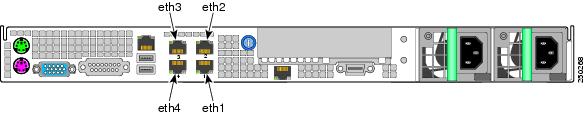
For software configuration, the RJ-45 NIC (Ethernet) ports on the Cisco CDE110 back panel are specified as eth1, eth2, eth3, and eth4 as shown in Figure 4-1.
Figure 4-1 NIC Port Numbering for Software Configuration
Note
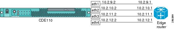
For the configuration examples in this section, Figure D-2 shows the IP addresses for interfaces eth1, eth2, eth3, and eth4 and the corresponding interfaces on the edge router.
Figure D-2 IP Addresses for VQE-S Configuration Examples
To configure the Linux operating system and other software for VQE-S, follow these steps:
Step 1
The operating system boots.
Step 2
Step 3
When creating the password, read and follow the directions that are provided for password security.
A valid password should be a mix of upper and lower case letters,digits, and other characters. You can use an 8 character longpassword with characters from at least 3 of these 4 classes, ora 7 character long password containing characters from all theclasses. An upper case letter that begins the password and adigit that ends it do not count towards the number of characterclasses used.A passphrase should be of at least 3 words, 12 to 40 characterslong and contain enough different characters.Step 4
•
•
•
As an example, for the eth1 interface, the /etc/sysconfig/network-scripts/ifcfg-eth1 file would include the following after the modifications:
ONBOOT=yesIPADDR=11.2.9.2NETMASK=255.255.255.0Step 5
[root@system]# ifup eth1Step 6
•
[root@system]# ifconfig eth1eth1 Link encap:Ethernet HWaddr 00:0E:0C:C6:F3:0Finet addr:11.2.10.2 Bcast:11.2.10.255 Mask:255.255.255.0inet6 addr: fe80::20e:cff:fec6:f30f/64 Scope:LinkUP BROADCAST RUNNING MULTICAST MTU:1500 Metric:1RX packets:3 errors:0 dropped:0 overruns:0 frame:0TX packets:36 errors:0 dropped:0 overruns:0 carrier:0collisions:0 txqueuelen:1000RX bytes:192 (192.0 b) TX bytes:2700 (2.6 KiB)Base address:0x3000 Memory:b8800000-b8820000•
[root@system]# ip link show eth1eth1: <BROADCAST,MULTICAST,UP,LOWER_UP> mtu 1500 qdisc pfifo_fast qlen 1000link/ether 00:0e:0c:c6:e4:fe brd ff:ff:ff:ff:ff:ff•
[root@system]# ping 11.2.9.1Step 7
11.2.9.2 starfire-iptvStep 8
HOSTNAME=starfire-iptv
Note
Step 9
[root@system]# passwd vqeEnter a password that follows the password guidelines.
The vqe username and password can be used log in to the VQE-S Application Monitoring Tool. This username and password cannot be used to log in to Linux directly using SSH.
Step 10
Configuring Static Routes for VQE-S
This section provides information on configuring static routes on the CDE110 that hosts VQE-S and on the directly attached router:
•
•
•
For the configuration examples in this section, Figure D-3 shows the IP addresses for interfaces eth1, eth2, eth3, and eth4 and the corresponding interfaces on the edge router.
Figure D-3 IP Addresses for VQE-S Configuration Examples
Configuring Default ECMP Routes for CDE110 Ethernet Interfaces (VQE-S Host)
On the Cisco CDE110 that hosts VQE-S, multiple Ethernet interfaces are used for incoming multicast streams, outgoing Unicast Retransmissions, and other traffic. In addition, some VQE deployments may use one of the Ethernet ports as the interface to a management network.
If a default route is configured for each Ethernet interface that is available to VQE-S for Unicast Retransmission and other traffic, Equal Cost Multipath (ECMP) is used to load balance output traffic across all of the listed nexthop interfaces.
To configure a default route for multiple CDE110 Ethernet interfaces, follow these steps:
Step 1
Step 2
default nexthop via next-hop-router1 [nexthop via next-hop-router2] ...In the preceding, the nexthop via next-hop-router construct repeats for as many next-hop router interfaces as are reachable through all of the configured CDE110 Ethernet interfaces. For example, if all four Ethernet interfaces are used by VQE-S for Unicast Retransmission, the line is as follows:
default nexthop via 11.2.9.1 nexthop via 11.2.10.1 nexthop via 11.2.11.1 nexthop via
11.2.12.1
In the preceding example, 11.2.9.1, 11.2.10.1, 11.2.11.1 , and 11.2.12.1 are the next-hop addresses on the router.
With this configuration in place, when the CDE110 system is rebooted, ECMP is used to load-balance output traffic across all of the listed next-hop interfaces.
Step 3
[root@system]# ip route showThe output will be similar to the following:
defaultnexthop via 11.2.9.1 dev eth1 weight 1nexthop via 11.2.10.1 dev eth2 weight 1nexthop via 11.2.11.1 dev eth3 weight 1nexthop via 11.2.12.1 dev eth4 weight 1
Configuring a Static Route for a CDE110 Management Interface (VQE-S Host)
If your deployment makes use of a management network, a static route for the management network can be configured using the /etc/sysconfig/network-scripts/route-interface-name file. The interface-name is eth1, eth2, eth3, or eth4. For example, the filename for the eth1 interface is route-eth1.
To configure a static route for a management network, follow these steps:
Step 1
Step 2
management-ip-addr/prefix-length nexthop via gateway-addrIn the preceding, the management-ip-addr/prefix-length is the IP address and prefix length for the management network. The gateway-addr is the IP address of the router interface that is directly attached to the CDE110 Ethernet port that will be used for management network traffic.
For this example, assume the following:
•
•
The following line configures a static route for eth1 and the management network:
10.0.0.0/8 nexthop via 11.2.9.1In the preceding example, 11.2.9.1 is the gateway-addr—the router interface that is directly attached to eth1. Figure D-3 shows the IP addresses used in this example for the eth1 interface and the directly attached router.
With this configuration in place, when the CDE110 system is rebooted, the management network static route is bound to the eth1 interface. The eth1 interface is used for management network traffic.
Note
Step 3
[root@system]# ip route showThe output will be similar to the following:
10.0.0.0/8 via 11.2.9.1 dev eth1defaultnexthop via 11.2.10.1 dev eth2 weight 1nexthop via 11.2.11.1 dev eth3 weight 1nexthop via 11.2.12.1 dev eth4 weight 1Configuring Static Routes for Feedback Targets on the Attached Router
When channels are configured with a channel-provisioning tool such as VQE Channel Provisioning Tool, it is required that you specify a unique Feedback Target (FBT) address for each channel. The router that is directly attached to the VQE-S host must have a static route configured for the FBT address so that the router can reach the target. If the FBT addresses are allocated within a contiguous address range, this configuration piece can be done with a single aggregated route.
For example, if the FBT addresses for the channels are assigned to be 8.86.1.1, 8.86.1.2, 8.86.1.3, ..., 8.86.1.250, then the single static route 8.86.1.0/24 configured on the directly attached router allows any of these FBT addresses to be reached. The commands on the router for the FBT addresses would be as follows:
configure terminalip route 8.86.1.0 255.255.255.0 11.2.9.2ip route 8.86.1.0 255.255.255.0 11.2.10.2ip route 8.86.1.0 255.255.255.0 11.2.11.2ip route 8.86.1.0 255.255.255.0 11.2.12.2As shown in Figure D-3, the IP addresses 11.2.9.2, 11.2.10.2, 11.2.11.2, and 11.2.12.2 have been assigned to the Ethernet interfaces on the VQE-S host. These interfaces are used for Unicast Retransmission.
Multicast Load Balancer and the Management Network
The /etc/opt/vqes/vqes.conf file has an option that allows you to specify the Ethernet interfaces that will be available to Multicast Load Balancer (MLB) for incoming multicast streams and outgoing Unicast Retransmissions. In the interface option for the MLB process, add the names of the Ethernet interfaces to reflect those interfaces that will be available for use by Multicast Load Balancer. By default, the interface option lists all four Ethernet interfaces as available to MLB.
•
•
Note
Enabling the VQE STUN Server (Optional)
If your deployment will use the VQE STUN Server so that set-top boxes behind NAT devices are supported by VQE, you must enable the STUN Server in the vqes.conf file. Unless you are sure that no set-top boxes being serviced by VQE-S are behind NAT devices, we recommend that you enable the STUN Server.
For detailed information on editing the vqes.conf file, see Appendix A, "Configuring VQE-S."
To enable the STUN Server, do the following:
Step 1
Step 2
Step 3
stun_server ={name = "STUN Server";exec = "/opt/vqes/bin/stun_server";privileged = true;## Enable/Disable setting for the STUN Server (optional)# Default value is true in case of absence# true- Start STUN Server# false- Do not start STUN Server#run = true;};Do not change any other values in the process definition section for the STUN Server.
Step 4
Configuring XML-RPC Port Numbers
The port numbers that VQE-S uses for XML-RPC are configured in two files:
•
•
Note
If your VQE-S deployment requires changes to the default XML-RPC port numbers for VQE-S, you need to make sure that the changes are coordinated so that the same port numbers for Process Monitor, Control Plane, and Multicast Load Balancer are specified in both the VQE-S configuration file and the VQE-S AMT configuration file. If you need to change a port number, use a text editor to modify each configuration file and save the file.
The default XML-RPC port numbers in the VQE-S AMT configuration file (/usr/share/tomcat5/webapps/ems/WEB-INF/vqe.conf) are as follows:
#VQE EMS: Configuration file for VQE management servers
#
# Copyright (c) 2007 by Cisco Systems, Inc.
# All rights reserved.
#
controlplane:8051
dataplane:8051
processmonitor:8050
mcastloadbalance:8052
Note
If you change the xmlrpc-port option for the Control Plane in vqes.conf, you must change the control plane and data plane values in the VQE-S AMT configuration file (shown above).The default port numbers used for VQE-S are the same as those shown above. For information on the VQE-S configuration file (/etc/opt/vqes/vqes.conf), see Appendix A, "Configuring VQE-S".
Configuring Net-SNMP (Optional)
The Cisco CDE110 that hosts VQE-S uses Net-SNMP, a third-party product, for SNMP support for some basic, non-VQE system services. Net-SNMP offers a set of built-in MIBs for Linux platforms. For more information on Net-SNMP support, see Appendix B, "Using Net-SNMP."
You must configure Net-SNMP on the Cisco CDE110 that hosts VQE-S. For information on configuring Net-SNMP, see the Net-SNMP web site:
http://www.net-snmp.com/
Ensuring That Only Trusted HTTPS Clients Can Push an SDP File
If your IPTV deployment will use VQE Channel Provisioning Tool (VCPT) to send channel information to the VQE Servers, it is recommended that you configure each CDE110 that hosts VQE-S so that only trusted HTTPS clients can send the channel information to the CDE110. For more information on VCPT and how it sends channel information, see "VQE Channel Provisioning Tool and Channel Information" section on page 1-11.
The iptables command provides a Linux-based, packet-filtering firewall that can be used to restrict HTTPS traffic to only trusted clients.
To allow only traffic from trusted HTTPS clients on the CDE110 port used for HTTPS, follow these steps:
Step 1
Step 2
iptables -A INPUT -p tcp --dport 444 -s VCPT_Host_IP_Address -j ACCEPT
In the preceding command, the following arguments specify the source and destination of the TCP traffic:
•
•
For example:
[root@system]# iptables -A INPUT -p tcp --dport 444 -s 10.86.17.200/32 -j ACCEPTStep 3
[root@system]# iptables -A INPUT -p tcp --dport 444 -j REJECTStep 4
[root@system]# iptables-save > /etc/sysconfig/iptablesSaving the current configuration to the iptables file ensures that the configuration will persist across reboots.
Starting VQE-S System Services and Verifying Status
To start system VQE-S system services and verify their status, follow these steps:
Step 1
[root@system]# /usr/bin/vqes_init_setup
Note
Table D-1 lists the system services that are started by the vqes_init_setup script.
Step 2
[root@system]# chkconfig --list | grep sshdsshd 0:off 1:off 2:on 3:on 4:on 5:on 6:off[root@system]# ps -ef | grep sshdroot 2835 1 0 Jul18 ? 00:00:00 /usr/sbin/sshdStep 3
[root@system]# chkconfig --list | grep httpdhttpd 0:off 1:off 2:on 3:on 4:on 5:on 6:off[root@system]# ps -ef | grep httpdroot 2880 1 0 Jul18 ? 00:00:00 /usr/sbin/httpdapache 4881 2880 0 04:03 ? 00:00:00 /usr/sbin/httpdapache 4882 2880 0 04:03 ? 00:00:00 /usr/sbin/httpdapache 4883 2880 0 04:03 ? 00:00:00 /usr/sbin/httpdapache 4884 2880 0 04:03 ? 00:00:00 /usr/sbin/httpdapache 4885 2880 0 04:03 ? 00:00:00 /usr/sbin/httpdapache 4886 2880 0 04:03 ? 00:00:00 /usr/sbin/httpdapache 4887 2880 0 04:03 ? 00:00:00 /usr/sbin/httpdapache 4888 2880 0 04:03 ? 00:00:00 /usr/sbin/httpdStep 4
[root@system]# chkconfig --list | grep tomcat5tomcat5 0:off 1:off 2:on 3:on 4:on 5:on 6:off[root@system]# ps -ef | grep tomcat5root 2915 1 0 Jul18 ? 00:00:11 /usr/java/default/bin/java -Djava.util.logging.manager=org.apache.juli.ClassLoaderLogManager -Djava.util.logging.config.file=/usr/share/tomcat5/conf/logging.properties -Djava.endorsed.dirs=/usr/share/tomcat5/common/endorsed -classpath :/usr/share/tomcat5/bin/bootstrap.jar:/usr/share/tomcat5/bin/commons-logging-api.jar -Dcatalina.base=/usr/share/tomcat5 -Dcatalina.home=/usr/share/tomcat5 -Djava.io.tmpdir=/usr/share/tomcat5/temp org.apache.catalina.startup.Bootstrap startStep 5
[root@system]# chkconfig --list | grep snmpdsnmpd 0:off 1:off 2:on 3:on 4:on 5:on 6:off[root@system]# ps -ef | grep snmpdroot 2812 1 0 Jul18 ? 00:00:58 /usr/sbin/snmpd -Lsd -Lf /dev/null -p /var/run/snmpd -aStep 6
[root@system]# chkconfig --list | grep snmpsasnmpsa 0:off 1:off 2:on 3:on 4:on 5:on 6:off[root@system]# ps -ef | grep snmpsaroot 2959 1 0 Jul18 ? 00:02:26 /usr/local/snmpsa/bin/smSubagent
Starting the VQE-S Processes and Verifying Status
To start the VQE-S processes and verify status, follow these steps:
Step 1
#vqes:3:respawn:/opt/vqes/bin/process_monitor -c /etc/opt/vqes/vqes.confThe line after the # character is removed is:
vqes:3:respawn:/opt/vqes/bin/process_monitor -c /etc/opt/vqes/vqes.confStep 2
[root@system]# init Q
Note
Step 3
[root@system]# ps -ef | grep vqeroot 2406 1 0 13:10 ? 00:00:00 /opt/vqes/bin/process_monitor -c /etc/opt/vqes/vqes.confvqes 2409 2406 0 13:10 ? 00:00:00 mlb --interface eth1 --xmlrpc-port 8052 --unicast-reservation 40 --poll-interval 1root 2411 2406 2 13:10 ? 00:00:00 vqes_dp --setcpu 0 --group vqesvqes 2415 2406 0 13:10 ? 00:00:00 vqes_cp --xmlrpc-port 8051 --cfg /etc/opt/vqes/vqe_channels.cfgroot 2422 3127 0 13:10 pts/0 00:00:00 grep vqeIn the preceding output, the VQE-S processes to check for are as follows:
•
•
•
•
Step 4
[root@system]# ps -elf | grep stun4 S root 18926 18919 0 75 0 - 3780 322792 Nov09 ? 00:03:29 stun_server --xmlrpc-port 80540 S root 31148 3359 0 78 0 - 971 pipe_w 12:46 ttyS1 00:00:00 grep stunStep 5
https://ip_address_of_VQES_hostLog in using the vqe username and password. (Any valid Linux username and password can be used to log in to the VQE-S Application Monitoring Tool.)
If you click System in the left pane, the VQE-S Application Monitoring Tool displays information on the VQE-S processes. Figure 4-2 shows an example.
Restarting the System and Verifying System and VQE-S Status
To restart the Cisco CDE110 and verify system and VQE-S status, follow these steps:
Note
Step 1
[root@system]# init 6The operating system boots.
Note
Step 2
Step 3
[root@system]# ifconfig -a... Output omittedStep 4
[root@system]# ps -ef | grep vqe... Output omittedStep 5
[root@system]# ps -elf | grep stun... Output omittedStep 6
[root@system]# ps -ef | grep sshd... Output omittedStep 7
[root@system]# ps -ef | grep httpd... Output omittedStep 8
[root@system]# ps -ef | grep tomcat5... Output omittedStep 9
[root@system]# ps -ef | grep snmpd... Output omittedStep 10
[root@system]# ps -ef | grep snmpsa... Output omittedStep 11
•
•
Setting Up a Cisco CDE110 That Hosts VCPT and VQE Client Channel Configuration Delivery Server
This section explains how to perform the initial configuration tasks for a Cisco CDE110 hosting VQE Channel Provisioning Tool (VCPT) and VQE Client Channel Configuration Delivery Server. Perform these tasks in the order shown:
1.
2.
3.
4.
5.
6.
Note
For information on upgrading an already configured Cisco CDE110 from Cisco VQE Release 2.0 to Release 2.1, see the Release Notes for Cisco CDA Visual Quality Experience, Release 2.1.
Prerequisites for a Cisco CDE110 That Hosts VCPT
This section explains tasks that should be performed before setting up a Cisco CDE110 that hosts VCPT.
Connecting Cables
The following cable connections are used on the Cisco CDE110 that hosts VCPT:
Note
•
•
•
Note
•
For the location of connectors on the Cisco CDE110 front and back panels, see the Cisco Content Delivery Engine 110 Hardware Installation Guide.
Setting Up SSL Certificates for VCPT
It is recommended that you deploy your own or commercial Secure Sockets Layer (SSL) certificates prior to beginning the tasks for setting up a Cisco CDE110 that hosts VCPT. For information on setting up the certificates, see the "Setting Up SSL Certificates" section on page 2-4.
Configuring the Linux Operating System for VCPT and VQE Client Channel Configuration Delivery Server
This section explains the initial Linux configuration tasks needed for a Cisco CDE110 appliance that will run VCPT and VQE Client Channel Configuration Delivery Server software. The explanation assumes that the needed software for Linux, VCPT, and VQE Client Channel Configuration Delivery Server have been pre-installed on the Cisco CDE110 appliance. For Red Hat Linux 5.0 documentation, go to the following web site:
http://www.redhat.com/docs/manuals/enterprise/
For software configuration, the RJ-45 NIC (Ethernet) ports on the Cisco CDE110 back panel are specified as eth1, eth2, eth3, and eth4 as shown in Figure 4-4.
Figure 4-4 NIC Port Numbering for Software Configuration
Note
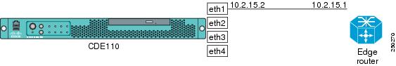
For the configuration examples in this section, Figure D-5 shows the IP addresses for interface eth1 and the corresponding interface on the edge router.
Figure D-5 IP Addresses for VCPT and VQE Client Channel Configuration Delivery Server Configuration Examples
Note
To configure the Linux operating system and other software for VCPT and VQE Client Channel Configuration Delivery Server, follow these steps:
Step 1
The operating system boots.
Step 2
Step 3
When creating the password, read and follow the directions that are provided for password security.
A valid password should be a mix of upper and lower case letters,digits, and other characters. You can use an 8 character longpassword with characters from at least 3 of these 4 classes, ora 7 character long password containing characters from all theclasses. An upper case letter that begins the password and adigit that ends it do not count towards the number of characterclasses used.A passphrase should be of at least 3 words, 12 to 40 characterslong and contain enough different characters.Step 4
•
•
•
As an example, for the eth1 interface, the /etc/sysconfig/network-scripts/ifcfg-eth1 file would include the following after the modifications:
ONBOOT=yesIPADDR=11.2.15.2NETMASK=255.255.255.0Step 5
[root@system]# ifup eth1Step 6
•
[root@system]# ifconfig eth1eth1 Link encap:Ethernet HWaddr 00:0E:0C:C6:F3:0Finet addr:11.2.15.2 Bcast:11.2.15.255 Mask:255.255.255.0inet6 addr: fe80::20e:cff:fec6:f30f/64 Scope:LinkUP BROADCAST RUNNING MULTICAST MTU:1500 Metric:1RX packets:3 errors:0 dropped:0 overruns:0 frame:0TX packets:36 errors:0 dropped:0 overruns:0 carrier:0collisions:0 txqueuelen:1000RX bytes:192 (192.0 b) TX bytes:2700 (2.6 KiB)Base address:0x3000 Memory:b8800000-b8820000•
[root@system]# ip link show eth1eth1: <BROADCAST,MULTICAST,UP,LOWER_UP> mtu 1500 qdisc pfifo_fast qlen 1000link/ether 00:0e:0c:c6:e4:fe brd ff:ff:ff:ff:ff:ff•
[root@system]# ping 11.2.15.1Step 7
11.2.15.2 starfire1-iptvStep 8
HOSTNAME=starfire1-iptv
Note
Step 9
[root@system]# passwd vqeEnter a password that follows the password guidelines.
The vqe username and password can be used to log in to the VQE Channel Provisioning Tool. This username and password cannot be used to log in to Linux directly using Secure Shell (SSH).
Step 10
Configuring a Static Route for a CDE110 Management Interface (VCPT Host)
Note
If your deployment makes use of a management network, a static route for the management network can be configured using the /etc/sysconfig/network-scripts/route-interface-name file. The interface-name is eth1, eth2, eth3, or eth4. For example, the filename for the eth1 interface is route-eth1.
To configure a static route for a management network, follow these steps:
Step 1
Step 2
management-ip-addr/prefix-length nexthop via gateway-addrIn the preceding, the management-ip-addr/prefix-length is the IP address and prefix length for the management network. The gateway-addr is the IP address of the router interface that is directly attached to the CDE110 Ethernet port that will be used for management network traffic.
For this example, assume the following:
•
•
The following line configures a static route for eth1 and the management network:
10.0.0.0/8 nexthop via 11.2.15.1In the preceding example, 11.2.15.1 is the gateway-addr—the router interface that is directly attached to eth1. Figure D-5 shows the IP addresses used in this example for the eth1 interface and the directly attached router.
With this configuration in place, when the CDE110 system is rebooted, the management network static route is bound to the eth1 interface. The eth1 interface is used for management network traffic.
Step 3
[root@system]# ip route showThe output will be similar to the following:
10.0.0.0/8 via 11.2.15.1 dev eth1Configuring Net-SNMP (Optional)
The CDE110 that hosts VCPT uses Net-SNMP, a third-party product, for SNMP support for some basic, non-VQE system services. Net-SNMP offers a set of built-in MIBs for Linux platforms. For more information on Net-SNMP support, see Appendix B, "Using Net-SNMP."
You must configure Net-SNMP on the Cisco CDE110 that hosts VCPT. For information on configuring Net-SNMP, see the Net-SNMP web site:
http://www.net-snmp.com/
Starting VCPT System Services and Verifying Status
To start VCPT system services and verify their status, follow these steps:
Step 1
[root@system]# /usr/bin/vqes_init_setup
Note
Table D-2 lists the system services that are started by the vqes_init_setup script.
Step 2
[root@system]# chkconfig --list | grep sshdsshd 0:off 1:off 2:on 3:on 4:on 5:on 6:off[root@system]# ps -ef | grep sshdroot 2835 1 0 Jul18 ? 00:00:00 /usr/sbin/sshdStep 3
[root@system]# chkconfig --list | grep httpdhttpd 0:off 1:off 2:on 3:on 4:on 5:on 6:off[root@system]# ps -ef | grep httpdroot 2880 1 0 Jul18 ? 00:00:00 /usr/sbin/httpdapache 4881 2880 0 04:03 ? 00:00:00 /usr/sbin/httpdapache 4882 2880 0 04:03 ? 00:00:00 /usr/sbin/httpdapache 4883 2880 0 04:03 ? 00:00:00 /usr/sbin/httpdapache 4884 2880 0 04:03 ? 00:00:00 /usr/sbin/httpdapache 4885 2880 0 04:03 ? 00:00:00 /usr/sbin/httpdapache 4886 2880 0 04:03 ? 00:00:00 /usr/sbin/httpdapache 4887 2880 0 04:03 ? 00:00:00 /usr/sbin/httpdapache 4888 2880 0 04:03 ? 00:00:00 /usr/sbin/httpdStep 4
[root@system]# chkconfig --list | grep tomcat5tomcat5 0:off 1:off 2:on 3:on 4:on 5:on 6:off[root@system]# ps -ef | grep tomcat5root 2915 1 0 Jul18 ? 00:00:11 /usr/java/default/bin/java -Djava.util.logging.manager=org.apache.juli.ClassLoaderLogManager -Djava.util.logging.config.file=/usr/share/tomcat5/conf/logging.properties -Djava.endorsed.dirs=/usr/share/tomcat5/common/endorsed -classpath :/usr/share/tomcat5/bin/bootstrap.jar:/usr/share/tomcat5/bin/commons-logging-api.jar -Dcatalina.base=/usr/share/tomcat5 -Dcatalina.home=/usr/share/tomcat5 -Djava.io.tmpdir=/usr/share/tomcat5/temp org.apache.catalina.startup.Bootstrap startStep 5
[root@system]# chkconfig --list | grep snmpdsnmpd 0:off 1:off 2:on 3:on 4:on 5:on 6:off[root@system]# ps -ef | grep snmpdroot 2812 1 0 Jul18 ? 00:00:58 /usr/sbin/snmpd -Lsd -Lf /dev/null -p /var/run/snmpd -aStep 6
[root@system]# chkconfig --list | grep snmpsasnmpsa 0:off 1:off 2:on 3:on 4:on 5:on 6:off[root@system]# ps -ef | grep snmpsaroot 2959 1 0 Jul18 ? 00:02:26 /usr/local/snmpsa/bin/smSubagent
Starting the VQE Client Channel Configuration Delivery Server Process and Verifying Status
This section explains how to start the VQE Client Channel Configuration Delivery Server (VCDS) process and verify that the process is running and that VCPT is available.
Note
To start the VQE Client Channel Configuration Delivery Server process and verify that it is running, follow these steps:
Step 1
[root@system]# init QStep 2
[root@system]# ps -ef | grep VCDSroot 2928 1 0 01:31 ? 00:00:00 /opt/vqes/bin/VQECCfgDeliveryServer -f /etc/opt/vqes/VCDServer.cfgStep 3
https://ip_address_of_VCPT_hostLog in using the vqe username and password. (Any valid Linux username and password can be used to log in to VCPT.)
If you are able to log in successfully, VCPT is running correctly.
Restarting the System and Verifying System, VCPT, and VQE Client Channel Configuration Delivery Server Status
To restart the Cisco CDE110 and verify system, VCPT, and VQE Client Channel Configuration Delivery Server status, follow these steps:
Note
Step 1
[root@system]# init 6The operating system boots.
Step 2
Step 3
[root@system]# ifconfig -a... Output omittedStep 4
[root@system]# ps -ef | grep sshd... Output omittedStep 5
[root@system]# ps -ef | grep httpd... Output omittedStep 6
[root@system]# ps -ef | grep tomcat5... Output omittedStep 7
[root@system]# ps -ef | grep snmpd... Output omittedStep 8
[root@system]# ps -ef | grep snmpsa... Output omittedStep 9
[root@system]# ps -ef | grep -i VCDS... Output omittedStep 10
https://ip_address_of_VCPT_hostLog in with a Linux username and password.
If you are able to log in successfully, VCPT is running correctly.
Step 11
•
•