Table Of Contents
About Cisco Validated Design (CVD) Program
Cisco Solution for EMC VSPEX Microsoft Hyper-V Architectures
Cisco Unified Computing System
Cisco UCS C220 M3 Rack-Mount Servers
EMC Storage Technologies and Benefits
Solution architecture overview
Architecture for 50 Microsoft Hyper-V virtual machines
Defining the Reference Workload
Applying the Reference Workload
Networking Configuration Guidelines
VSPEX Configuration Guidelines
VSPEX M50 Configuration Details
Prepare and Configure the Cisco Nexus 3048 Switch
Initial Setup of Nexus Switches
Global Port-Channel Configuration
Global Spanning-Tree Configuration
Ethernet Interface Port Descriptions
Virtual Port-Channel (vPC) Global Configuration
Storage Connections Configuration
Server Connections Configurations
Prepare the Cisco UCS C220 M3 Servers
Configure Cisco Integrated Management Controller (CIMC)
Enabling Virtualization Technology in BIOS
Install Microsoft Windows Server 2012 on Cisco UCS C220 M3 Servers
Connect and log into the Cisco UCS C-Series Standalone Server CIMC Interface
Host Rename and Active Directory Domain Join
Configure the Hyper-V Virtual Switch
Modify Windows Server 2012 iSCSI Registry Parameters
Prepare the EMC VNXe3150 Storage
Configure Advanced Features - Jumbo Frames
Configure iSCSI Storage Servers
Create Hosts and Provide Host Access
Microsoft Windows Failover Cluster Setup
Configure MPIO on Windows Server 2012
Validating Cisco Solution for EMC VSPEX MS Hyper-V Architectures
Verify the Redundancy of the Solution Components
Customer Configuration Data Sheet
Cisco Virtualization Solution for EMC VSPEX with Microsoft Windows Server 2012 Hyper-V for 50 Virtual MachinesLast Updated: May 30, 2013
Building Architectures to Solve Business Problems
About the Authors
Sanjeev Naldurgkar, Technical Marketing Engineer, Server Access Virtualization Business Unit, Cisco SystemsSanjeev Naldurgkar is a Technical Marketing Engineer at Cisco Systems with Server Access Virtualization Business Unit (SAVBU). With over 12 years of experience in information technology, his focus areas include UCS, Microsoft product technologies, server virtualization, and storage technologies. Prior to joining Cisco, Sanjeev was Support Engineer at Microsoft Global Technical Support Center. Sanjeev holds a Bachelor's Degree in Electronics and Communication Engineering and Industry certifications from Microsoft, and VMware.
Acknowledgements
For their support and contribution to the design, validation, and creation of the Cisco Validated Design, I would like to thank:
•
Tim Cerling-Cisco
•
•
•
•
•
•
•
About Cisco Validated Design (CVD) Program
The CVD program consists of systems and solutions designed, tested, and documented to facilitate faster, more reliable, and more predictable customer deployments. For more information visit:
http://www.cisco.com/go/designzone
ALL DESIGNS, SPECIFICATIONS, STATEMENTS, INFORMATION, AND RECOMMENDATIONS (COLLECTIVELY, "DESIGNS") IN THIS MANUAL ARE PRESENTED "AS IS," WITH ALL FAULTS. CISCO AND ITS SUPPLIERS DISCLAIM ALL WARRANTIES, INCLUDING, WITHOUT LIMITATION, THE WARRANTY OF MERCHANTABILITY, FITNESS FOR A PARTICULAR PURPOSE AND NONINFRINGEMENT OR ARISING FROM A COURSE OF DEALING, USAGE, OR TRADE PRACTICE. IN NO EVENT SHALL CISCO OR ITS SUPPLIERS BE LIABLE FOR ANY INDIRECT, SPECIAL, CONSEQUENTIAL, OR INCIDENTAL DAMAGES, INCLUDING, WITHOUT LIMITATION, LOST PROFITS OR LOSS OR DAMAGE TO DATA ARISING OUT OF THE USE OR INABILITY TO USE THE DESIGNS, EVEN IF CISCO OR ITS SUPPLIERS HAVE BEEN ADVISED OF THE POSSIBILITY OF SUCH DAMAGES.
THE DESIGNS ARE SUBJECT TO CHANGE WITHOUT NOTICE. USERS ARE SOLELY RESPONSIBLE FOR THEIR APPLICATION OF THE DESIGNS. THE DESIGNS DO NOT CONSTITUTE THE TECHNICAL OR OTHER PROFESSIONAL ADVICE OF CISCO, ITS SUPPLIERS OR PARTNERS. USERS SHOULD CONSULT THEIR OWN TECHNICAL ADVISORS BEFORE IMPLEMENTING THE DESIGNS. RESULTS MAY VARY DEPENDING ON FACTORS NOT TESTED BY CISCO.
The Cisco implementation of TCP header compression is an adaptation of a program developed by the University of California, Berkeley (UCB) as part of UCB's public domain version of the UNIX operating system. All rights reserved. Copyright © 1981, Regents of the University of California.
Cisco and the Cisco Logo are trademarks of Cisco Systems, Inc. and/or its affiliates in the U.S. and other countries. A listing of Cisco's trademarks can be found at http://www.cisco.com/go/trademarks. Third party trademarks mentioned are the property of their respective owners. The use of the word partner does not imply a partnership relationship between Cisco and any other company. (1005R)
Any Internet Protocol (IP) addresses and phone numbers used in this document are not intended to be actual addresses and phone numbers. Any examples, command display output, network topology diagrams, and other figures included in the document are shown for illustrative purposes only. Any use of actual IP addresses or phone numbers in illustrative content is unintentional and coincidental.
© 2013 Cisco Systems, Inc. All rights reserved.
Cisco Virtualization Solution for EMC VSPEX with Microsoft Windows Server 2012 Hyper-V for 50 Virtual Machines
Executive Summary
Cisco solution for EMC VSPEX proven and modular infrastructures are built with best of-breed technologies to create complete virtualization solutions that enable you to make an informed decision in the hypervisor, compute, and networking layers. VSPEX eases server virtualization planning and configuration burdens. VSPEX accelerate your IT Transformation by enabling faster deployments, greater flexibility of choice, efficiency, and lower risk. This Cisco Validated Design document focuses on the Microsoft Hyper-V architecture for 50 virtual machines with Cisco solution for EMC VSPEX.
Introduction
As part of an effort to improve and enhance the performance and capabilities of its product line, Cisco and EMC from time to time release revisions of its hardware and software. Therefore, some functions described in this guide may not be supported by all revisions of the software or hardware currently in use. For the most up-to-date information on product features, refer to your product release notes.
Target Audience
The reader of this document is expected to have the necessary training and background to install and configure Microsoft Hyper-V, EMC VNXe, and Cisco Nexus 3048 switches, and Cisco Unified Computing System (UCS) C220 M3 rack servers. External references are provided where applicable and it is recommended that the reader be familiar with these documents.
Readers are also expected to be familiar with the infrastructure and database security policies of the customer installation.
Purpose of this Document
This document describes the steps required to deploy and configure a Cisco solution for EMC VSPEX for Microsoft Hyper-V architectures to a level that will allow for confirmation that the basic components and connections are working correctly. The document covers one Microsoft Hyper-V architecture i.e. Hyper-V for 50 Virtual Machines. While readers of this document are expected to have sufficient knowledge to install and configure the products used, configuration details that are important to this solution's performance are specifically mentioned.
Business Needs
VSPEX solutions are built with proven best-of-breed technologies to create complete virtualization solutions that enable you to make an informed decision in the hypervisor, server, and networking layers coupled with EMC unified Storage and Next Generation Backup. VSPEX infrastructures accelerate your IT transformation by enabling faster deployments, greater flexibility of choice, efficiency, and lower risk.
Business applications are moving into the consolidated compute, network, and storage environment. Cisco solution for EMC VSPEX for Microsoft Hyper-V helps to reduce every component of a traditional deployment. The complexity of integration management is reduced while maintaining the application design and implementation options. Administration is unified, while process separation can be adequately controlled and monitored. The following are the business needs for the Cisco solution of EMC VSPEX Microsoft Hyper-V architectures:
•
•
•
Solutions Overview
Cisco Solution for EMC VSPEX Microsoft Hyper-V Architectures
This solution provides an end-to-end architecture with Cisco, EMC, and Microsoft technologies that demonstrate support for up to 50 generic virtual machines and provides high availability and server redundancy.
The following are the components used for the design and deployment:
•
•
•
•
•
•
The solution is designed to host scalable, mixed application workloads. The scope of this CVD is limited to the Cisco solution for EMC VSPEX Microsoft Hyper-V solutions for 50 virtual machines only. For additional scale and different virtualization solution, please refer to other VSPEX architectures.
Technology Overview
Cisco Unified Computing System
The Cisco Unified Computing System is a next-generation data center platform that unites computing, network, storage access, and virtualization into a single cohesive system.
The main components of the Cisco UCS are:
•
•
•
•
The Cisco Unified Computing System is designed to deliver:
•
•
•
•
Cisco UCS C220 M3 Rack-Mount Servers
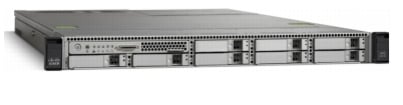
Building on the success of the Cisco UCS C200 M2 Rack Servers, the enterprise-class Cisco UCS C220 M3 server further extends the capabilities of the Cisco Unified Computing System portfolio in a 1-rack-unit (1RU) form factor. And with the addition of the Intel® Xeon® processor E5-2600 product family, it delivers significant performance and efficiency gains.
Figure 1 Cisco UCS C220 M3 Rack Server
The Cisco UCS C220 M3 offers up to 256 GB of RAM, up to eight drives or SSDs, and two 1GE LAN interfaces built into the motherboard, delivering outstanding levels of density and performance in a compact package.
Cisco Nexus 3048 Switch
The Cisco Nexus® 3048 Switch is a line-rate Gigabit Ethernet top-of-rack (ToR) switch and is part of the Cisco Nexus 3000 Series Switches portfolio. The Cisco Nexus 3048, with its compact one-rack-unit (1RU) form factor and integrated Layer 2 and 3 switching, complements the existing Cisco Nexus family of switches. This switch runs the industry-leading Cisco® NX-OS Software operating system, providing customers with robust features and functions that are deployed in thousands of data centers worldwide.
Figure 2 Cisco Nexus 3048 Switch
EMC Storage Technologies and Benefits
The EMC VNXe™ family is optimized for virtual applications delivering industry-leading innovation and enterprise capabilities for file, block, and object storage in a scalable, easy-to-use solution. This next-generation storage platform combines powerful and flexible hardware with advanced efficiency, management, and protection software to meet the demanding needs of today's enterprises.
The VNXe™ series is powered by Intel Xeon processor, for intelligent storage that automatically and efficiently scales in performance, while ensuring data integrity and security.
The VNXe series is purpose-built for the IT manager in smaller environments and the VNX series is designed to meet the high-performance, high-scalability requirements of midsize and large enterprises. The EMC VNXe and VNX storage arrays are multi-protocol platform that can support the iSCSI, NFS, and CIFS protocols depending on the customer's specific needs. The solution was validated using iSCSI for data storage.
VNXe series storage arrays have following customer benefits:
•
•
•
•
•
Software Suites Available
•
•
•
Software Packs Available
Total Value Pack — Includes all protection software suites and the Security and Compliance Suite
This is the available EMC protection software pack.
The VNXe™ series is powered by Intel Xeon processor, for intelligent storage that automatically and efficiently scales in performance, while ensuring data integrity and security.
The VNXe series is purpose-built for the IT manager in smaller environments. The EMC VNXe storage arrays are multi-protocol platforms that can support the iSCSI, NFS, and CIFS protocols depending on the customer's specific needs. The solution was validated using iSCSI for data storage.
EMC Avamar
EMC's Avamar® data deduplication technology seamlessly integrates into virtual environments, providing rapid backup and restoration capabilities. Avamar's deduplication results in vastly less data traversing the network, and greatly reduces the amount of data being backed up and stored - translating into storage, bandwidth and operational savings.
The following are two of the most common recovery requests made to backup administrators:
File-level recovery—Object-level recoveries account for the vast majority of user support requests. Common actions requiring file-level recovery are-individual users deleting files, applications requiring recoveries, and batch process-related erasures.
System recovery—Although complete system recovery requests are less frequent in number than those for file-level recovery, this bare metal restore capability is vital to the enterprise. Some common root causes for full system recovery requests are-viral infestation, registry corruption, or unidentifiable unrecoverable issues.
The Avamar System State protection functionality adds backup and recovery capabilities in both of these scenarios.
Microsoft Windows Server 2012
Hyper-V is an integral part of Windows Server and provides a foundational virtualization platform that enables you to transition to the cloud. With Windows Server 2012 you get a compelling solution for core virtualization scenarios - production server consolidation, dynamic datacenter, business continuity, VDI, and test & development.
Hyper-V provides you better flexibility with features like live migration and cluster shared volumes for storage flexibility.
Hyper-V also delivers greater scalability with support for up to 320 logical processors on hardware, 4 TB of physical memory, 64 virtual processors, and up to 1 TB of memory on a virtual machine. Up to 64 nodes and 8,000 virtual machines in a cluster also can be supported. With Non-Uniform Memory Access (NUMA) support inside virtual machines, guest operating systems and applications can make intelligent NUMA decisions and improvements to the dynamic memory feature of Hyper-V in Windows Server 2012; you can attain higher consolidation numbers with improved reliability for restart operations.
Architectural overview
This CVD focuses on Microsoft Hyper-V solution for up to 50 virtual machines.
For the VSPEX solution, the reference workload was defined as a single virtual machine. Characteristics of a virtual machine are defined in Table 1.
See "Sizing Guideline" section for more detailed information.
Solution architecture overview
Table 2 lists the mix of hardware components, their quantities and software components used for Microsoft Hyper-V solution for 50 Virtual Machines.
Table 3 lists the various hardware and software versions of the components which occupies different tiers of the Cisco solution for EMC VSPEX Microsoft architectures under test.
Table 4 outlines the C220 M3 server configuration across all the Microsoft Hyper-V architectures. The table shows the configuration on per server basis.
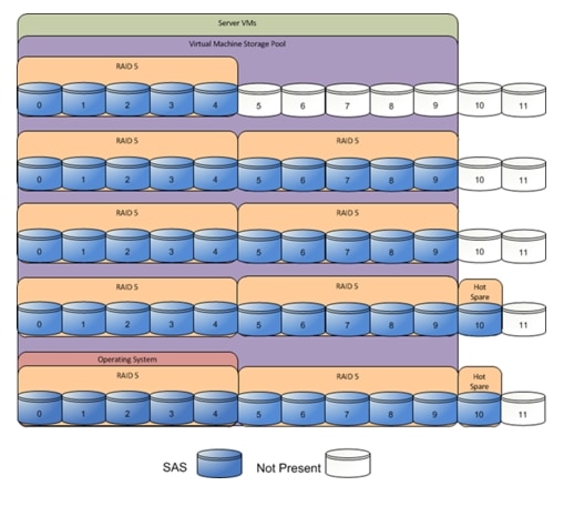
Storage Guidelines
The architecture diagram in this section shows the physical disk layout. Disk provisioning on the VNXe series is simplified through the use of wizards, so that administrators do not choose which disks belong to a given storage pool. The wizard may choose any available disk of the proper type, regardless of where the disk physically resides in the array
The reference architecture uses the following configuration:
Following are the disk allocations for VSPEX M50 architectures:
•
•
The VNX/VNXe family is designed for five 9s availability by using redundant components throughout the array. All of the array components are capable of continued operation in case of hardware failure. The RAID disk configuration on the array provides protection against data loss due to individual disk failures, and the available hot spare drives can be dynamically allocated to replace a failing disk.
Figure 3 Target Storage layout for EMC VSPEX M50 Solution
Table 5 provides size of datastores for M50 architecture laid out in Figure 3.
Table 5 Datastore Details for M50 Architecture
Disk capacity and type
300GB SAS
Number of disks
45
RAID type
4 + 1 RAID 5 groups
Number of RAID groups
9
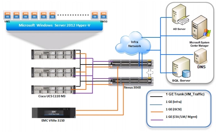
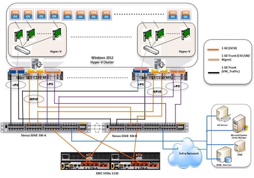
The VSPEX M50 reference architecture assumes there is an existing infrastructure / management network available where a virtual machine or physical machine hosting SCVMM server, Database server and Windows Active Directory and DNS servers are present. Figure 4 demonstrate high level solution architecture for up to 50 virtual machines.
Figure 4 Referrence Architecture for 50 Virtual Machines
As it is evident in the above diagrams, following are the high level design points of Microsoft Hyper-V architectures:
•
•
•
This design does not dictate or require any specific layout of infrastructure network which hosts the SCVMM, Database, and Active Directory servers. However, design does require accessibility of certain VLANs from the infrastructure network to reach the servers.
Microsoft Windows Server 2012 Hyper-V is used as hypervisor operating system on each server and is installed on local hard drives. Typical maximum load is 25 virtual machines per server.
Architecture for 50 Microsoft Hyper-V virtual machines
Figure 5 demonstrates logical layout of 50 Microsoft Hyper-V virtual machines. Following are the key aspects of this solution:
•
•
•
•
•
Figure 5 Logical Layout Diagram for 50 Virtual Machines
Sizing Guideline
In any discussion about virtual infrastructures, it is important to first define a reference workload. Not all servers perform the same tasks, and it is impractical to build a reference that takes into account every possible combination of workload characteristics.
Defining the Reference Workload
To simplify the discussion, we have defined a representative reference workload. By comparing your actual usage to this reference workload, you can extrapolate which reference architecture to choose.
For the VSPEX solutions, the reference workload was defined as a single virtual machine. This virtual machine characteristics is shown in Table 1. This specification for a virtual machine is not intended to represent any specific application. Rather, it represents a single common point of reference to measure other virtual machines.
Applying the Reference Workload
When considering an existing server that will move into a virtual infrastructure, you have the opportunity to gain efficiency by right-sizing the virtual hardware resources assigned to that system.
The reference architectures create a pool of resources sufficient to host a target number of reference virtual machines as described above. It is entirely possible that your virtual machines may not exactly match the specifications above. In that case, you can say that a single specific virtual machine is the equivalent of some number of reference virtual machines, and assume that that number of virtual machines have been used in the pool. You can continue to provision virtual machines from the pool of resources until it is exhausted. Consider these examples:
Example 1 Custom Built Application
A small custom-built application server needs to move into this virtual infrastructure. The physical hardware supporting the application is not being fully utilized at present. A careful analysis of the existing application reveals that the application can use one processor and needs 3 GB of memory to run normally. The IO workload ranges between 4 IOPS at idle time to 15 IOPS when busy. The entire application is only using about 30 GB on local hard drive storage.
Based on these numbers, the following resources are needed from the resource pool:
•
•
•
•
In this example, a single virtual machine uses the resources of two of the reference VMs. If the original pool had the capability to provide 50 VMs worth of resources, the new capability is 48 VMs.
Example 2 Point of Sale System
The database server for a customer's point-of-sale system needs to move into this virtual infrastructure. It is currently running on a physical system with four CPUs and 16 GB of memory. It uses 200 GB storage and generates 200 IOPS during an average busy cycle.
The following are the requirements to virtualize this application:
•
•
•
•
In this case the one virtual machine uses the resources of eight reference virtual machines. If this was implemented on a resource pool for 50 virtual machines, there are 42 virtual machines of capability remaining in the pool.
Example 3 Web Server
The customer's web server needs to move into this virtual infrastructure. It is currently running on a physical system with two CPUs and 8GB of memory. It uses 25 GB of storage and generates 50 IOPS during an average busy cycle.
The following are the requirements to virtualize this application:
•
•
•
•
In this case the virtual machine would use the resources of four reference virtual machines. If this was implemented on a resource pool for 50 virtual machines, there are 46 virtual machines of capability remaining in the pool.
Summary of Example
The three examples presented illustrate the flexibility of the resource pool model. In all three cases the workloads simply reduce the number of available resources in the pool. If all three examples were implemented on the same virtual infrastructure, with an initial capacity of 50 virtual machines they can all be implemented, leaving the capacity of thirty six reference virtual machines in the resource pool.
In more advanced cases, there may be tradeoffs between memory and I/O or other relationships where increasing the amount of one resource decreases the need for another. In these cases, the interactions between resource allocations become highly complex, and are outside the scope of this document. However, once the change in resource balance has been examined, and the new level of requirements is known; these virtual machines can be added to the infrastructure using the method described in the examples. You can also use the Microsoft Assessment and Planning (MAP) Toolkit to assist in the analysis of the current workload. It can be downloaded from http://www.microsoft.com/map.
Networking Configuration Guidelines
This document provides details for setting up a redundant, highly-available configuration. As such, references are made as to which component is being configured with each step whether that be A or B. For example, SP A and SP B, are used to identify the two EMC VNXe storage controllers that are provisioned with this document while Switch A and Switch B identify the pair of Cisco Nexus switches that are configured. Additionally, this document details steps for provisioning multiple UCS hosts and these are identified sequentially, M50N1 and M50N2, and so on. Finally, when indicating that the reader should include information pertinent to their environment in a given step, this is indicated with the inclusion of <italicized/regular text> as part of the command. See the following example for the VLAN create command on Nexus:
switchA(config)# vlan {vlan-id | vlan-range}Example:
switchA(config)# vlan <storage VLAN ID>This document is intended to allow the reader to fully configure the customer environment. In order to do so, there are various steps which will require you to insert your own naming conventions, IP addresses, and VLAN schemes, as well as record appropriate iSCSI IQN name or MAC addresses. Table 7 details the list of VLANs necessary for deployment as outlined in this guide
VSPEX Configuration Guidelines
The configuration for Cisco solution for EMC VSPEX Microsoft Hyper-V architectures is divided into the following steps:
1.
2.
3.
4.
5.
6.
7.
8.
Next pages go into details of each section mentioned above.
Pre-deployment Tasks
Pre-deployment tasks include procedures that do not directly relate to environment installation and configuration, but whose results will be needed at the time of installation. Examples of pre-deployment tasks are collection of hostnames, IP addresses, VLAN IDs, license keys, installation media, and so on. These tasks should be performed before the customer visit to decrease the time required onsite.
•
•
•
Customer Configuration Data
To reduce the onsite time, information such as IP addresses and hostnames should be assembled as part of the planning process.
"Customer Configuration Data Sheet" section provides a set of tables to maintain a record of relevant information. This form can be expanded or contracted as required, and information may be added, modified, and recorded as deployment progresses.
Additionally, complete the VNXe Series Configuration Worksheet, available on the EMC online support website, to provide the most comprehensive array-specific information.
Infrastructure Servers
Most environments will already have DNS and Active Directory services in their infrastructure either running on a virtual machine or on a physical server. This section will not cover the installation and configuration of DNS and Active Directory Domain Controllers.
The following infrastructure servers were used to validate the VSPEX Microsoft Hyper-V architectures.
Table 6 Infrastructure Server Details
M50AD.M50VSPEX.COM
DC,DNS and DHCP
10.29.150.90-Mgmt
10.10.23.90-vm_traffic
Windows Server 2012
VSPEX M50 Configuration Details
Cabling Information
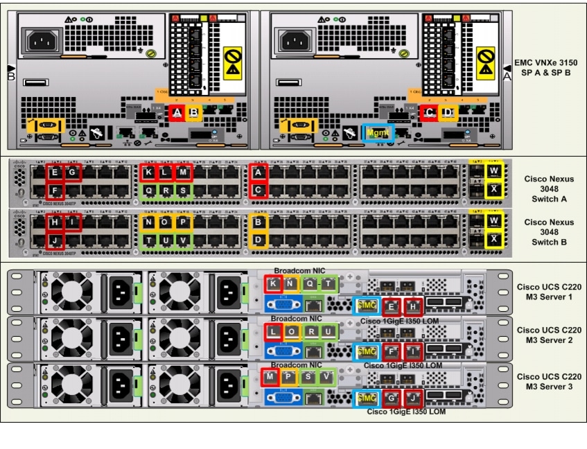
The following information is provided as a reference for cabling the physical equipment in a VSPEX M50 environment. Figure 7 and Figure 8 in this section provide both local and remote device and port locations in order to simplify cabling requirements.
This document assumes that out-of-band management ports are plugged into an existing management infrastructure at the deployment site.
Be sure to follow the cable directions in this section. Failure to do so will result in necessary changes to the deployment procedures that follow because specific port locations are mentioned. Before starting, be sure that the configuration matches what is described in Figure 6, Figure 7, and Figure 8.
Figure 6 shows a VSPEX M50 cabling diagram. The labels indicate connections to end points rather than port numbers on the physical device. For example, connection A is a 1 Gb target port connected from EMC VNXe3150 SP B to Cisco Nexus 3048 A and connection R is a 1 Gb target port connected from Broadcom NIC 3 on Server 2 to Cisco Nexus 3048 B. Connections W and X are 10 Gb vPC peer-links connected from Cisco Nexus 3048 A to Cisco Nexus 3048 B.
Figure 6 VSPEX M50 Cabling Diagram
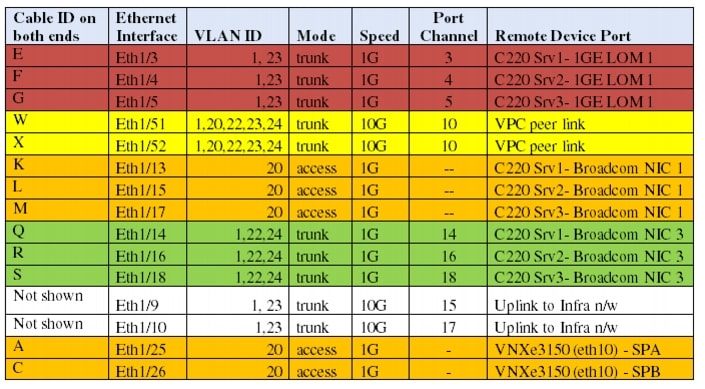
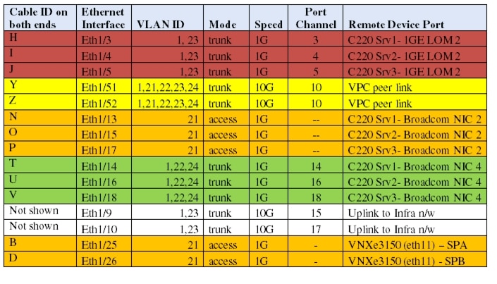
From Figure 7 and Figure 8 in this section, there are five major cabling sections in these architectures:
1.
2.
3.
4.
5.
Figure 7 Cisco Nexus 3048-A Ethernet Cabling Information
Figure 8 Cisco Nexus 3048-B Ethernet Cabling Information
Connect all the cables as outlined in the Figure 6, Figure 7, and Figure 8.
Prepare and Configure the Cisco Nexus 3048 Switch
The following section provides a detailed procedure for configuring the Cisco Nexus 3048 switches for use in EMC VSPEX M50 solution.
Figure 9 shows two switches configured for vPC. In vPC, a pair of switches acting as vPC peer endpoints looks like a single entity to port-channel-attached devices, although the two devices that act as logical port-channel endpoint are still two separate devices. This provides hardware redundancy with port-channel benefits. Both switches form a vPC Domain, in which one vPC switch is Primary while the other is secondary.
Note
Figure 9 Network Configuration for EMC VSPEX M50
Initial Setup of Nexus Switches
This section details the Cisco Nexus 3048 switch configuration for use in a VSPEX M50 environment.
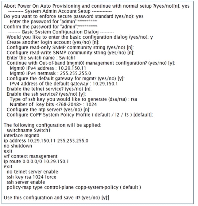
On initial boot and connection to the serial or console port of the switch, the NX-OS setup should automatically start. This initial configuration addresses basic settings such as the switch name, the mgmt0 interface configuration, and SSH setup and defines the control plane policing policy.
Initial Configuration of Cisco Nexus 3048 Switch A and B
Figure 10 Initial Configuration
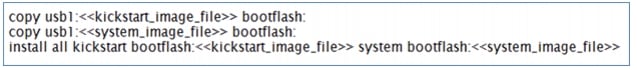
Software Upgrade (Optional)
It is always recommended to perform any required software upgrades on the switch at this point in the configuration. Download and install the latest available NX-OS software for the Cisco Nexus 3048 switch from the Cisco software download site. There are various methods to transfer both the NX-OS kickstart and system images to the switch. The simplest method is to leverage the USB port on the Switch. Download the NX-OS kickstart and system files to a USB drive and plug the USB drive into the external USB port on the Cisco Nexus 3048 switch.
Copy the files to the local bootflash and update the switch by using the following procedure.
Figure 11 Procedure to update the Switch
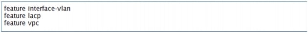
Enable Features
Enable certain advanced features within NX-OS. This is required for configuring some additional options. Enter configuration mode using the (config t) command, and type the following commands to enable the appropriate features on each switch.
Enabling Features in Cisco Nexus 3048 Switch A and B
Figure 12 Command to Enable Features
Global Port-Channel Configuration
The default port-channel load-balancing hash uses the source and destination IP to determine the load-balancing algorithm across the interfaces in the port channel. Better distribution across the members of the port channels can be achieved by providing more inputs to the hash algorithm beyond the source and destination IP. For this reason, adding the source and destination TCP port to the hash algorithm is highly recommended.
From configuration mode (config t), type the following commands to configure the global port-channel load-balancing configuration on each switch.
Configuring Global Port-Channel Load-Balancing on Cisco Nexus Switch A and B
Figure 13 Commands to Configure Global Port-Channel and Load-Balancing
Global Spanning-Tree Configuration
The Cisco Nexus platform leverages a new protection feature called bridge assurance. Bridge assurance helps to protect against a unidirectional link or other software failure and a device that continues to forward data traffic when it is no longer running the spanning-tree algorithm. Ports can be placed in one of a few states depending on the platform, including network and edge.
The recommended setting for bridge assurance is to consider all ports as network ports by default. From configuration mode (config t), type the following commands to configure the default spanning-tree options, including the default port type and BPDU guard on each switch.
Configuring Global Spanning-Tree on Cisco Nexus Switch A and B
Figure 14 Configuring Spanning-Tree
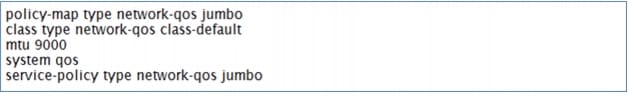
Enable Jumbo Frames
Cisco solution for EMC VSPEX Microsoft Hyper-V architectures require MTU set at 9000 (jumbo frames) for efficient storage and live migration traffic. MTU configuration on Nexus 5000 series switches fall under global QoS configuration. You may need to configure additional QoS parameters as needed by the applications.
From configuration mode (config t), type the following commands to enable jumbo frames on each switch.
Enabling Jumbo Frames on Cisco Nexus 3048 Switch A and B
Figure 15 Enabling Jumbo Frames
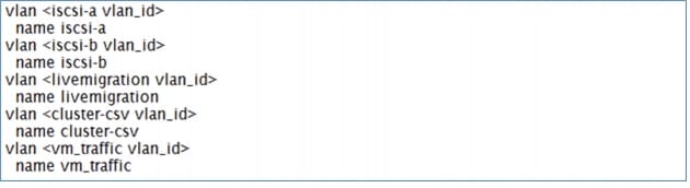
Configure VLANs
For VSPEX M50 configuration, create the layer 2 VLANs on both the Cisco Nexus 3048 Switches using the Table 7 as reference. Create your own VLAN definition table with the help of "Customer Configuration Data Sheet" section.
From configuration mode (config t), type the following commands to define and describe the L2 VLANs.
Defining L2 VLANs on Cisco Nexus 3048 Switch A and B
Figure 16 Commands to Define L2 VLANs
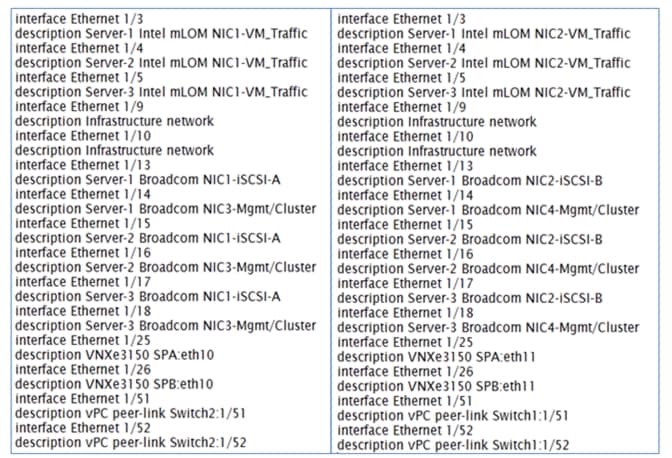
Ethernet Interface Port Descriptions
This section shows the steps to set descriptions on all the interfaces.
Figure 17 Descriptions on All the Interfaces
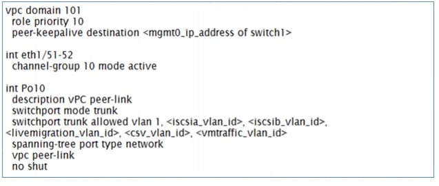
Virtual Port-Channel (vPC) Global Configuration
The vPC feature requires an initial setup between the two Cisco Nexus switches to function properly. From configuration mode (config t), type the following commands to configure the vPC global configuration for Switch A.
Configuring vPC Global on Cisco Nexus Switch A
Figure 18 Commands to Configure vPC Global Configuration on Switch A
From configuration mode (config t), type the following commands to configure the vPC global configuration for Switch B.
Configuring vPC Global on Cisco Nexus Switch B
Figure 19 Commands to Configure vPC Global Configuration on Switch B
Storage Connections Configuration
Switch interfaces connected to the VNXe storage ports are configured as access ports. Each controller will have two links to each switch.
From the configuration mode (config t), type the following commands on each switch to configure the individual interfaces.
Cisco Nexus 3048 Switch A with VNXe SPA configuration
Figure 20 Commands to Configure VNXe Interface on Switch A
Cisco Nexus 3048 Switch B with VNXe SPA configuration
Figure 21 Commands to Configure VNXe Interface on Switch B
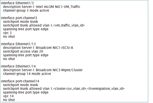
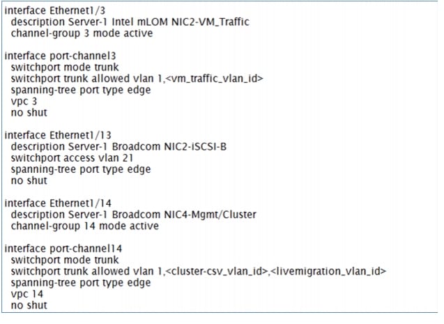
Server Connections Configurations
Each server has six network adapters (two Intel and four Broadcom ports) connected to both switches for redundancy as shown in Figure 9. This section provides the steps to configure the interfaces on both the switches that are connected to the servers.
Cisco Nexus Switch A with Server 1 configuration
Figure 22 Commands to Configure Interface on Switch A for Server 1 Connectivity
Cisco Nexus Switch B with Server 1 configuration
Figure 23 Commands to Configure Interface on Switch B and Server 1 Connectivity
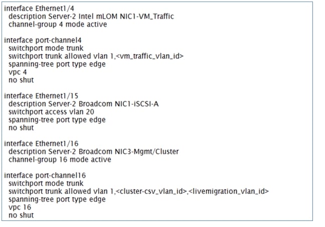
Cisco Nexus Switch A with Server 2 configuration
Figure 24 Commands to Configure Interface on Switch A and Server 2 Connectivity
Cisco Nexus Switch B with Server 2 configuration
Figure 25 Commands to Configure Interface on Switch B and Server 2 Connectivity
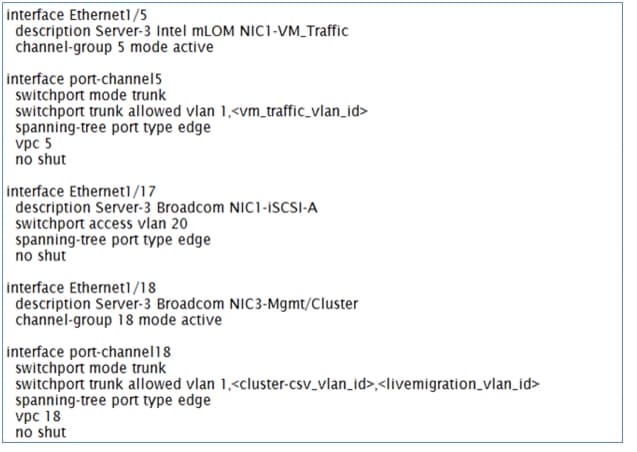
Cisco Nexus Switch A with Server 3 configuration
Figure 26 Commands to Configure Interface on Switch A and Server 3 Connectivity
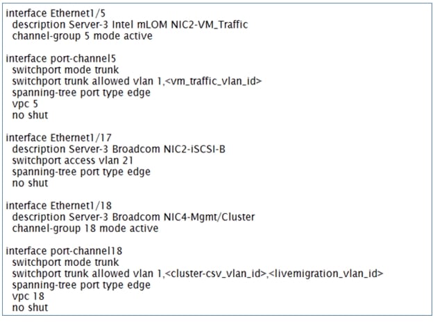
Cisco Nexus Switch B with Server 3 configuration
Figure 27 Commands to Configure Interface on Switch B and Server 3 Connectivity
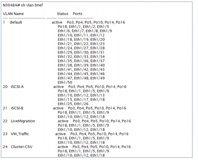
At this point, all the ports and port-channels are configured with necessary VLANs, switchport mode and vPC configuration. Validate this configuration using the show port-channel summary and show vlan brief commands as shown in Figure 28 and Figure 29.
Figure 28 Show vlan brief
Ensure that on both switches, all required VLANs are in active status and right set of ports and port-channels are part of the necessary VLANs.
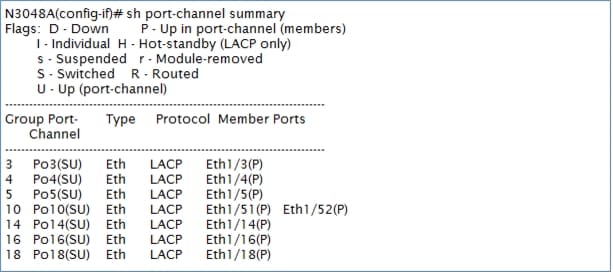
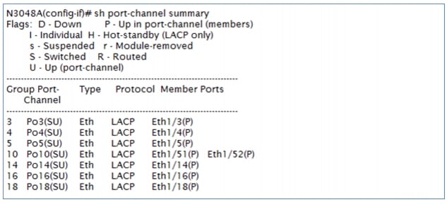
Port-channel configuration can be verified using show port-channel summary command. Figure 29 shows the expected output of this command after completing the NIC teaming of Ethernet interfaces on the host covered in "Network Configuration" section.
Figure 29 Show Port-Channel Summary Output
In this example, port-channel 10 is the vPC peer-link port-channel, port-channels 3, 4 and 5 are connected to the Cisco 1GigE I350 LOM on the host and port-channels 14, 16 and 18 are connected to the Broadcom NICs on the host. Make sure that state of the member ports of each port-channel is "P" (Up in port-channel). Note that port may not come up if the peer ports are not properly configured. Common reasons for port-channel port being down are:
•
•
vPC status can be verified using show vpc brief command. Example output is shown in Figure 30:
Figure 30 Show vpc Brief Output
Make sure that vPC peer status is peer adjacency formed ok and all the port-channels, including the peer-link port-channel, have status up.
Infrastructure Servers
Most environments will already have DNS and Active Directory services in their infrastructure either running on a virtual machine or on a physical server. This section will not cover the installation and configuration of DNS and Active Directory Domain Controllers.
Prepare the Cisco UCS C220 M3 Servers
This section provides the detailed procedure for configuring a Cisco Unified Computing System C-Series standalone server for use in VSPEX M50 configurations. Perform all the steps mentioned in this section on all the hosts.
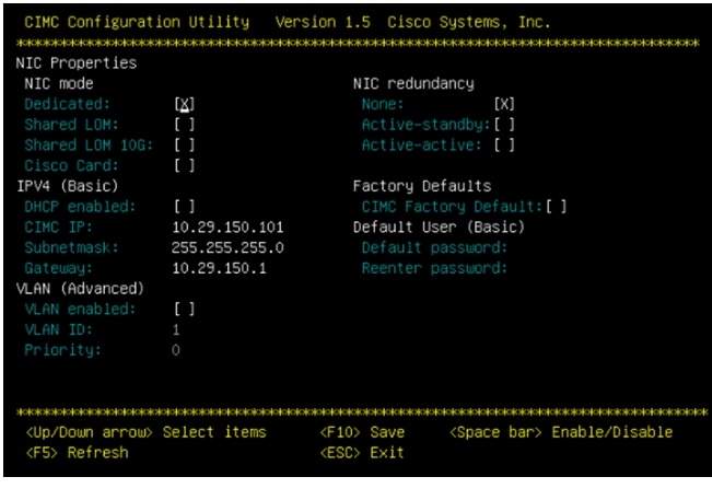
Configure Cisco Integrated Management Controller (CIMC)
These steps describe the setup of the initial Cisco UCS C-Series standalone server. Follow these steps on all servers:
1.
2.
3.
4.
5.
6.
7.
Figure 31 CIMC Configuration Utility
Once the CIMC IP is configured, the server can be managed using the https based Web GUI or CLI.
Note
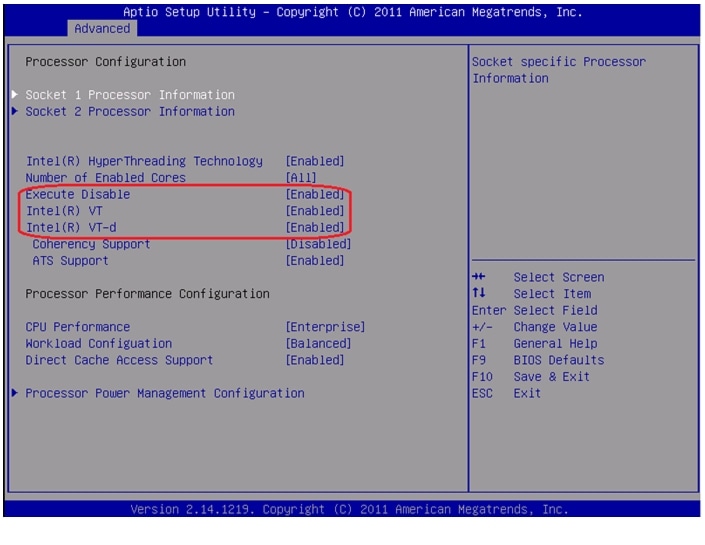
Enabling Virtualization Technology in BIOS
Hyper-V requires an x64-based processor, hardware-assisted virtualization (Intel VT enabled), and hardware data execution protection (Execute Disable enabled). Follow these steps on all the servers to enable Intel ® VT and Execute Disable in BIOS:
1.
2.
3.
Figure 32 Cisco UCS C220 M3 KVM Console
4.
Configuring RAID
The RAID controller type is Cisco UCSC RAID SAS 2008 and supports 0, 1, 5 RAID levels. We need to configure RAID level 1 for this setup and set the virtual drive as boot drive.
To configure RAID controller, follow these steps on all the servers:
1.
2.
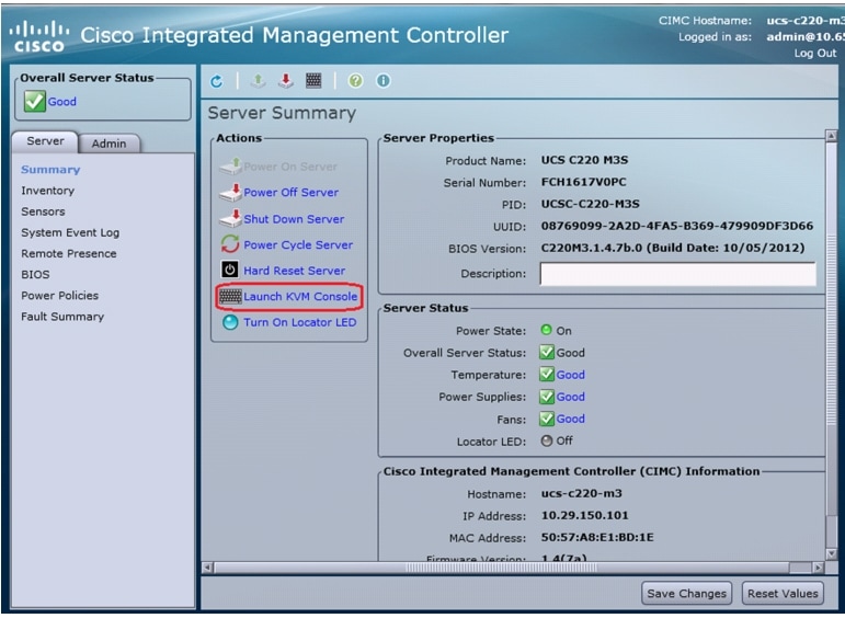
Figure 33 Cisco UCS C220 M3 CIMC GUI
3.
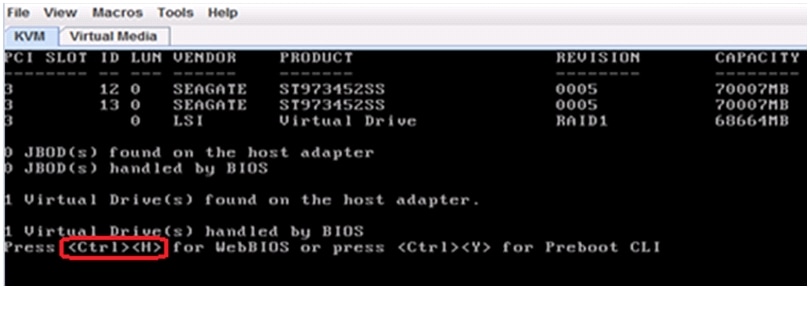
Figure 34 Cisco UCS C220 M3 KVM Console - Server Booting
4.
Figure 35 Adapter Selection for RAID Configuration
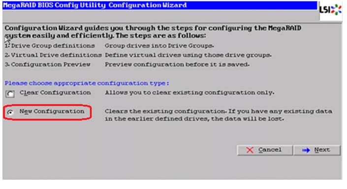
5.
Figure 36 MegaRAID BIOS Config Utility Configuration Wizard
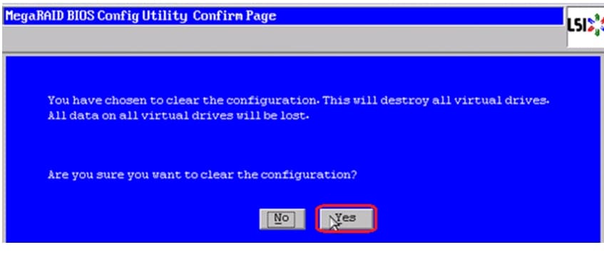
6.
Figure 37 MegaRAID BIOS Config Utility Confirmation Page
7.
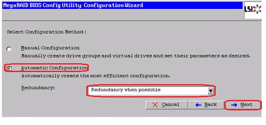
Figure 38 MegaRAID BIOS Config Utility Configuration Wizard - Select Configuration Method
8.
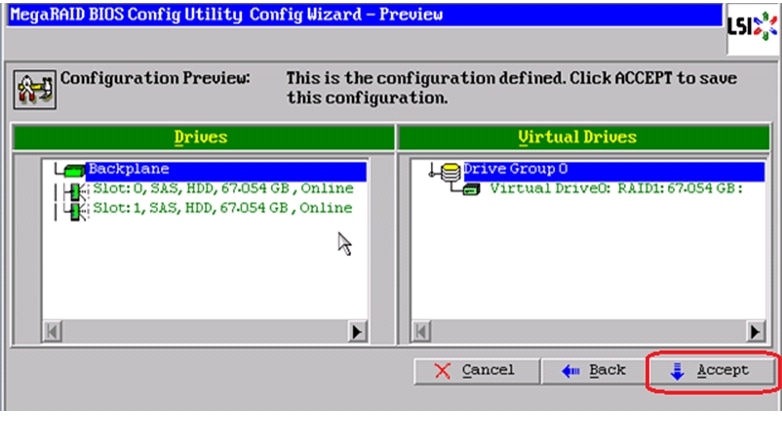
Figure 39 MegaRAID BIOS Config Utility Config Wizard - Preview
9.
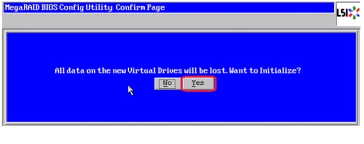
Figure 40 MegaRAID BIOS Config Utility Confirmation Page
10.
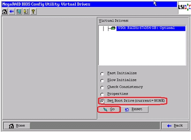
Figure 41 MegaRAID BIOS Config Utility Virtual Drives
11.
Figure 42 MegaRAID BIOS Config Utility Virtual Configuration
Install Microsoft Windows Server 2012 on Cisco UCS C220 M3 Servers
This section provides detailed procedures for installing Windows Server 2012 in an M50 VSPEX configuration. Multiple methods exist for installing Windows Server in such an environment. This procedure highlights using the virtual KVM console and virtual media features within the Cisco UCS C-Series CIMC interface to map remote installation media to each individual server.
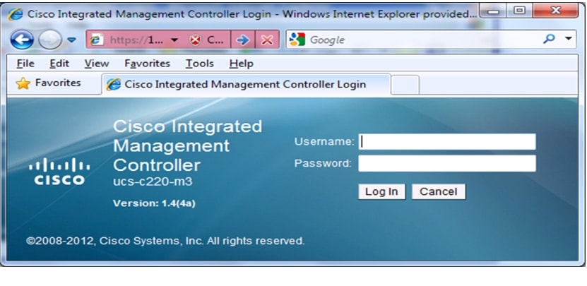
Connect and log into the Cisco UCS C-Series Standalone Server CIMC Interface
1.
2.
Figure 43 CIMC Manager Login Page
3.
4.
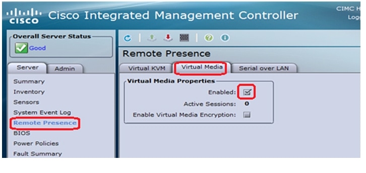
5.
a.
b.
c.
Figure 44 CIMC Manager Remote Presence - Virtual Media
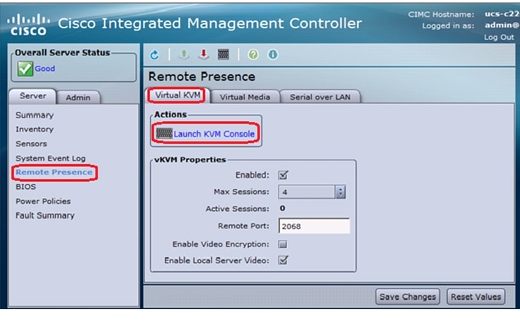
6.
Figure 45 CIMC Manager Remote Presence - Virtual KVM
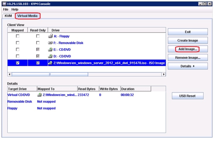
7.
8.
Figure 46 CIMC Manager Virtual Media - Add Image
9.
10.
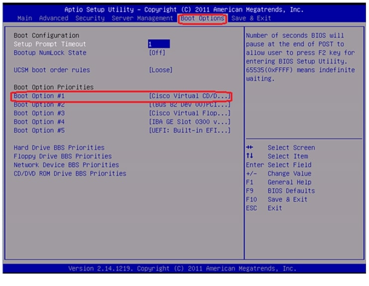
11.
Figure 47 Cisco UCS C220 M3 BIOS Setup Utility
12.
Install Windows Server 2012
1.
2.
3.
4.
5.
6.
7.
8.
9.
10.
11.
12.
13.
14.
http://software.cisco.com/download/type.html?mdfid=284296253&flowid=31742
Network Configuration
To configure the network for each Hyper-V host, follow these steps:
1.
2.
3.
Rename-NetAdapter -InterfaceAlias <Ethernet> -NewName <Mgmt-Member1>Rename-NetAdapter -InterfaceAlias <"Ethernet 3"> -NewName <Mgmt-Member2>Rename-NetAdapter -InterfaceAlias <"Ethernet 6"> -NewName <VM-Member1>Rename-NetAdapter -InterfaceAlias <"Ethernet 5"> -NewName <VM-Member2>Rename-NetAdapter -InterfaceAlias <"Ethernet 2"> -NewName <iSCSI-A>Rename-NetAdapter -InterfaceAlias <"Ethernet 4"> -NewName <iSCSI-B>
Note
4.
Set-NetAdapterAdvancedProperty -Name
<Mgmt-Member1,Mgmt-Member2,VM-Member1,VM-Member2> -DisplayName "Jumbo
Packet" -DisplayValue "9014 Bytes" -EA SilentlyContinue
Set-NetAdapterAdvancedProperty -Name <Mgmt-Member1,Mgmt-Member2,VM-Member1,VM-Member2> -DisplayName "Jumbo Packet" -DisplayValue "9014" -EA SilentlyContinue
Note
5.
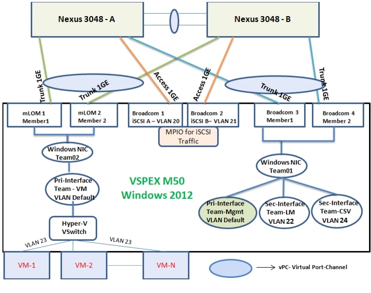
NIC teaming is done using the in-built Windows 2012 NIC Teaming feature (also known as Load Balancing/Failover - LBFO) for bandwidth aggregation and redundancy in case of a component failure.
Figure 48 Windows NIC Teaming Logical Representation
a.
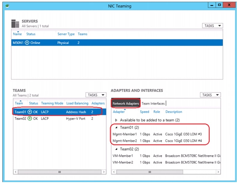
New-NetLbfoTeam -Name <Team01> -TeamMembers <Mgmt-Member1,Mgmt-Member2>
-TeamNicName <MgmtOS> -TeamingMode Lacp -a
Figure 49 NIC Teaming GUI - Team 01 Members
Add-NetLbfoTeamNic -Team <Team01> -VlanID <22> -Name <LM> -aAdd-NetLbfoTeamNic -Team <Team01> -VlanID <24> -Name <CSV> -ab.
Figure 50 Teaming GUI - Team 01 tNICs
c.
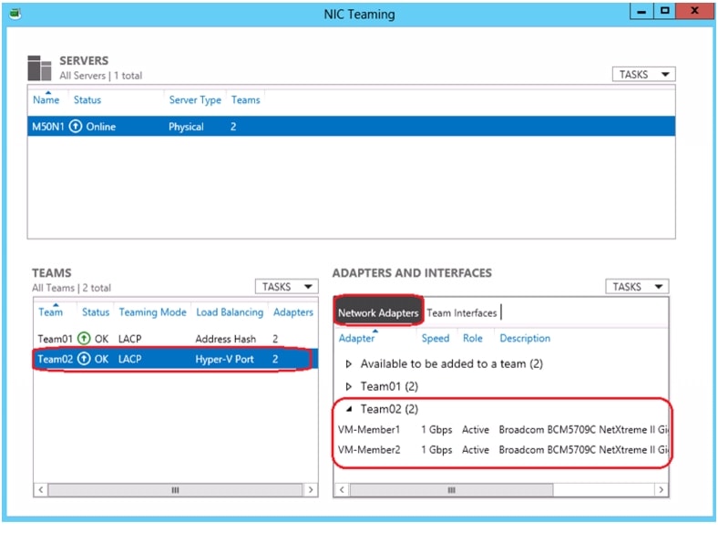
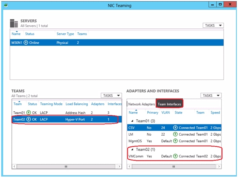
New-NetLbfoTeam -Name <Team02> -TeamMembers <VM-Member1,VM-Member2>
-TeamNicName <VMComm> -TeamingMode Lacp -LoadBalancingAlgorithm HyperVPort -a
Figure 51 NIC Teaming GUI - Team02 Members
Figure 52 NIC Teaming GUI - Team02 tNICs
Note
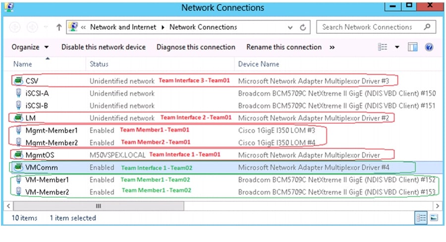
Figure 53 Network Connections
Windows Server 2012 NIC Teaming (LBFO) Deployment and Management Guide can be downloaded from the below URL:
http://www.microsoft.com/en-in/download/details.aspx?id=30160
6.
New-NetIPAddress -InterfaceAlias <MgmtOS> -IPAddress <10.29.150.92>
-DefaultGateway <10.29.150.1> -PrefixLength <24>
New-NetIPAddress -InterfaceAlias <LM> -IPAddress <10.10.22.21> -PrefixLength <24>New-NetIPAddress -InterfaceAlias <CSV> -IPAddress <10.10.24.21> -PrefixLength <24>New-NetIPAddress -InterfaceAlias <iSCSI-A> -IPAddress <10.10.20.21> -PrefixLength <24>New-NetIPAddress -InterfaceAlias <iSCSI-B> -IPAddress <10.10.21.21> -PrefixLength <24>7.
Set-DnsClient -InterfaceAlias <iSCSI-A,iSCSI-B,CSV,LM> -Register $false8.
Set-DnsClientServerAddress -InterfaceAlias <MgmtOS> -ServerAddresses
<10.29.150.90>
In the above command replace the <MgmtOS> with the name of the NIC used for management traffic and add an IP address of your DNS server next to -ServerAdddress.
Host Rename and Active Directory Domain Join
1.
Rename-Computer -NewName <m50n>1 -restartIn the above command replace the <m50n1> with a name per your organization's naming standard.
2.
Add-Computer -DomainName <m50vspex> -RestartIn the above command replace the <m50vspex> with the Active Directory domain name in your network.
Install Roles and Features
Install Hyper-V, Failover-Clustering, Multipath I/O roles/features and restart the host.
Add-WindowsFeature Hyper-V, Failover-Clustering, Multipath-IO
-IncludeManagementTools -Restart
Configure the Hyper-V Virtual Switch
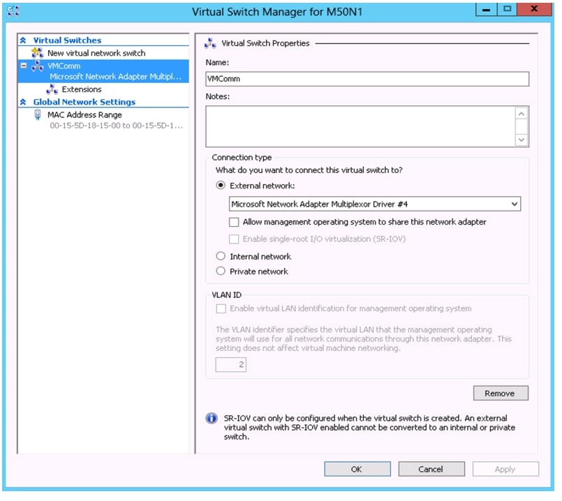
1.
New-VMSwitch -Name VMComm -NetAdapterName VMComm -AllowManagementOS $falseIn the above command replace the <VMComm> with the name of your team interface created for VM traffic.
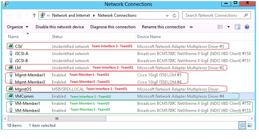
Figure 54 Hyper-V Virtual Switch Manager
Figure 55 Network Connections
2.
New-VMSwitch -Name iSCSI-A -NetAdapterName iSCSI-A -AllowManagementOS $true
-EnableIov $true
New-VMSwitch -Name iSCSI-B -NetAdapterName iSCSI-B -AllowManagementOS $true -EnableIov $trueIn the above command replace the <iSCSI-A> and <iSCSI-B> with the name of your network adapter used for iSCSI traffic.
Modify Windows Server 2012 iSCSI Registry Parameters
The registry settings in Table 9 should be modified on each server running iSCSI to the VNXe. The settings apply for both the native Windows Server 2012 MPIO DSM and PowerPath unless otherwise noted.
1.
2.
3.
4.
HKEY_LOCAL_MACHINE\SYSTEM\CurrentControlSet\Control\Class\{***}\***\Parameters
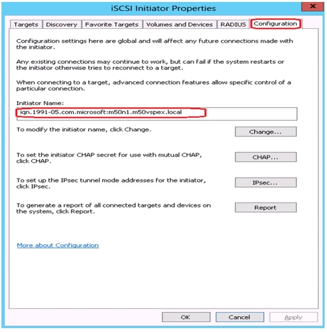
Enable Host iSCSI Initiator
1.
2.
Set-Service -Name MSiSCSI -StartupType Automatic3.
Start-Service -Name MSiSCSI4.
Figure 56 iSCSI Initiator Properties - Configuration
Prepare the EMC VNXe3150 Storage
This section explains:
•
•
•
•
Initial Setup of VNXe
1.
2.
http://www.emc.com/support-training/support/emc-powerlink.htm
3.
Figure 57 EMC Unisphere - Dashboard Page
Note
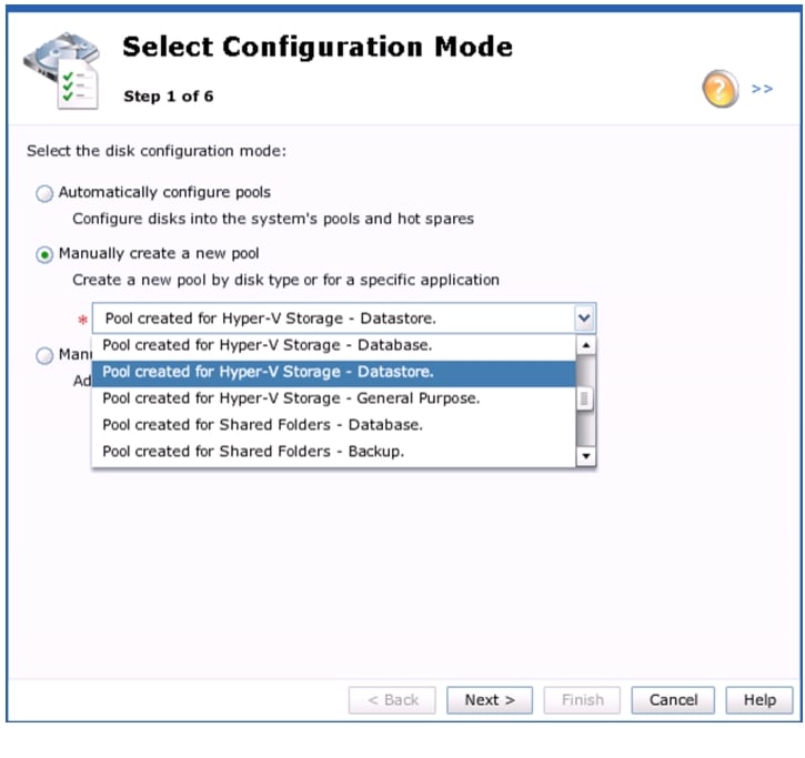
Create Storage Pools
Create a pool with the appropriate number of disks as suggested in Figure 3.
1.
2.
3.
Figure 58 EMC Unisphere - Select Mode in Disk Configuration Wizard
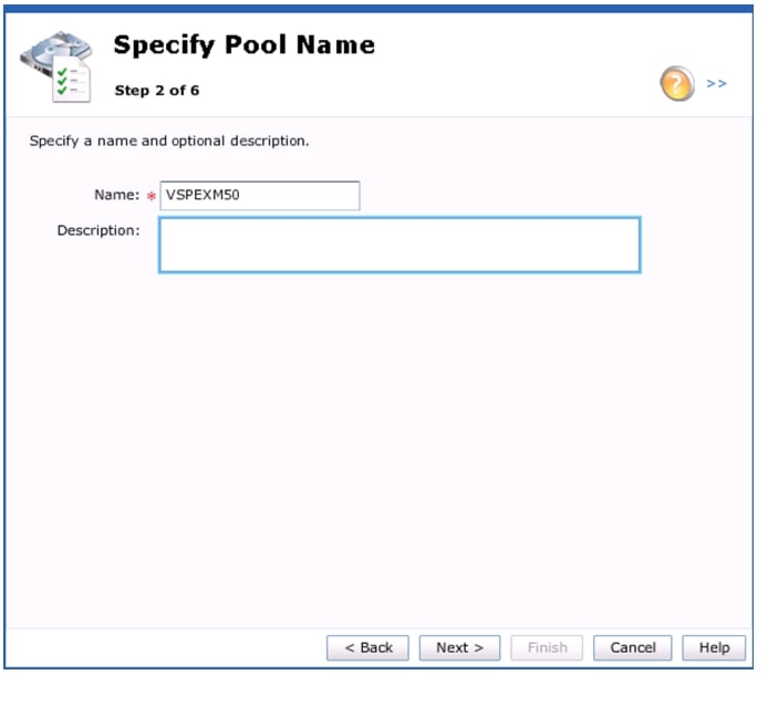
4.
5.
Figure 59 EMC Unisphere - Specify Pool Name in Disk Configuration Window
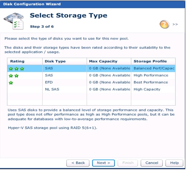
6.
Figure 60 EMC Unisphere - Select Storage Type in Disk Configuration Wizard
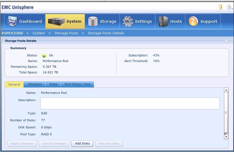
Figure 61 shows the details of the Storage Pool created.
Figure 61 EMC Unisphere - Storage Pool Details
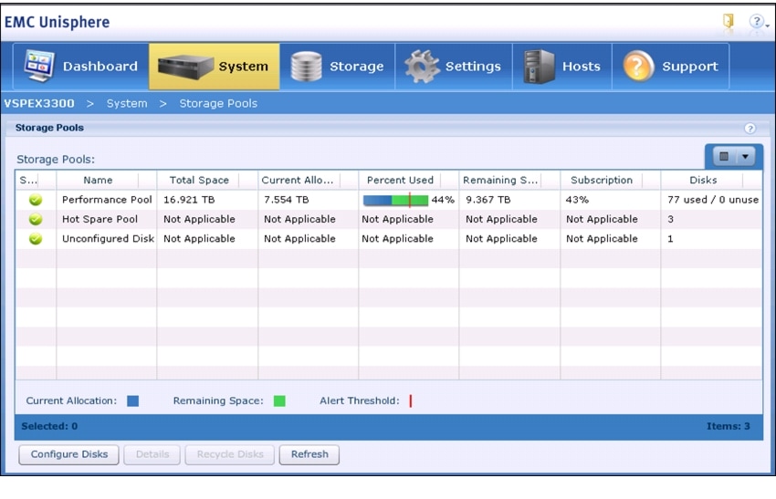
Figure 62 EMC Unisphere - Storage Pools
Note
•
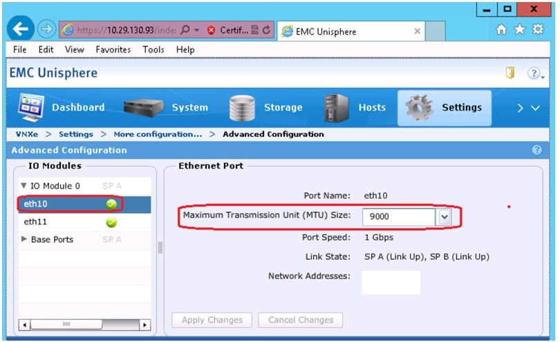
Configure Advanced Features - Jumbo Frames
The Cisco networking environment will have a Maximum Transmission Unit (MTU) size of 9000 for the iSCSI connections to the VNXe. In order to match the configured MTU size via Unisphere, follow these steps:
1.
2.
3.
Figure 63 EMC Unisphere - Advanced Configuration
iSCSI Server Configuration
The iSCSI Storage Server is the portal through which storage will be accessed by the hosts within the Fast Track configuration. The goal of the proposed iSCSI server configuration is to provide redundancy, multi-pathing and balanced access across all 1 GigE connections and both storage processors. Each 1 GigE module will have 2 ports, referred to as eth10 and eth11. Considering there is an I/O module for each service processor, both SPA and SPB will have eth10 and eth11 connections.
iSCSI servers will run on either SPA or SPB. This means storage assigned to a given iSCSI server will only be available to one SP at a given time. To utilize both SPA and SPB concurrently, two iSCSI servers will be created.
With respect to iSCSI server high availability, the eth10 and eth11 connections are paired across the service processors. If an iSCSI server running with an IP address dedicated to eth10 on SP A needs to move to SP B, for maintenance as an example, the IP address will move to the corresponding eth10 port on SPB. Therefore subnet connectivity will need to be the same for the associated eth10 and eth11 connections across the service processors. The Figure 64 shows a logical example of the connections.
Figure 64 VNXe Array Logical Network Connections
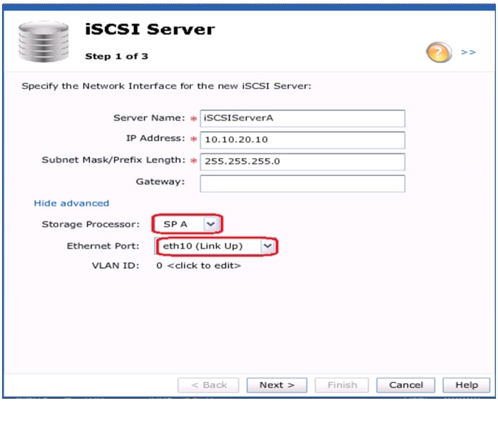
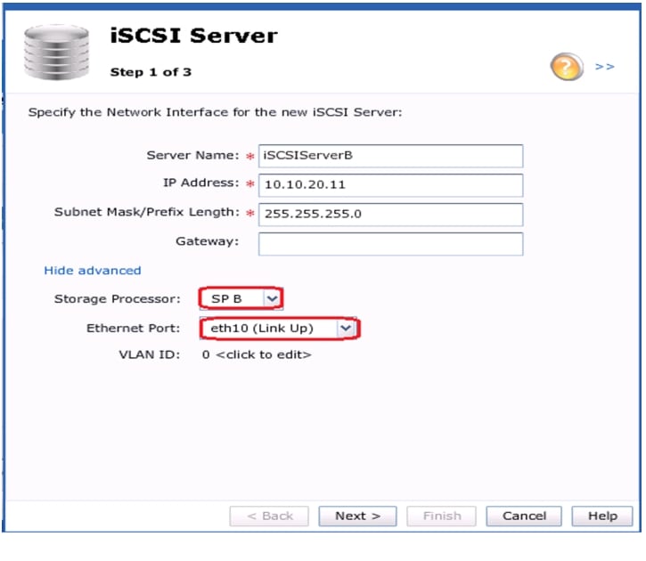
Configure iSCSI Storage Servers
1.
2.
Figure 65 EMC Unisphere - iSCSI Server SP-A eth10
3.
Figure 66 EMC Unisphere - iSCSI Server SP-B eth10
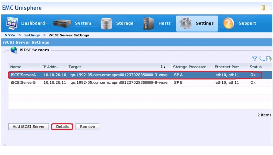
4.
Figure 67 EMC Unisphere - iSCSI Server Settings
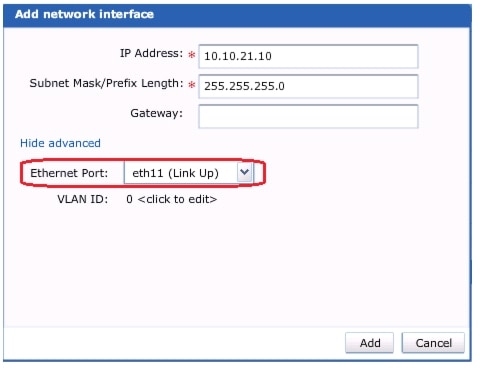
5.
6.
Figure 68 EMC Unisphere - iSCSI Server SP-A eth11
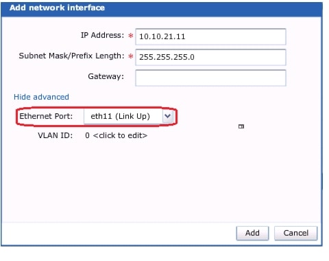
7.
Figure 69 EMC Unisphere - iSCSI Server SP-B eth11
Note
http://www.emc.com/collateral/hardware/white-papers/h8178-vnxe-storage-systems-wp.pdf
Figure 70 EMC Unisphere - iSCSI Server Settings
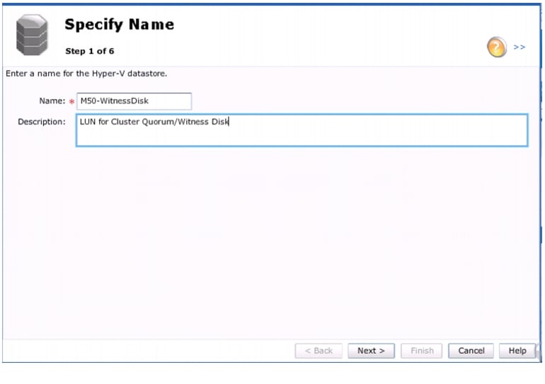
Create Hyper-V Datastores
1.
2.
Figure 71 EMC Unisphere - Specify Name in Hyper-V Storage Wizard
3.
Note
Figure 72 EMC Unisphere - Configure Storage in Hyper-V Storage Wizard
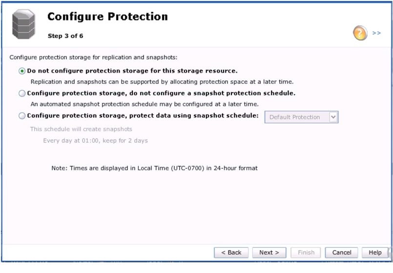
4.
Figure 73 EMC Unisphere - Configure Protection in Hyper-V Storage Wizard
5.
6.
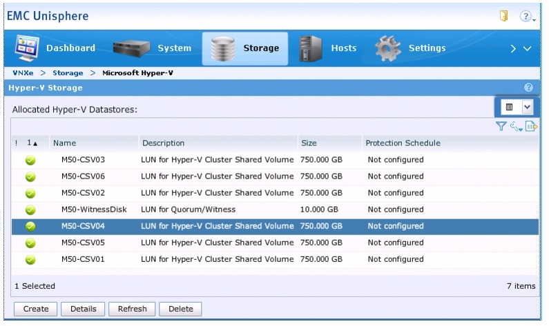
Note
Figure 74 Hyper-V Datastores on VNXe3150 for Cluster Shared Volume
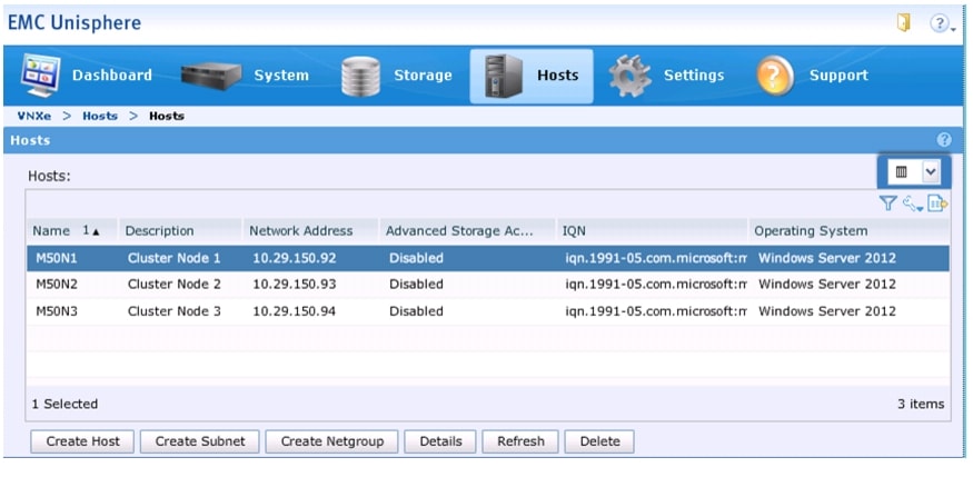
Create Hosts and Provide Host Access
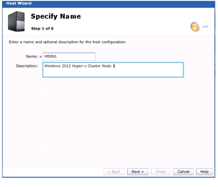
1.
2.
Figure 75 Specify Name in the VNXe Host Wizard
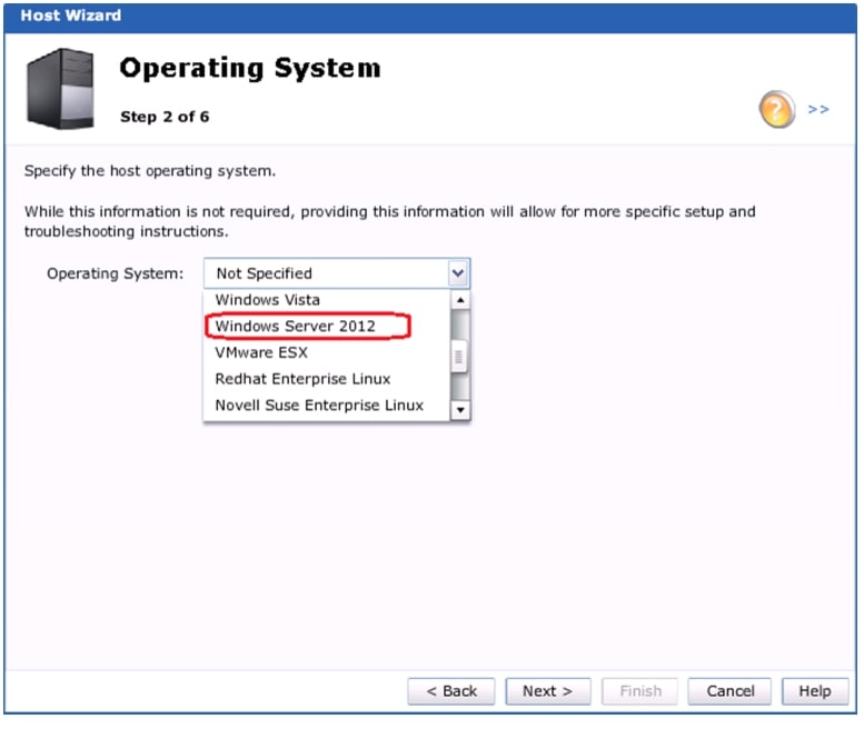
3.
Figure 76 Operating System Page in VNXe Host Wizard
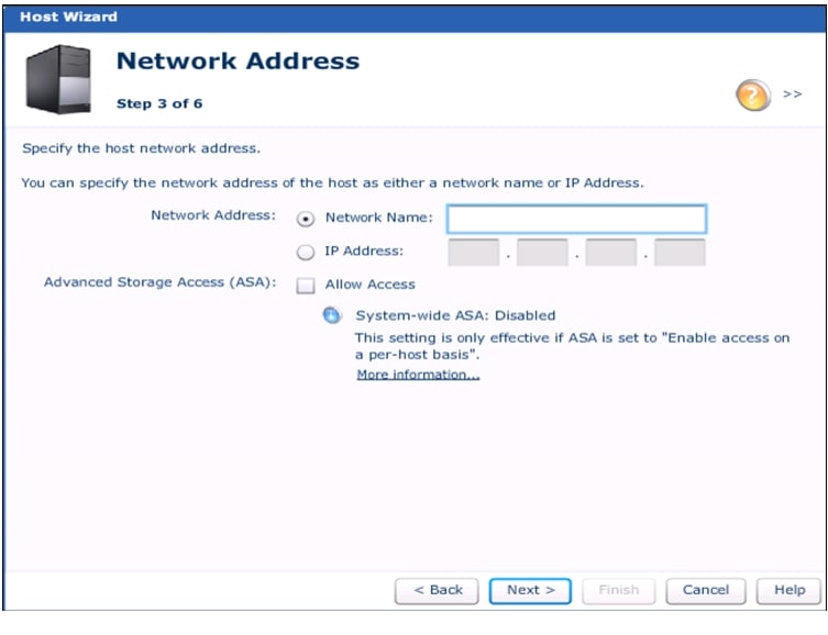
4.
Figure 77 Network Address Page in VNXe Host Wizard
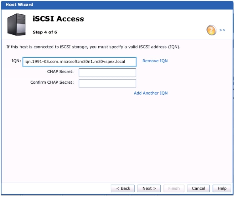
5.
Figure 78 iSCSI Access Page in VNXe Host Wizard
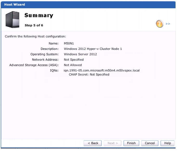
6.
Figure 79 Summary Page in VNXe Host Wizard
7.
Figure 80 VNXe Hosts Page
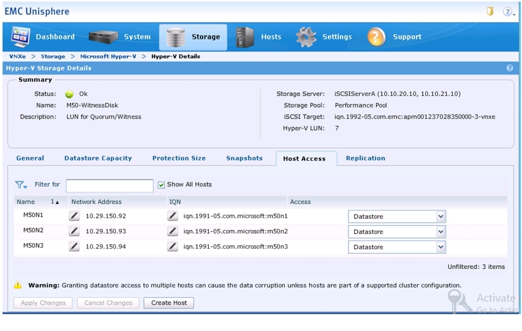
8.
9.
Figure 81 VNXe Hyper-V Datastore Details
10.
Microsoft Windows Failover Cluster Setup
Configure MPIO on Windows Server 2012
1.
2.
Enable-MSDSMAutomaticClaim -BusType iSCSI3.
Set-MSDSMGlobalDefaultLoadBalancePolicy -Policy RR4.
New-MSDSMSupportedHW -Vendor "EMC" -ProductId "Celerra"
Note
5.
Restart-ComputerConfigure iSCSI Initiator
Following steps will show how to configure the iSCSI connections to the VNXe via the iSCSI Initiator Properties GUI. The appendix also includes a PowerShell script that can be used to accomplish the same task.
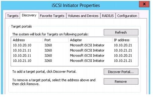
This section describes the steps to configure the host iSCSI initiator to connect to the targets. The host will look for targets on the following portals:
Follow these steps on all the hosts to connect to iSCSI targets and configure advanced settings:
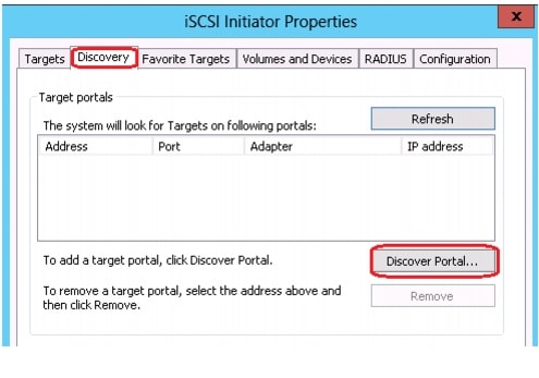
1.
2.
3.
Figure 82 iSCSI Initiator properties - Discovery
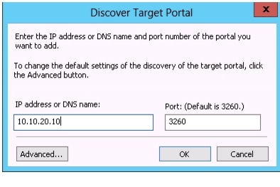
4.
Figure 83 Discover Target Portal in iSCSI Initiator Properties
5.
a.
b.
c.
Figure 84 iSCSI Initiator Properties - Advanced Properties
6.
7.
Figure 85 iSCSI Initiator Properties - Discovery
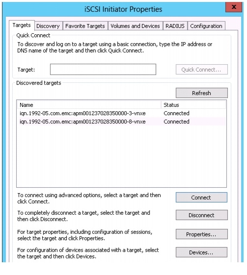
8.
Figure 86 iSCSI Initiator Properties -Targets
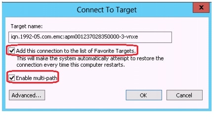
9.
a.
b.
Figure 87 iSCSI Initiator properties - Favorite Targets
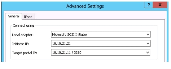
c.
d.
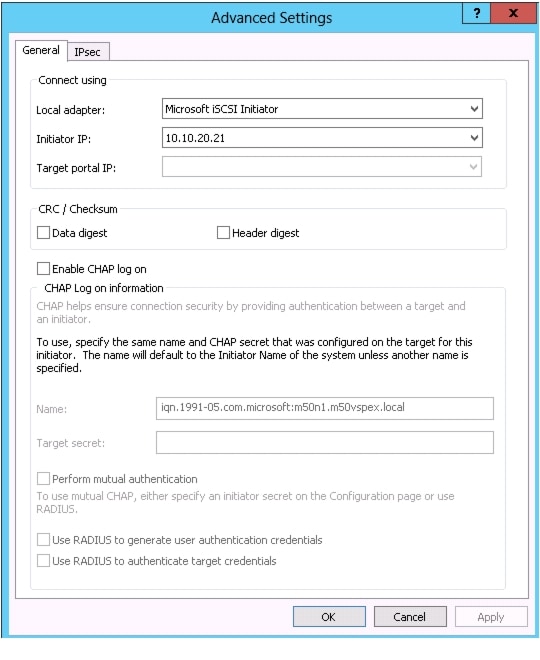
Figure 88 iSCSI Initiator Properties - Advanced Settings
10.
11.
Figure 89 iSCSI Initiator Properties - Advanced Settings
12.
Figure 90 iSCSI Initiator Properties - Discovered Targets
Figure 91 iSCSI Initiator Properties - Discovery
13.
Figure 92 PowerShell Get-iSCSIConnection
14.
mpclaim -s -d
Then choose and MPIO disk number and run:
mpclaim -s -d 0
Figure 93 PowerShell mpclaim.exe Configuration Output
15.
Figure 94 Disk Management - Disk Offline
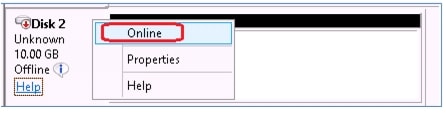
16.
Figure 95 Disk Management - Disk Online
17.
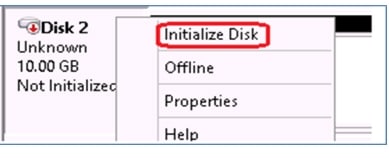
18.
Figure 96 Disk Management - Initialize Disk
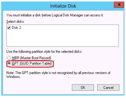
19.
Figure 97 Disk Management - Initialize Disk MBR/GPT
20.
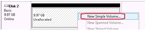
21.
Figure 98 Disk Management - New Simple Volume
22.
23.
24.
Figure 99 Disk Management - New Simple Volume Wizard
25.
26.
27.
28.
Figure 100 Format Partition - New Simple Volume Wizard
29.
30.
31.
32.
33.
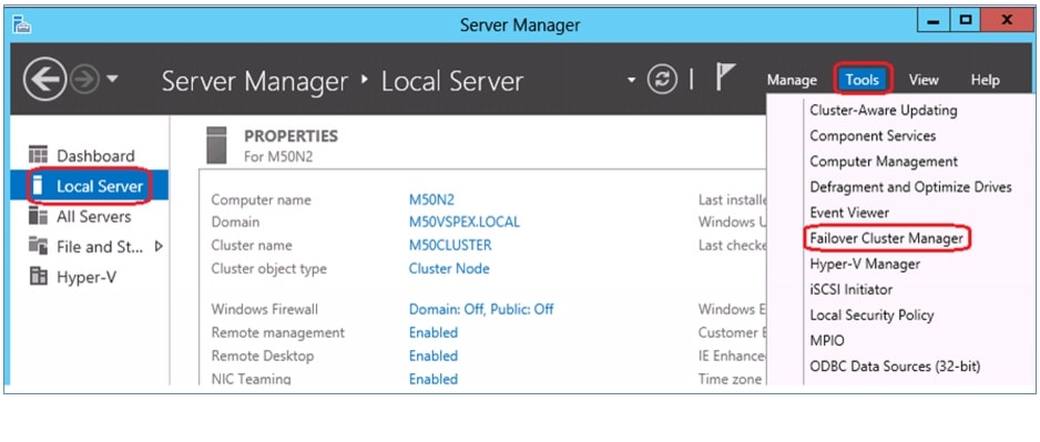
12.3 Microsoft Failover Cluster Validation1.
2.
Figure 101 Server Manager
3.
Figure 102 Failover Cluster Manager
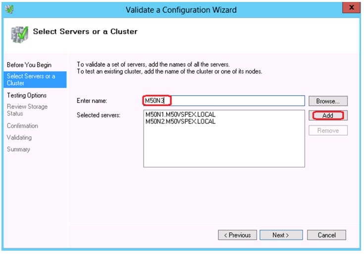
4.
5.
Figure 103 Validate a Configuration Wizard
6.
7.
Note
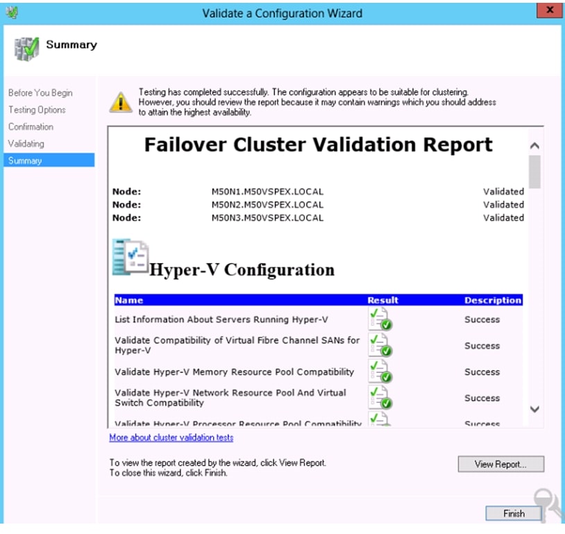
8.
9.
Figure 104 Failover Cluster Validation Report
Failover Cluster setup
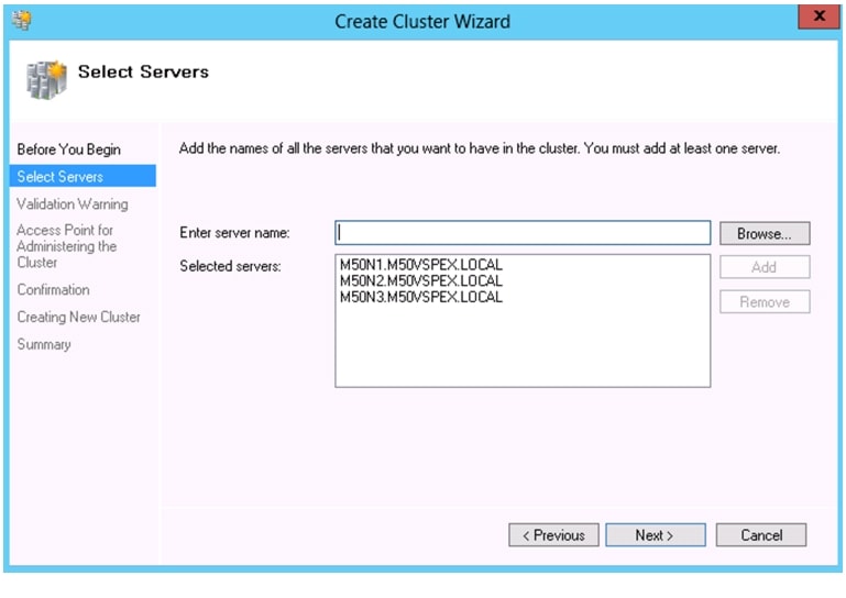
1.
2.
3.
Figure 105 Create Cluster Wizard
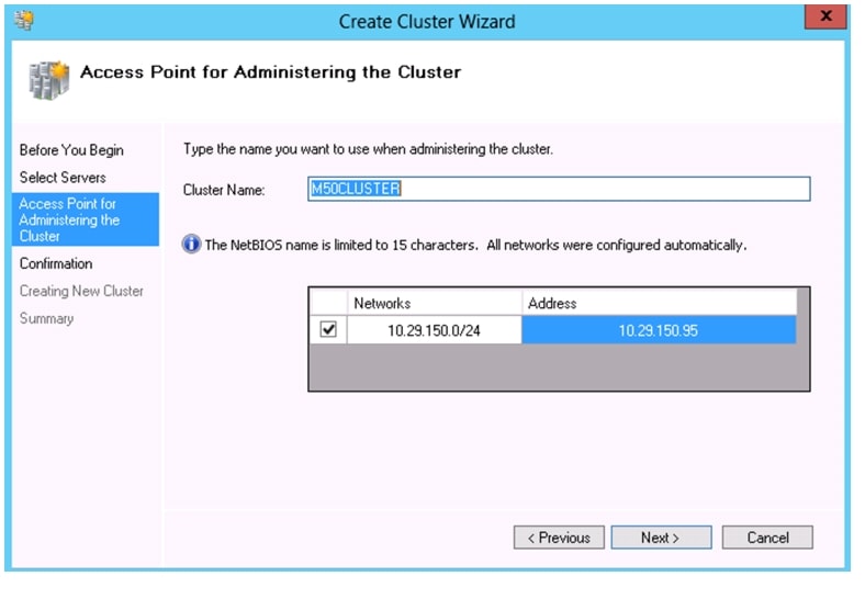
4.
5.
Figure 106 Specify Network Name and IP Address in Create Cluster Wizard
6.
Figure 107 Confirmation Page in Create Cluster Wizard
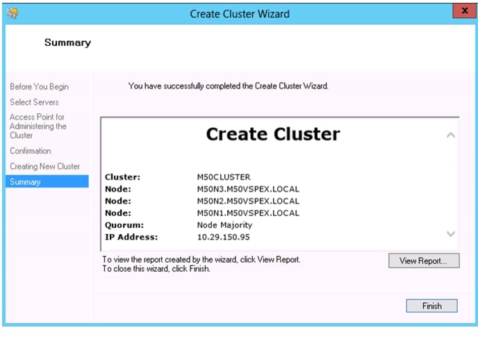
7.
Figure 108 Summary Page in Create Cluster Wizard
8.
Figure 109 Failover Cluster Manager
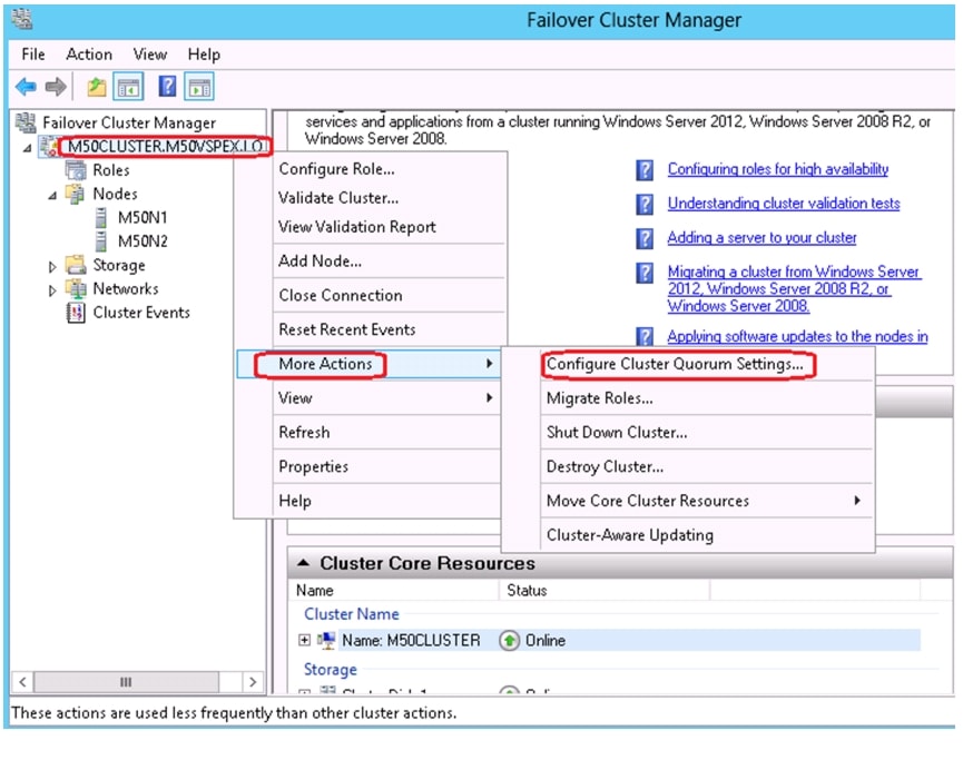
9.
10.
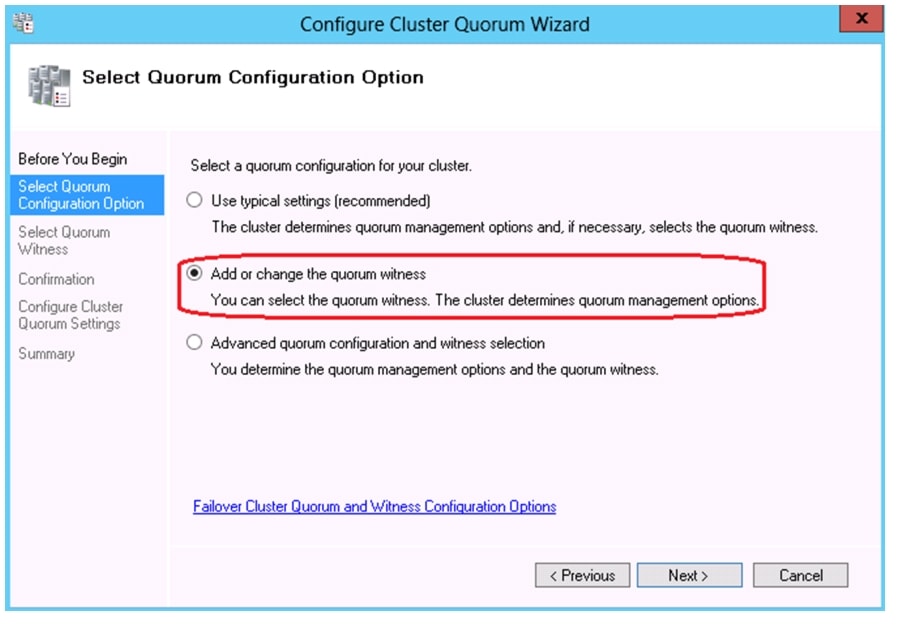
Figure 110 Select Quorum Configuration Option
11.
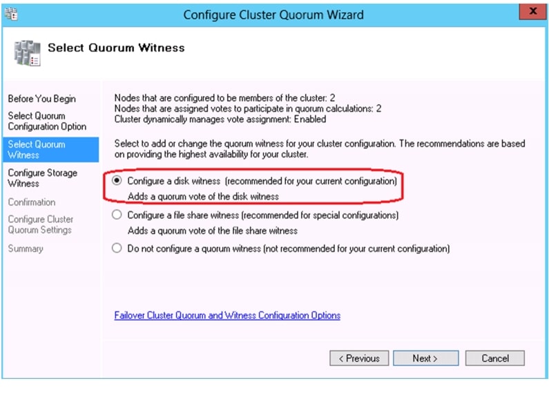
Figure 111 Configure Cluster Quorum Wizard
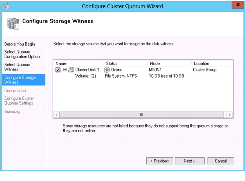
12.
Figure 112 Configure Storage Witness in Configure Cluster Quorum Wizard
13.
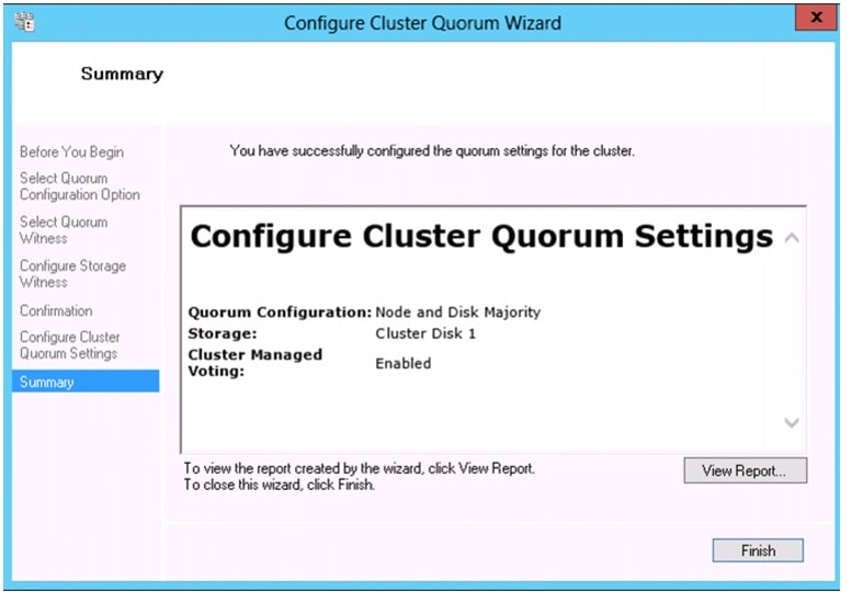
14.
Figure 113 Configure Cluster Quorum Wizard - Summary
The recomended quorum modes for even and odd nodes are:
–
–
For more information on Best Practices for configuring quorum in a failover cluster:
http://technet.microsoft.com/en-us/library/cc770620(v=ws.10).aspx
15.
16.
17.
18.
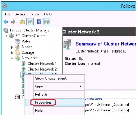
Figure 114 Rename Networks in Failover Cluster Manager
19.
Figure 115 Network Properties in Failover Cluster Manager
20.
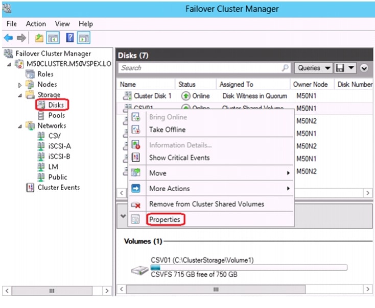
Figure 116 Failover Cluster Manager - Disks
21.
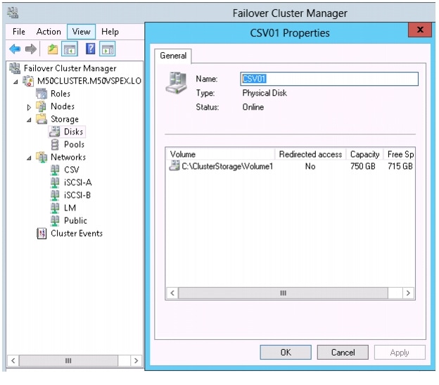
Figure 117 Failover Cluster Manager - Disks Properties
22.
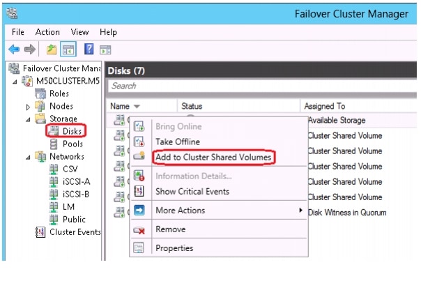
23.
Figure 118 Failover Cluster Manager - Add to CSV
24.
25.
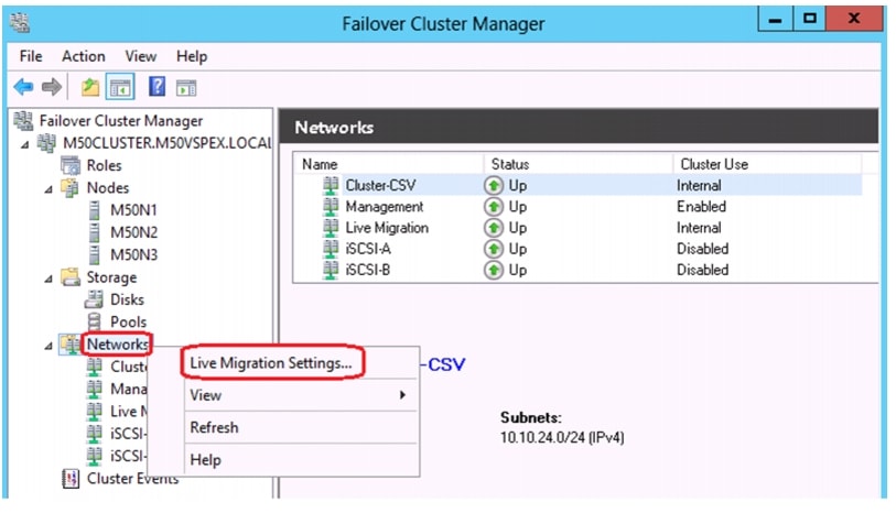
Figure 119 Failover Cluster Manager - Networks
26.
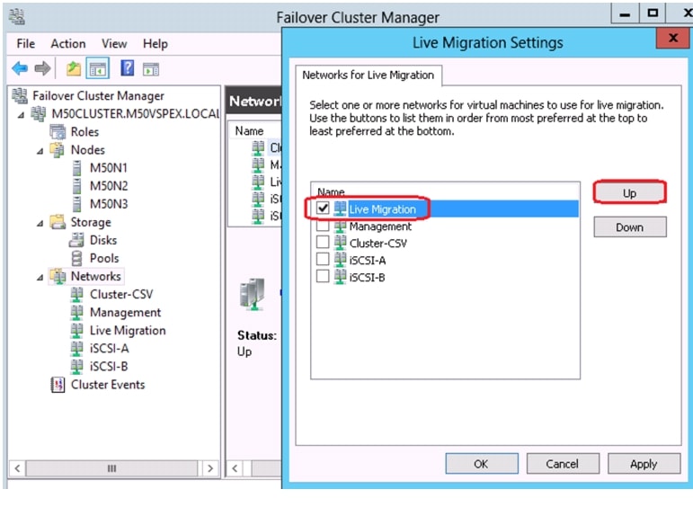
Figure 120 Failover Cluster Manager - Live Migration Settings
27.
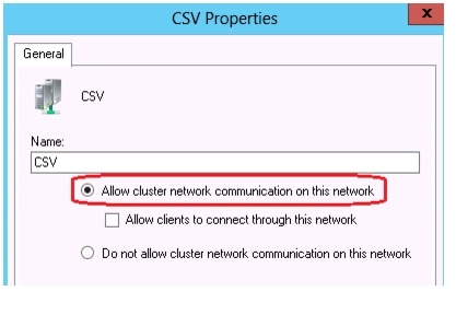
Figure 121 Failover Cluster Manager - CSV Networks Properties
28.
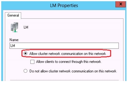
Figure 122 Failover Cluster Manager - LM Networks Properties
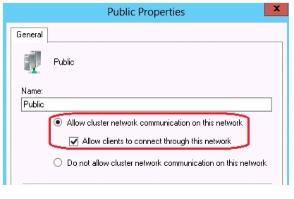
29.
Figure 123 Failover Cluster Manager - Public Networks Properties
30.
Figure 124 Failover Cluster Manager - iSCSI Networks Properties
Create Virtual Machine
This section describes how to create the first virtual machine. This first virtual machine will be turned into a template that can be used to quickly create additional virtual machines. To build the template, follow these steps:
1.
2.
3.
4.
5.
Follow these steps from one of the nodes of the cluster:
1.
Figure 125 Failover Cluster Manager - Roles
2.
3.
4.
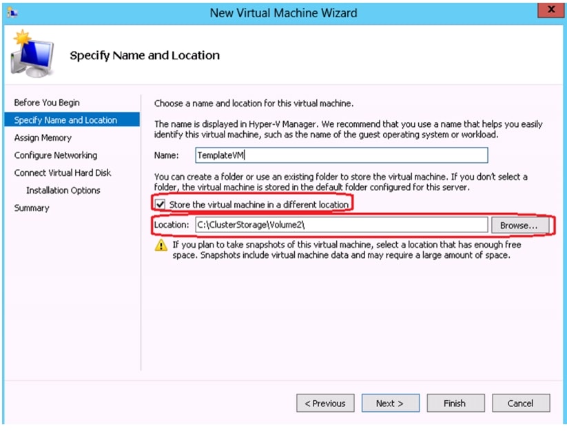
5.
Figure 126 New Virtual Machine Wizard
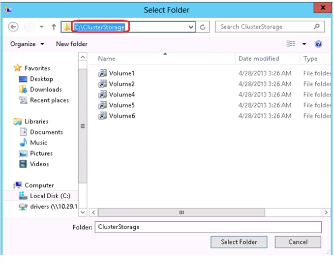
6.
Figure 127 Windows Explorer - Browse
7.
8.
9.
10.
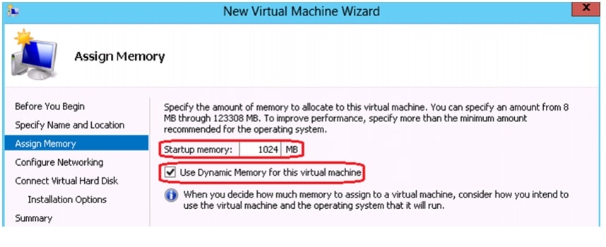
11.
Figure 128 Assign Memory in New Virtual Machine Wizard
12.
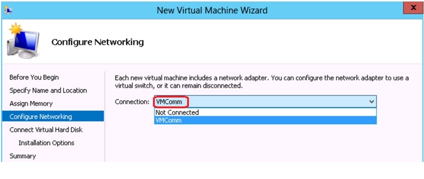
Figure 129 Configure Networking in New Virtual Machine Wizard
13.
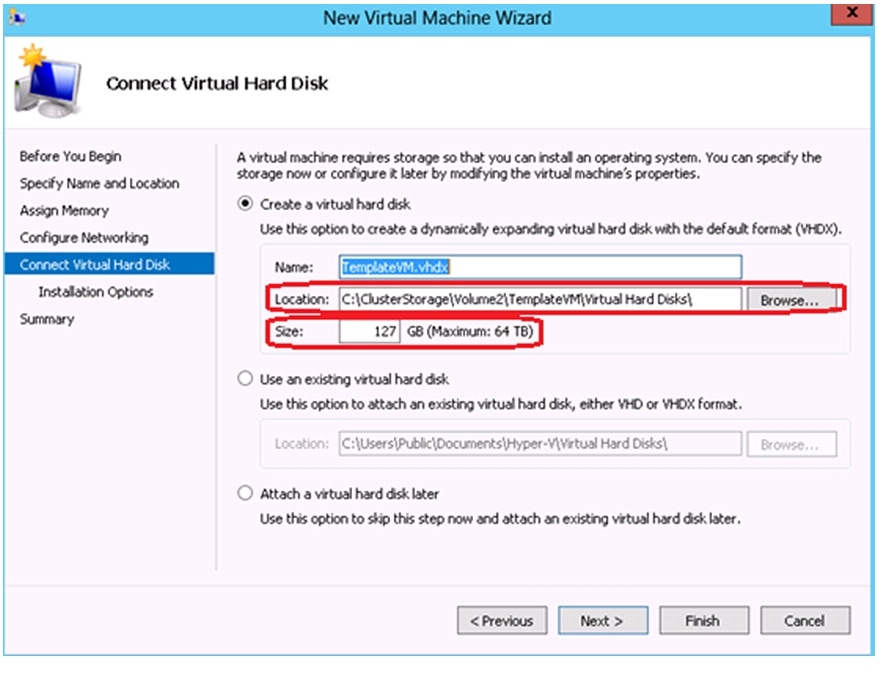
Figure 130 Connect VHD in New Virtual Machine Wizard
14.
15.
Figure 131 Installation Options in New Virtual Machine Wizard
16.
17.
18.
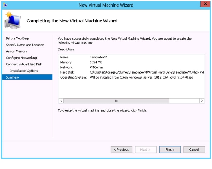
Figure 132 Summary in New Virtual Machine Wizard
19.
Figure 133 Roles in Failover Cluster Manager
20.
Figure 134 Virtual Machine Connection - Start
21.
22.
Figure 135 Virtual Machine Connection - Settings
23.
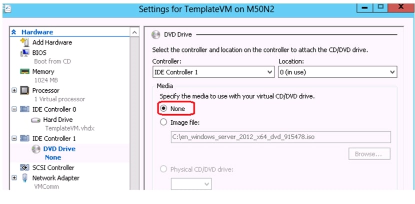
Figure 136 Virtual Machine Connection - Settings IDE Controller
24.
Figure 137 Virtual Machine Connection - Network Adapter
25.
26.
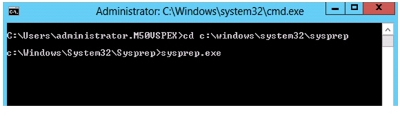
Note
Figure 138 Command Prompt - Sysprep
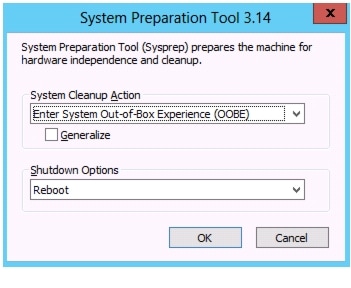
27.
Figure 139 System Preparation Tool
28.
Validating Cisco Solution for EMC VSPEX MS Hyper-V Architectures
This section provides a list of items that should be reviewed once the solution has been configured. The goal of this section is to verify the configuration and functionality of specific aspects of the solution, and ensure that the configuration supports core availability requirements.
Post Install Checklist
The following configuration items are critical to functionality of the solution, and should be verified prior to deployment into production.
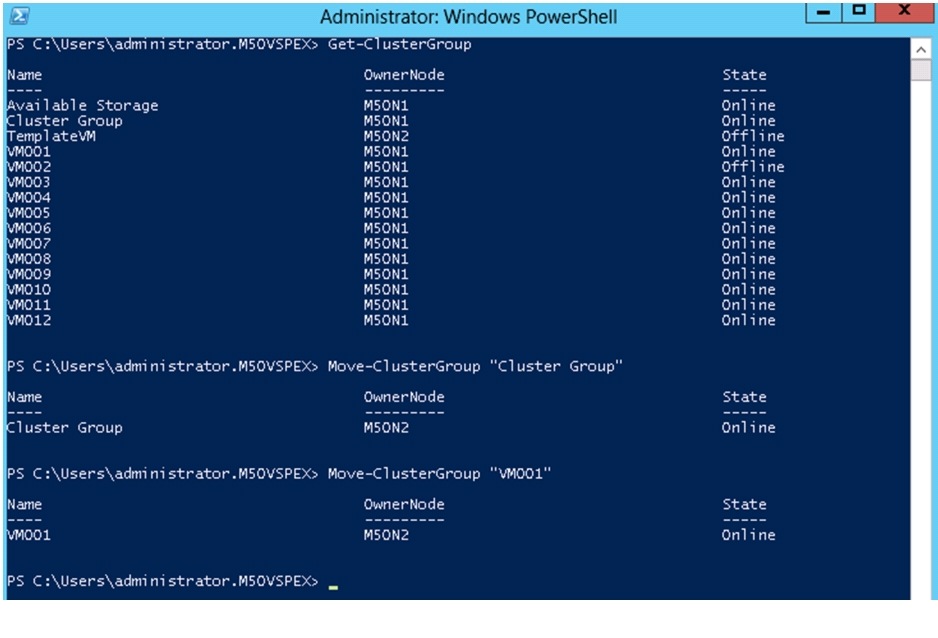
1.
Figure 140 Validation of Cluster Resources
2.
3.
4.
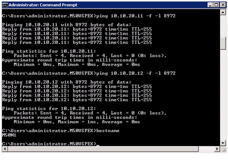
5.
Figure 141 Validation of Jumbo Frames support
6.
Figure 142 Port-Channel Summary
Verify the Redundancy of the Solution Components
Following redundancy checks were performed at the Cisco lab to verify solution robustness:
1.
2.
3.
4.
5.
Cisco validation test profile
"vdbench" testing tool was used with Windows Server 2012 to test scaling of the solution in Cisco labs. Figure 142 provides details on the test profile used.
Bill of Material
Table 13 gives details of the components used in the CVD for 50 virtual machines configuration.
For more information on the part numbers and options available for customization, see Cisco C220 M3 server specsheet at:
http://www.cisco.com/en/US/prod/collateral/ps10265/ps10493/C220M3_SFF_SpecSheet.pdf
Customer Configuration Data Sheet
Before you start the configuration, gather some customer-specific network and host configuration information. Table 14, Table 15, Table 16, Table 17, Table 18, Table 19 provide information on assembling the required network and host address, numbering, and naming information. This worksheet can also be used as a "leave behind" document for future reference.
Table 14 Common Server Information
Domain Controller
DNS Primary
DNS Secondary
DHCP
NTP
SMTP
SNMP
vCenter Console
SQL Server
Table 15 Microsoft Hyper-V Server Information
Microsoft Hyper-V Host 1
Microsoft Hyper-V Host 2
Microsoft Hyper-V Host 3
Table 16 Array Information
Admin account
Management IP
Storage pool name
Datastore name
iSCSI Server IP
Table 17 Network Infrastructure Information
Cisco Nexus 3048 Switch A
Cisco Nexus 3048 Switch B
Table 19 Service Accounts
Microsoft Windows Server administrator
Array administrator
References
Cisco UCS:
http://www.cisco.com/en/US/solutions/ns340/ns517/ns224/ns944/unified_computing.html
Cisco UCS C-Series Servers Documentation Roadmap
http://www.cisco.com/go/unifiedcomputing/c-series-doc
Cisco Nexus:
http://www.cisco.com/en/US/products/ps9441/Products_Sub_Category_Home.html
EMC VNXe3xxx series resources:
http://www.emc.com/storage/vnx/vnxe-series.htm#!resources
Network Adapter Virtualization Design (Adapter-FEX) with Cisco Nexus 5500 Switches:
Configuring Port Channels:
Configuring port-profiles:
Configuring vPCs: