Feedback
Table Of Contents
Reliability, Availability, and Serviceability (RAS)
AC Power Shelf (AC systems only)
Automatic Protection Switching
Reliability, Availability, and Serviceability (RAS)
Overview
The MGX 8250 is designed for carrier-class reliability. System components can be configured for 100 percent redundancy, and all MGX 8250 modules can be removed and reinserted without impacting service delivery or affecting the performance of other modules. Hot-standby interfaces offer optional redundancy so that if a module fails, the standby is fully online within milliseconds. Switchover to standby interfaces is nonservice-affecting for most protocols, ensuring nonstop application performance.
The MGX 8250 Edge Concentrator supports industry-standard, automatic protection switching (APS) for all SONET and synchronous digital hierarchy (SDH) interfaces using the 1+1 APS scheme. In the event of a fiber cut or card failure, APS performs switching to the backup fiber within milliseconds. The MGX 8250 provides 1:N redundancy of service interfaces to enhance overall reliability and availability. With support for 1:N redundancy, a single standby Service Module will automatically take over the traffic functions of any failed Service Module of the same type within seconds.
The same connection routing algorithm that automatically reroutes virtual circuits in a BPX 8680/MGX 8250 network is incorporated in Cisco network modeling software. This enables the design of highly reliable networks that can withstand almost any combination of possible link failures. Nonservice-affecting software upgrades enable you to gracefully upgrade software or add new features without disrupting services. Customers receive the benefits of new features without interrupting service delivery or application performance.
Key Availability Features
The MGX 8250 supports the following Reliability, Availability, and Serviceability (RAS) features:
•
PXM/SRM hot standby and hitless redundancy
•
•
•
•
•
•
•
•
•
Redundancy
The Service Resource Module (SRM) enables 1:1 or 1:N redundancy for the Service Modules. It also offers other features, such as BERT testing and M13 grooming of circuits. There are four SRMs per node—two per shelf. The two on the top shelf service the upper service bay; the two on the bottom service the lower service bay. The SRMs are 1:1 redundant; two SRMs (one on each subshelf) are active, the other two are in standby.
The SRMs on the upper service bay support 1:N redundancy (up to 1:11 Service Module redundancy coverage through the redundancy bus) on the upper service bay. The SRMs on the lower service bay support 1:N redundancy (up to 1:N Service Module redundancy coverage through the redundancy bus).
For bulk distribution, each bay can support three channelized T3s using the SRMs. The SRM can support 80 T1/E1s per shelf. Each MGX 8250 chassis can support a total of 160 DS1s. Bulk distribution operates across ten slots. Bulk distribution is not currently supported in slots 9, 10, and 25, 26.
The SRMs can be used in conjunction with native T1/E1 Service Modules to bring the total to 192 DS1s: 160 DS1s use twenty 8-port cards and the SRMs, and 32 DS1s use four 8-port cards with T1/E1 back cards. The SRM, however, is limited to 80 DS1s across the three T3s on each SRM, for a total of 160 DS1s.
In a standard configuration, shown in Figure 9-1, the SRMs reside in chassis slots 15, 16, 31, and 32. The active SRM associates to the active processor switch module (PXM). The SRMs in slots 15 and 31 associate to the PMX in slot 7. The SRMs in slots 16 and 32 associates to PXM in slot 8. Either SRM in slot 15 or 16 can be active (depending on the active PXM).
For redundancy, the MGX 8250 power supply tray has two options—one AC cord or two AC cords.
MGX-AC1-1 is for systems requiring a single AC power supply that is powered from a single AC power source. MGX-AC1-1 provides up to 1200 W of load-shared redundant power. If additional power is needed, additional power supplies, providing an additional 1200 W each, can be added.
One AC Cord—The one-AC cord version uses 1:N power-supply redundancy. If you have three 1200W power modules, you can support up to 2400W of power; the third module is redundant. Since there is only one AC cord, you do not have redundancy for the AC cord itself.Two AC Cords—MGX-AC2-2 is for systems requiring redundant AC power supplies that will be powered from two AC power sources. The two-AC cord power tray supports 1:1 power-supply redundancy. If you have four 1200W power supplies, you can support only 2400W of power. The two AC cord power tray has two AC cords; therefore, both the AC cord and the power modules are redundant.
The quantity of AC power modules is determined by the type of power tray and by the customer's overall power requirements. The AC power module converts 220V 50/60 cycle AC into 48 VDC.
The MGX 8250 implements a robust, distributed database scheme in which the configuration parameters are stored in the Service Module local memory, active PXM hard disk, and standby PXM hard disk. This scheme ensures update efficiency and database consistency. It also includes a synchronization protocol between PXMs and SMs to recover from database inconsistency due to certain error conditions (such as switchover).
The architecture of multiple cell buses ensures that if one Service Module pulls one cell bus down, other cell buses can continue to operate without down time.
The PXM is fully redundant in a 1:1 configuration. While one of the PXMs serves as the active switching fabric, the backup serves as a hot-standby module. Upon the detection of a failure in the active PXM, the hot standby takes over the switching fabric function in a completely nondisruptive manner. The PXM1 switchover times are between 15-30 ms.
There are several signals cross-coupled between the two PXMs. If the active PXM resets, the couple signals will indicate to the standby PXM to take over mastership. Software polls the mastership logic periodically. Once it detects a hardware switchover, it will start running all the routines necessary to assume mastership.
All existing connections will be copied onto the new card—there are always exchanges between the active and standby to make sure that the standby card has all the information necessary to resume operation should the active card fail.
The T3/E3 and SONET interface ports on the Service Modules can be configured to provide a 1:1 redundancy on each Service Module. Additionally, the SRM can be configured to provide up to 1:N redundancy for the narrowband Service Modules (through the redundancy bus).
AC Power Shelf (AC systems only)
The AC power module includes the following power design features:
•
•
•
•
•
•
•
Redundancy for DC
In the DC system, the 48 VDC is supplied through either one or two power-entry modules (PEMs). The PEMs will be plugged into the midplane through the same connectors as the AC power supply. Each PEM has a circuit breaker for protection. The DC power range is from -42 to -56 VDC.
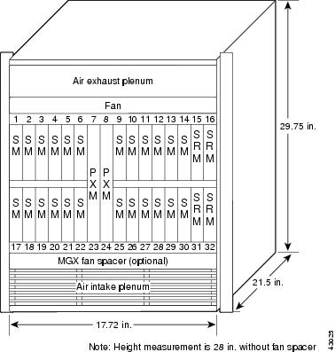
Figure 9-1 MGX 8250 Chassis
The Service Modules reside in slots 1-6, 9-14, 17-22, and 25-30. The SRM in slot 15 provides up to 1:N redundancy for the Service Modules in slots 1-6 and 9-14 and the SRM in slot 31 provides up to 1:N redundancy for the Service Modules in slots 17-22 and 25-30. The SRM in slot 16 (or 15) provides a 1:1 redundancy for the SRM in slot 15 (or 16), while the SRM in slot 32 (or 31) provides a 1:1 redundancy for the SRM in slot 31 (or 32).
Up to six 1:N redundancy groups can be supported in each subshelf.
Switchover Mechanism
The MGX 8250 backplane supports the same distribution bus employed in the MGX 8220. This is used in conjunction with the SRM-3T3 to provide M13 circuit breakout and distribution capability, as well as T1/E1 1:N Service Module redundancy (in bulk mode, the Service Modules have 1:N redundancy without using the separate T1 redundancy bus).
Nonbulk Mode Distribution
Nonbulk mode distribution is a mode of operation where individual T1 lines are directly connected to the line module of each front card. During normal nonbulk mode operation, the T1/E1 data flow is from the Service Module's line module to its front card and vice versa. The line modules also contain isolation relays that switch the physical interface signals to a common redundancy bus under SRM-3T3 control in case of Service Module failure.
If a failure is detected in nonbulk mode, the traffic destined for the failed Service Module is carried over the redundancy bus to the active SRM on its shelf. Thus, each active SRM provides redundancy for a maximum of 11 Service Modules per shelf.
When a Service Module failure is detected, the PXM will initiate a switchover to the standby Service Module. The relays on the Service Module's line module (all T1/E1s) are switched to drive the signals onto the T1 redundancy bus. The designated standby card's line module (controlled by the SRM-3T3) receives these signals on the T1/E1 redundancy bus. The data path switches from the failed Service Modules' line module to the T1/E1 redundancy bus to the line module of the standby Service Module, and finally to the standby Service Module itself.
Bulk Mode Distribution
Bulk distribution is a mode of operation in which individual lines are not brought to Service Modules, but instead these lines are multiplexed into a few high-speed lines attached to the SRM. The SRM then takes this "bulk" interface, extracts the lines, and distributes them to the Service Modules. Any cards served by this bulk interface can participate in 1:N redundancy without using the separate redundancy bus. Any T1 in a T3 line can be distributed to any eight ports on a Service Module in any slots of the service bay without restriction.
During bulk mode operation, the SRM-3T3/B unbundles T1 data from the incoming T3s and sends it to each Service Module. Any slot can be used to process T1 data or to house a standby Service Module. When a Service Module fails, the PXM will initiate a switchover to the previously configured standby module. The SRM-3T3/B will then redirect the recovered T1 traffic to the designated standby module. The switching takes place inside the SRM-3T3/B and requires no special back cards or cabling. The data path to the standby module is still via the distribution bus; the redundancy bus is NOT used in bulk mode.
Hot Standby
The switching fabric is configured in a 1:1 redundancy. Of the two PXMs in the edge concentrator, one PXM serves as the active switch fabric while the other serves as a hot standby for the active PXM. Switching Service Modules can be done in a nondisruptive manner.
Software Upgrades
Nonservice-affecting software upgrades enable the system to gracefully upgrade software or add new features without disrupting services. Customers receive the benefits of new features without interrupting service delivery or application performance.
Logical Connections
All the narrowband Service Modules are connected logically to the PXM and the SRM via the cell bus. Therefore, the failure of any single Service Module does not impact other interface cards.
Performance
The MGX 8250 availability performance is 99.999%. The primary RAS measure for the MGX 8250 product is "minutes of connection outage." The percentage of time the system or features are available for customer use is usually measured as a percentage: 99.999% (equivalent to 5.25 minutes of unavailability per year), which is the percentage of time that connections are available. It is also measured in defects per million (DPM) connection hours, or 10DPM = 99.999%
Automatic Protection Switching
Automatic Protection Switching (APS) is a means to provide redundancy on SONET equipment to guard against hardware failures. There are three modes of APS defined in GR-253 and ITU-T G.783: APS 1+1, APS 1:1, and APS 1:N. All three modes require that after any failures have been detected, switching from the working equipment to the protection equipment must be initiated in 10 ms and completed in 50 ms (for a total of 60 ms).
In an APS 1+1 implementation, a redundant protection line exists for every working line. Traffic protected by the redundancy is carried simultaneously by the working and protection lines. The receiver terminating the APS 1+1 must select cells from either the working or protection line and be able to forward one consistent traffic stream. Both working and protection lines transmit identical information; therefore, the receiving ends can switch from one to the other without coordination with the transmit end. If the working (or active) fiber optic cable fails, the protection fiber is selected at the SONET layer. In full compliance with the standards, the K1 and K2 bytes are utilized for this signaling.
The cross-coupling between adjacent slots permits APS 1+1redundancy. If a link failure, the main processor subsystemcontrolling the PXM switches from the failing port to the backup port. The processor performs this function intelligently based on the alarm status. The backplane provides the cross-coupled traces between slots 7 and 8.