Feedback
Table Of Contents
Configurable Traffic Parameters
Configuring Traffic Descriptors
Policing Using ATM Forum Standards
Policing Provisioned Point-to-Point Virtual Circuits
Service Module Policing Function
Circuit Emulation Service Module
Processor Switch Module (PXM-1)
VI and COS Queues Architecture
Traffic Management
MGX 8250 traffic management features are designed to minimize congestion while maximizing the efficiency of traffic routing. Parameters such as minimum cell rate (MCR), committed information rate (CIR), committed port rate (CPR), and committed delivery rate (CDR) provide deterministic performance and fairness for each VC and for each service class.
The MGX 8250 platform reserves queues specifically for IP traffic, and uses queuing and prioritizing algorithms to enhance the standard CoS offerings, which include:
•
Class of service (CoS) support (hardware support for 16 CoS, firmware support for CBR, VBR-RT, VBR-NRT, ABR-FS, ABR-STD, UBR)
•
•
•
•
Stamping on future releases)•
•
•
•
•
Traffic Management Functions
On the MGX 8250, the traffic management functions are performed in two separate locations:
1.
–
–
–
–
2.
The queue engine (QE) ASIC provides the traffic management functions related to VC queues, QoS queues, and interface queues. This function is performed for both directions of the traffic. The PXM-1 card can have up to four physical lines. The user can split the line resources into multiple logical ports up to a maximum of 32. The switching fabric maps each of these logical ports defined on the PXM-1 lines to what is termed a virtual interface (VI). The switching fabric also maps each Service Module slot to a virtual interface.
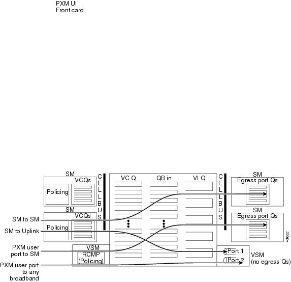
Figure 7-1 reflects functional flow of data passing through the PXM-1 switch fabric and daughter card.
Figure 7-1 PXM Switch Fabric
Ingress traffic is defined as data flowing toward the switch fabric. Ingress data can come from either the Service Modules through the backplane or the PXM 1 uplink back card.
Egress traffic is defined as data flowing away from the switch fabric.
Ingress data from Service Modules arrives at the PXM-1 via the cell bus and hits the switch fabric, where the VC and Qbin queueing occurs. The destination of this traffic defines which VI queue it will be placed into. Ingress data from the PXM-1 will first be channeled through the uplink daughter card where policing will occur. The uplink ingress data will then pass through the switching fabric and the same VC, Qbin, and VI queuing will occur.
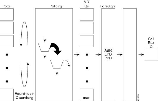
Figure 7-2 details the general traffic flow. Figure 7-3 shows the Switch Module to Switch Fabrication arbitration. Figure 7-4 shows Egress Traffic Management.
Figure 7-2 Ingress Traffic Management
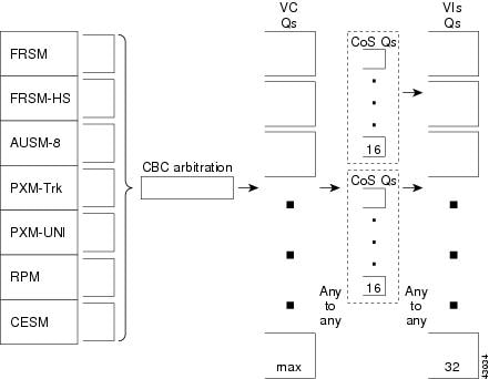
Figure 7-3 Service Module to Switch Fabric Arbitration
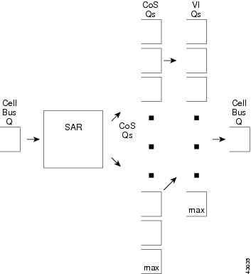
Figure 7-4 Egress Traffic Management
Configurable Traffic Parameters
There are four groups of traffic management parameters that are configured for each connection.
1.
–
pcr
scr
ibs
mbs
ingrUpcFGCRAEnable
cdvt
scrPolicingEnable
–
cir
bc
be
ibs
–
None used
–
pcr
scr
cdvt
mbs
scrPolicingEnable
2.
–
ingressQDepth
ingressClpHiThresh
ingressClpLoThresh
ingressEFCITHresh
Discard option
–
ingressQDepth
ingressQDEThresh
ingressQECNThresh
–
None used
–
None used
3.
•
•
•
•
4.
AUSM/B
–
–
–
–
–
FRSM
–
–
–
CESM
–
–
VSM)
None used
Connection Admission Control
Connection Admission Control (CAC) is performed on-port in the ingress and egress directions. Port overbooking is optionally supported on both the FRSM and the AUSM/B. The CAC override function is configurable on a per-connection basis.
•
–
–
–
•
Ingress (when CAC override is off or CAC is enabled):
sum of (CIR * chanIngrPercentUtil) of all channels on the port < = port speed
Egress:
sum of (chanEgrSrvRate * chanEgrPercentUtil) of all channels on the port < = port speed
When CAC overide is ON or CAC is disabled, the load is still cumulated on the port for a channel, but it is always admitted if CIR/chanEgrSrvRate is less than port speed.
•
For the ingress rate, ingrUpcPCR01 is used for CBR/VBR and UBR, foresightMIR is used for ABR. For the egress side, the rate used is ausmChanEgrSrvRate.
•
Ingress side:
–
–
Egress side:
–
–
For the rest of the cases, CAC passes.
In case ausmChanOvrSubOvrRide is enabled, even though CAC fails, connection addition goes through.
Policing
The edge concentrator complies with the UPC policing standards as defined by the ATM Forum UNI 3.1 specifications. The following traffic descriptors are configurable on a per-connection basis:
•
•
–
–
–
–
–
•
•
–
–
–
–
–
–
Configuring Traffic Descriptors
Depending on the type of connection, the AUSM/B connection's bandwidth control parameters can be defined. For CBR and UBR connections, PCR and CDVT are specified. For VBR and ABR connections, and PCR and CDVT, SCR and BT are specified. lists the different parameters that can be defined during connection setup. It also indicates that UPC can be enabled/disabled on a per connection basis.
The pcr [0], cdvt [0] and clp_tag parameters shown above do not apply for the PXM 1 UNI ports. On the FRSM modules, the Frame Relay policing parameters are configurable per channel as shown in Table 7-2.
Policing Using ATM Forum Standards
The MGX 8250 UPC function can be configured to police incoming traffic streams on any combination of PCR (0), PCR (0+1), SCR, CDVT, and BT. For broadband interfaces, the policing is done by the RCMP chip on the trunk card. The RCMP supports two approximations to the GCRA algorithm for each connection. Per-VC policing is done to adhere to parameters negotiated at connection setup. For CBR and UBR connections, PCR and CDVT are specified. For VBR and ABR connections, in addition to PCR and CDVT, SCR and BT are specified. Policing can be done on a programmable combination of cell types: user cells, OAM cells, high or low-priority cells, or RM cells.
The MGX 8250 provides a selective cell-discard function (distinguishing high-priority cells over low-priority cells) that can be utilized for all QoS classes except those associated with the constant bit rate (CBR) service class.
During connection setup, the action taken on a non-conforming cell can be programmed on a per-VC basis:
•
•
•
•
For CBR and UBR connections, only one policing instance (GCRA-1) is needed to check for PCR and CDVT conformance. For VBR and ABR connections, one policing instance (GCRA-1) is needed to check for PCR, CDVT conformance, and another instance (GCRA-2) for SCR, BT conformance. Frame discard features are supported in the queue engine.
Policing features supported by the different Service Modules are summarized in Table 7-3.
Policing Provisioned Point-to-Point Virtual Circuits
The granularity of the PCR is defined by the sampling rate of the policing algorithm. Table 7-4 lists the minimum PCR and maximum CDVT parameters for the available sampling rates on PXM1.
Service Module Policing Function
The MGX 8250 provides the a policing function for each type of service module.
Frame Service Module (FRSM)
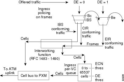
The policing function for the FRSM cards is based on a dual leaky bucket operation. The first bucket checks for compliance with the burst Bc, and the second bucket checks for compliance with the burst Be. The policing function in the FRSM measures the incoming traffic average rate over a period "T." It then decides if the traffic should be:
•
•
•
•
•
•
•
•
The policing mechanism differs slightly between the lower speed FRSM cards (FRSM-8T1/8E1/8-T1-C/8-E1-C/HS1/B) and the higher speed FRSM cards (FRSM-HS2/2CT3/2T3E3).
The overall dual leaky bucket algorithm is used for both types of cards, but there are a few differences regarding limits, the credit scheme, and the IBS function as described below:
•
•
•
For the lower speed FRSMs, if the amount of credit accumulated is less than the IBS value (which is user configurable), then the frame was marked for a separate IBS queue.•
Figure 7-5 shows the ingress cell flow on the FRSMs.
Figure 7-5 Ingress Cell Flow
For FRSM modules, the F-GCRA feature is not available at the UPC policing point.
ATM Service Module (AUSM/B)
The UPC in AUSM/B can be configured to run either a frame-based generic cell rate algorithm (FGCRA) or the GCRA defined in ATM UNI3.0. In case of FGCRA, at the arrival of the first cell of the frame, the bucket depth is compared with a limit parameter (for example, L1). If the first cell is noncompliant, then all the remaining cells in the frame will be treated as noncompliant. If the first cell is compliant, then the remaining cells will be compliant if the depth of the bucket upon cell arrival is less than or equal to a limit parameter (for example, L2).
Once the cell has passed through UPC, it will be queued onto the ingress queue after the following checks:
1.
2.
3.
4.
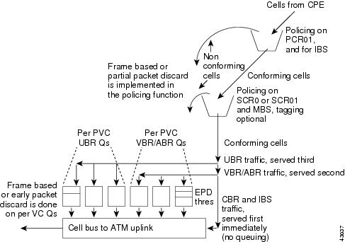
In addition to the FGCRA algorithms provided by the AUSM/B, there is an EPD/PPD feature available in QE. This is enabled on a per-connection basis. Figure 7-6 shows the ingress flow on the AUSM/Bs.
Figure 7-6 Ingress Flow on an AUSM/B
Figure 7-7 and Figure 7-8 show the policing for the different types of traffic.
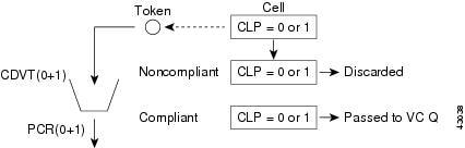
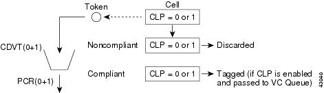
Figure 7-7 AUSM Traffic Policing for CBR
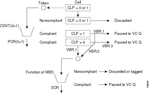
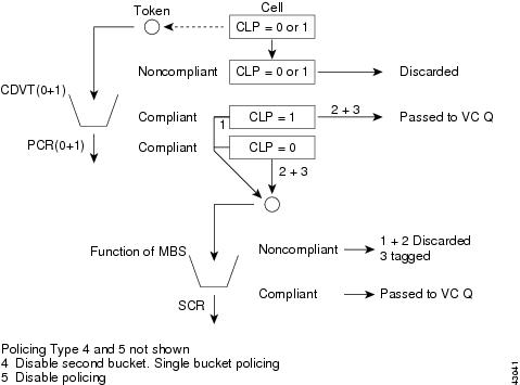
Figure 7-8 AUSM Traffic Policing for VBR
Table 7-5 summarizes the UPC actions based on the type of policing selected for VBR traffic.
Figure 7-9 AUSM Traffic Policing for ABR
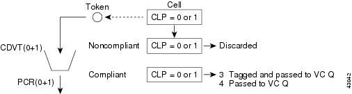
Figure 7-10 AUSM Traffic Policing for UBR
Processor Switch Module
The broadband line daughter card polices data from broadband ports configured as user ports. UPC is performed on a per-channel basis. Figure 7-11, Figure 7-12, and Figure 7-13 show the policing for the different types of traffic.
Figure 7-11 PXMTraffic Policing for CBR
Figure 7-12 PXM Traffic Policing for VBR
Figure 7-13 PXM Traffic Policing for ABR
Figure 7-14 PXM Traffic Policing for UBR
Table 7-6 summarizes the UPC actions based on the type of policing selected for VBR traffic.
Table 7-7 summarizes the UPC actions based on the type of policing selected for UBR traffic:
QoS and Buffer Architecture
The QoS classes provisioned on a per-connection basis in MGX 8250 modules are as follows:
•
•
•
•
•
The MGX 8250 can isolate the different Quality of Service (QoS) traffic streams within each logical interface connecting to the switch fabric so that it has a separate set of Qbins. Each set consists of a Qbin for each distinct Class of Service (CoS) (CBR, VBR-RT, VBR-NRT, standard ABR, ForeSight ABR, UBR). All the cells on all connections of a given CoS are queued into the Qbin for that CoS. The servicing of the Qbins for each interface is based on the minimal service rate and the relative priority between all CoSs.
The MGX 8250 provides up to 16 QoS queues for each virtual interface.
VC queue (VCQ) parameters are defaulted based on service type. The MGX 8250 switch fabric has egress per-VC queues feeding CoS queues. The per-VCQ have a set of parameters that can be set to define which per VCQ get admitted into the CoS queues first. The configurable VCQ parameters are:
•
•
•
•
•
Each Service Module has cell-buffering capability in the ingress direction to the network. There is also buffering at each interface inthe egress direction.
Frame Service Module
For the Frame Service Module (FRSM) cards the buffer size is as follows:
•
–
–
•
–
–
Ingress Queuing
All conforming frames in a VC queue are serviced based on the VC's configured CIR. The CIR measurement is done by monitoring Committed Burst (BC), during a burst duration, Tc. If more than Bc bytes of traffic are received within the Tc interval, the arrival rate is considered to exceed CIR.
The per-VC queuing differs slightly for the high-speed FRSM cards and the lower speed FRSM cards.
High-speed FRSM Cards
The high-speed FRSM group includes the FRSM-HS2, FRSM-2CT3, and the FRSM-2T3E3. In the ingress direction, there are five different classes of service—CBR, rt-VBR, nrt-VBR, ABR, and UBR.
Lower Speed FRSM Cards
The low-speed FRSM group includes the FRSM-8T1/8E1/8T1-C/8E1-C/HS1/B cards. In the ingress direction, different CoSs are not supported for per-VC queuing.
Figure 7-15 shows the per-VC queuing on the FRSM cards.
Figure 7-15 Per-VC Queuing on FRSM Cards
Egress Queuing
ATM-like CoS queues have been introduced on the high-speed FRSM cards (FRSM-HS2/2CT3/2T3E3). There are four data queues:
•
•
•
•
The lower speed FRSM cards (FRSM-8T1/8E1/8T1-C/8E1-C/HS1/B) have no ATM-like CoS egress queuing mechanism. These cards have two levels of priority for data traffic—a high-priority queue and a low-priority queue. Queue is determined based upon connection type. In case of two queues, high-priority and VBR-RT connections are assigned to a high-priority queue, and VBR-NRT, ABR, and UBR are assigned to a low-priority queue.
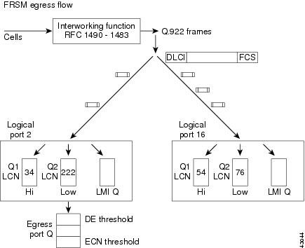
For every N times that the high-priority queue is serviced, the low-priority queue is serviced once. N is a user-configurable parameter. There is also a separate queue for LMI traffic.
For the high-speed FRSM cards (FRSM-HS2/2CT3/2TE3) in the egress direction, there is multiple-priority-level queuing per logical port. Four data egress queues and one LMI queue are maintained. There are four egress data queues:
•
•
•
•
The egress CoS mechanism implemented in the high-speed cards is based on an ATM OptiClass algorithm (algorithm 3). This is the first time that an ATM-like CoS has been introduced in a frame-Service Module. It is implemented in two stages:
•
•
In the second stage described above, the service algorithm uses a weighted-fair-queue mechanism to guarantee different classes of service. The "weight" is determined by the number of credits (or bandwidth increments) accumulated. The credits (or bandwidth increments) are automatically computed from the CIR/MIR of all connections mapped to a particular queue during channel provisioning. Every time a new connection is added or deleted, the credit/bandwidth increment must be recomputed. Port queue thresholds are also introduced in addition to per-channel level thresholds:
–
–
–
Frames are dropped when either the channel threshold or the port queue threshold is exceeded. The credit/bandwidth increment on high-speed cards is important because it determines which queue will be serviced.
The formula to determine the credit for the connection is
Credit/Bandwidth Increment = (Total CIR for connection type/Port speed) * Scaling Factor
(where the Scaling Factor is 214 or 16384).
Figure 7-16 shows the egress traffic flow for the lower speed FRSM Service Modules.
Figure 7-16 FRSM Egress Flow
In summary, the traffic flow on the FRSM cards is as follows.
Ingress Flow
The frame enters from the physical interface.
Initial Processing—For the high-speed FRSM cards, the first 32 bytes are sent to the Ingress Service Engine (ISE) for processing. The frame header is read and the ISE first determines whether the frame is an LMI frame, an SVC frame, or neither type (a "data" frame).
•
•
•
Policing—The dual leaky bucket algorithm is used to determine how frames are admitted to the network.
•
•
•
•
Interworking—The necessary interworking functions as based on FRF.5 (Network Interworking) or FRF.8 (Service Interworking) are performed.
IBS—This function is supported on a per-VC basis to favor connections that are silent for a long time. For lower speed FRSM cards, this function is linked to policing. If the credit accumulated exceeds the IBS value, the frame is marked for IBS. On the high-speed FRSM cards, the ISE checks if a frame qualifies for IBS function. If the connection has been silent for more than the "QIR Timeout" amount of time, then an "IBS" number of bytes is transferred at a line rate with increased priority to transfer this data ahead of other connections. When "IBS" number of bytes are transmitted, the IR and priority of the connection are reset to their original values.
Per-VC queuing—Traffic arriving at the network on a connection has its own dynamically assigned buffer at the entrance to the edge concentrator based on the amount of traffic and on the service-level agreement (SLA).
Segmentation—The segmentation and reassembly engine (SAR) segments the frame into cells.
Egress Flow
The frame arrives from the cell bus and moves toward the physical interface.
Initial Processing—The cell arrives from the cell bus and is delivered to the SAR Engine. The SAR uses the cell header to find the LCN/PTI.
If the cell is an OAM cell (PTI>=4), it is then sent to the OAM-receive queue, destined for the OAM module on the control processor.
If the cell is a management cell (reserved LCNs of 0-15), then the cell is sent to the management-receive queue, destined for the SCM module on the control processor.
If the cell is neither type (a "data" cell), then the cell is sent to the data-receive queue.
Reassembly—The frame is reassembled from the cell.
Queuing—While queuing the frame, if DE=1 and the queue depth of the logical port queue is > DE threshold, then the frame is discarded. At this point, FECN and BECN are updated for the outgoing frame by comparing the queue depth of the corresponding Ingress/Egress queue with the QECN threshold.
For the lower speed FRSM cards, there are two egress data queues—high and low priority. Traffic is queued up based on how the connection was configured. The high-priority queue is serviced N times for every one time that the low-priority queue is serviced.
For the high-speed FRSM cards:
•
•
–
–
–
–
•
•
ATM Service Module (AUSM/B)
For the AUSMT1/E1 cards the ingress/egress buffer size is 16K cells.
Ingress Queuing
For each connection, a VC queue buffers the cells after they are policed and before they are sent to the cell bus. The purpose of the VC queue is to manage the traffic as it moves from the AUSM/B to the PXM-1 on the shelf. The VC queue has the additional function of shaping the ingress traffic on the ABR channels.
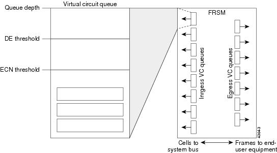
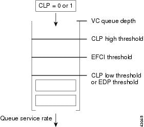
The VC queue has several thresholds associated with it to mark and respond to congestion. The EFCI threshold defines the point where the MGX concentrator will tag incoming cells with the EFCI bit. The CLP high and low thresholds determine when CLP tagged cells (CLP=1) are discarded in the VC queue if CLP hysteresis is enabled for the connection (cnfchanq command). If frame-based traffic control is enabled, the EPD threshold determines when to start discarding an AAL5 frame. A connection can have only one method enabled; either CLP hysteresis or frame-based discard (EPD).
In summary, configurable VC queuing characteristics include the following:
•
•
•
•
•
Figure 7-17 shows the per-VC queuing on the AUSM/B cards.
Figure 7-17 Per-VC Queuing on the AUSM/B Card
Egress Queuing
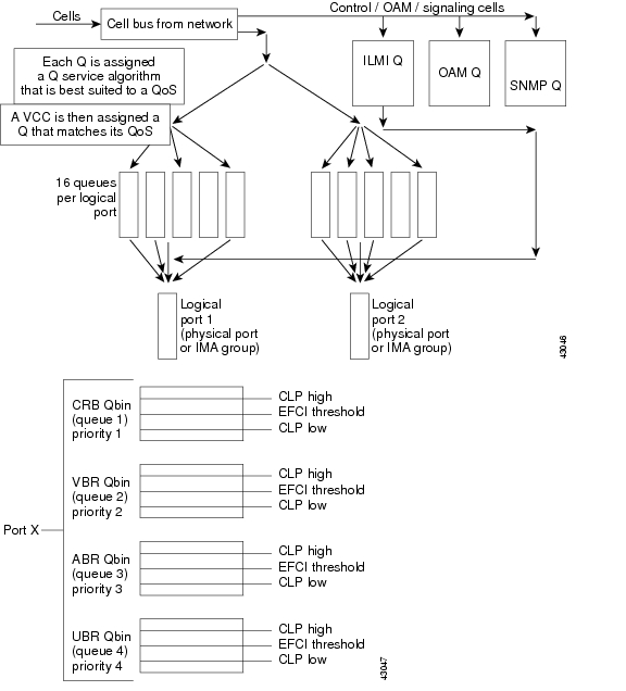
The egress port queues on the AUSM/B provide traffic management for multiple virtual circuits terminating on a single physical interface. A Qbin is a subqueue on an ATM port that buffers a specific type of traffic. For each port there is a CBR, VBR, ABR, and UBR Qbin.
Qbins are configured entering the cnfportq command. Configurable parameters include:
•
•
•
•
Figure 7-18 shows the egress traffic flow for the lower speed AUSM/B Service Modules.
Figure 7-18 AUSM/B Egress Flow
Circuit Emulation Service Module
Egress Queuing
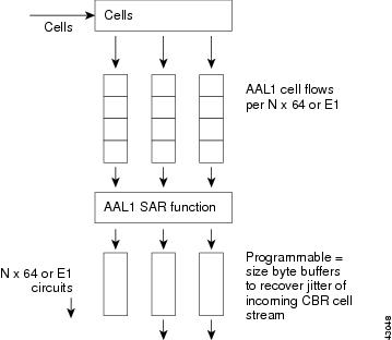
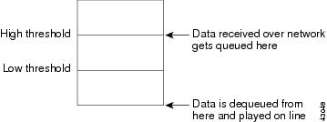
The Circuit Emulation Service Module (CESM), data received over the network is buffered before transmitting online. Buffering takes care of cell delay variation (CDV) in the network. The minimum buffering (low threshold) is a function of the CDV value specified for the channel.
The values given below are the maximum values of the buffers:
For T1 UDT and E1 UDT: 16224 bytes
For T1 SDT: 384 * N bytes
For E1 SDT: 417 * N bytes
For T3 UDT and E3 UDT: 16224 bytes (where N is the number of timeslots assigned in N x 64 connection). N = 32 for UDT connections.
The buffer size specified for a channel sets the high-threshold value. The low-threshold value decides minimum delay experienced by data and the high-threshold value decides maximum delay experienced by data. If data is not received from the network for a long time, the egress buffer runs out of data and underflow is registered. When data reception resumes, the data is buffered until the low threshold amount of data is accumulated. During underflow, dummy data (0xff) is transmitted online and underflow inserted cell count is incremented.
If data builds up in the egress buffer and crosses the high-threshold mark, an overflow event is registered. Data produced to buffer until the low mark is reached is discarded. The number of data bytes discarded during overflow is indicated by the overflow drop bytes counter.
Figure 7-19 shows the egress traffic flow for the lower speed CESM Service Modules.
Figure 7-19 CESM Egress Flow
Figure 7-20 shows the egress cell buffering on the CESM card.
Figure 7-20 CESM Egress Cell Buffer
Processor Switch Module (PXM-1)
The PXM-1 supports 256K of cell storage that is used by the QE ASICs for its queuing and buffering (128K of cell storage is allocated per direction).
In the switch fabric, there is buffering at three levels: VC queues, CoS queues, and interface queues.
The VC queue parameters are currently defaulted as follows for all connections:
•
•
•
•
When a connection is provisioned, there are two parameters that are specified for handling CLP. They are the CLP hi and CLP lo thresholds. If the queue is full when the cell arrives, the cell is discarded. If the queue is filled above CLP hi, and the incoming cell has CLP = 1, then the cell is discarded. If the queue is filled below CLP lo, then the cell is enqueued, regardless of its CLP setting. The area of the queue between CLP hi and CLP lo is called the "transition region." The transition region provides hysteresis for discarding incoming cells that have CLP = 1. If the queue was filled above CLP hi but is now emptying such that it is in the transition region (but has not dropped below CLP lo), then incoming cells with CLP = 1 are still discarded until the queue drops below the CLP lo threshold. Similarly, if the queue was filled below CLP lo (but is now filling such that it is in the transition region) (but has not filled above CLP hi), then all incoming cells are enqueued, regardless of their CLP setting.
The PXM-1 card can have up to four physical lines. The user can split the line resource into multiple partitions called broadband interfaces. The maximum number of interfaces on the PXM-1 card is 32. There is a 1:1 mapping of the broadband interface to the virtual interface on the QE. The QE implements virtual interface buffers and CoS buffers. A service group (virtual interface) is defined for each physical port on a card. A service group (VI) is also defined for each virtual trunk on the card. Multiple CoS buffers (Qbins), one for each VBR-RT, VBR-NRT, CBR, ABR, and UBR, are associated with each interface. Within each VI, there are 16 CoS queues. This configuration allows multiple service types to be configured across the same physical interface and allows high-priority traffic to bypass low-priority traffic, thus guaranteeing QoS. The VI and CoS queues can be programmed with the following parameters:
•
–
–
•
–
–
–
–
–
–
–
Figure 7-21 CoS Queuing
VI and COS Queues Architecture
From topology's point of view, there are three flows:
1.
2.
3.
All the above connections topologies follow the same queuing flow on PXM 1. It is a two-stage process.
•
Based on the minimum rate of each VI (there are 32 VIs on each QE; on QE0, each slot is mapped to a VI, and on PXM 1 uplink, each VI is mapped to a virtual interface—a logical partition of a physical link), QE selects one VI it needs to service to satisfy the rate requirement.
•
Based on the Qbin MIN rate of each Qbin of the selected VI in stage 1, a Qbin is selected.
Once a Qbin is selected, the cell at the head of that Qbin queue is moved to the output queue for the physical link or slot to be transmitted.
Cells do not physically pass the VCQ. However, when a cell is being serviced, accounting is done for the VCQ threshold function.
On the PXM 1, each QE is used for both directions (ingress and egress). Ingress and egress are defined from the perspective of QE on PXM-1 whereas on the BXMs they are defined from the perspective of the backplane. With this definition, each switch path (except those terminating on the PXM-1) has an ingress segment and an egress segment.
•
•
Separate queues can be used to support IP QoS.
IP QoS mechanisms use the three precedence bits in the type of service (ToS) field of the IP header to indicate IP precedence. Precedence values are used within the network to implement different service classes. There can be as many service classes as there are unique values of this three-bit field. Two of these values are reserved for traffic control, leaving six unique values for assignment to service classes.
Effective coupling of IP and ATM QoS is particularly challenging because of the differing paradigms (connectionless vs. connection-oriented). However, providing a seamless QoS capability between IP and ATM is essential when ATM is used as the backbone transport infrastructure for an IP VPN. This scenario allows QoS for intranet-based IP applications to take advantage of ATM QoS capabilities. MPLS is the key to this seamless integration.
In a VPN-aware network, the label header includes a CoS field with three bits to indicate a packet service class in a label-switched network. This value may be copied from the IP header when the label is applied, or it may be explicitly set by a precedence policy on the service provider edge router. In an IP network, the CoS value is used to denote service class for each packet. When MPLS is implemented in an IP network, IP QoS capabilities are used the same way as in a traditional IP-routed network. In this case, however, service class is indicated by the CoS field in the label header instead of the IP header.
When the core of the service provider network uses the ATM label switches, additional QoS capabilities are possible; they include:
•
•
Cisco edge concentrators such as the MGX 8250 provide IP service classes in addition to the standard ATM classes. These IP classes use a class-based queuing (CBQ) mechanism to implement separate queuing for IP flows while still utilizing the OptiClass buffer management feature to manage system buffers. This scenario allows the edge concentrator to provide ATM and Frame Relay services in parallel with IP while optimally allocating buffer space for all services.
Alternatively, MPLS allows a separate label VC to be used for each precedence value to a given destination. A percentage of link bandwidth can be allocated to each class of traffic using WFQ among classes to ensure that each class receives its allocated share of the link bandwidth. With the Cisco OptiClass buffer management feature, any unused bandwidth is automatically available to other classes. It is necessary to provision the link share appropriately to provide higher QoS to the higher classes. For example, if ten percent of the offered load on a link is expected to belong to a "premium" class, then allocating 15 percent of the link to the class with WFQ will ensure low-loss, low-delay service to that class.
Congestion Control Mechanisms
The AUSM/B modules perform ForeSight_ABR functions as the closed-loop end-to-end traffic management. These mechanisms allow maximizing the link utilization and avoiding the network congestion. The PXM1 supports EFCI tagging. Network uses the EFCI bit in the ATM cell header to indicate congestion. When congested, the concentrator sets an EFCI flag. The receiver must respond with "marked" RM cells and the sender will slow down upon receiving Congestion Indication (CI) in the Backward Resource Management cell (BRM).
The AUSM/B card conforms to ForeSight as a congestion-control mechanism. The MGX 8250 is capable of taking several actions based on the congestion status of the concentrator. The actions that the MGX 8250 can take are
•
•
•
•
EFCI Bit
The different Service Modules on the MGX 8250 react to a set EFCI bit. Depending on the configuration, each Service Module can take different actions upon receiving a cell with the EFCI bit set.
The EFCI bit is used in the AUSM/B.
•
•
–
–
Table 7-8 shows the mapping that can be configured on FRSM cards.
EPD/PPD Implementation
Two types of frame discard, namely, early packet discard and random early detection, are supported for AAL5 traffic. The type of frame-discard mechanism is configurable per connection.
The QE uses an EPD feature as acceptance criteria for new AAL5 frames. This feature is also referred to as packet discard (PD) and frame-based traffic control (FBTC). Two EPD thresholds apply selective cell-discard principles to new frame acceptance criteria. EPD0 applies to all cells, while EPD1 applies only to cells with CLP=1. These are explained further as follows.
In addition to EPD, the QE implements a random early detection (RED) feature, in which full frames are randomly discarded with increasing probability as the CoS buffer's time-averaged queue length approaches its EPD threshold. It has been shown that RED improves the performance of TCP connections.
Early Packet Discard
Early Packet Discard (EPD) uses the EPD0 and EPD1 thresholds for the VCs and classes of service as the acceptance criteria for new AAL5 frames. The start-of-frame (SoF) cell is determined to be the next cell to arrive following an AAL5 end-of-frame (EoF) cell.
EPD attempts to discard entire frames. However, it is possible that a cell is discarded after one or more cells of the frame have been accepted. In this case, the remainder of the frame is discarded, except that the EoF is evaluated independently (to avoid corrupting the next new frame). This is referred to as tail packet discard. In this case, if the EoF is discarded at the end of a tail discard, the next frame is also discarded, to avoid sending a corrupted frame.
The QE allows packet-discard features to be enabled on a per-connection basis. To implement these features, the QE maintains a packet-discard state for each connection that has packet discard enabled. The purpose of maintaining the states is to differentiate between a full-packet discard and tail-packet (partial) discard. There are four packet discard states:
•
•
•
•
Transitions between the states occur only upon arrival of user data cells for the corresponding connection. When an EoF cell arrives, the state machine goes to the SoF state. If an SoF cell arrives, and its corresponding cell count exceeds its VC EPD threshold (or the CoS EPD threshold is exceeded), then the cell is discarded. There are separate EPD0 and EPD1 thresholds for the CLP(0+1) and CLP(1) SoF cells. If any SoF cell arrives, and the cell count exceeds the EPD0 threshold, the SOF (and the following frame) is discarded. However, if the SoF cell has CLP = 1, and the cell count exceeds the EPD1 threshold (which is usually programmed lower than the EPD0 threshold), then the SoF cell is also discarded in this case.
The Route Processor Module (RPM) through the Port Adapter PA-A3 can perform EDP. The shaper will drop whole packets.