Catalyst 6500 Ethernet Module Installation Guide
Bias-Free Language
The documentation set for this product strives to use bias-free language. For the purposes of this documentation set, bias-free is defined as language that does not imply discrimination based on age, disability, gender, racial identity, ethnic identity, sexual orientation, socioeconomic status, and intersectionality. Exceptions may be present in the documentation due to language that is hardcoded in the user interfaces of the product software, language used based on RFP documentation, or language that is used by a referenced third-party product. Learn more about how Cisco is using Inclusive Language.
- Updated:
- August 26, 2012
Chapter: Installing Ethernet Switching Modules
Installing Ethernet Switching Modules
This chapter describes how to safely install, remove, and verify the operation of the Ethernet switching modules in the Catalyst 6500 series switches, and it contains these sections:
•![]() Installing an Ethernet Switching Module
Installing an Ethernet Switching Module
•![]() Removing an Ethernet Switching Module
Removing an Ethernet Switching Module
•![]() Installing Pluggable Transceivers
Installing Pluggable Transceivers
•![]() Attaching the Network Interface Cables
Attaching the Network Interface Cables
•![]() What To Do After Installing Modules and Verifying Connectivity
What To Do After Installing Modules and Verifying Connectivity
Safety
Safety warnings appear throughout this publication in procedures that may harm you if performed incorrectly. A warning symbol precedes each warning statement. The warnings below are general warnings that are applicable to the entire publication.
 |
Warning |
|
Warning |
|
Warning |
|
Warning |
Installing an Ethernet Switching Module
This section describes how to safely install and verify the operation of the Ethernet switching modules.
Required Tools
These tools are required to install switching modules in the chassis:
•![]() Small flat-blade screwdriver
Small flat-blade screwdriver
•![]() No. 2 Phillips screwdriver
No. 2 Phillips screwdriver
•![]() Antistatic mat or foam pad to support an unpackaged module
Antistatic mat or foam pad to support an unpackaged module
•![]() Your own ESD-prevention equipment or the disposable grounding wrist strap included with the module
Your own ESD-prevention equipment or the disposable grounding wrist strap included with the module
Chassis Slot Filler Restrictions for WS-X68xx and WS-X69xx Modules
If you are installing one or more of the WS-X68xx or WS-X69xx modules in your chassis, the slots directly adjacent to these modules (above and below or to the left and to the right) must contain either another module or switching-module filler plates (Cisco part numbers WS-X6K-SLOT-CVR-E or SLOTBLANK-09). If either adjacent slot is unused and currently has a blank slot cover (Cisco part number WS-X6K-SLOT-CVR) installed, you must remove the blank slot cover and replace it with a switching-module filler plate for NEBS compliance.
Installing an Ethernet Switching Module

To install an Ethernet switching module in the chassis, follow these steps:
Step 1 ![]() Attach an ESD grounding strap to your wrist and to ground.
Attach an ESD grounding strap to your wrist and to ground.

Note ![]() If you are unsure about the correct way to attach an ESD grounding strap, see the "Attaching Your ESD Grounding Strap" section for instructions.
If you are unsure about the correct way to attach an ESD grounding strap, see the "Attaching Your ESD Grounding Strap" section for instructions.
Step 2 ![]() Choose a slot for the module.
Choose a slot for the module.
Note ![]() Refer to your software release notes or to Chapter 2 for any information on slot or chassis restrictions for the module that you are installing.
Refer to your software release notes or to Chapter 2 for any information on slot or chassis restrictions for the module that you are installing.
Step 3 ![]() If you are installing either a WS-X68xx or WS-X69xx module, verify that the two slots adjacent to the slot where you are installing the module have either a module installed in them or a switching-module filler plate installed (Cisco part numbers SLOTBLANK-09 or WS-X6K-SLOT-CVR-E) if either slot is unused. If either slot has a blank slot cover (Cisco part number WS-X6K-SLOT-CVR), you need to remove the blank slot cover and replace it with a switching-module filler plate for NEBS compliance.
If you are installing either a WS-X68xx or WS-X69xx module, verify that the two slots adjacent to the slot where you are installing the module have either a module installed in them or a switching-module filler plate installed (Cisco part numbers SLOTBLANK-09 or WS-X6K-SLOT-CVR-E) if either slot is unused. If either slot has a blank slot cover (Cisco part number WS-X6K-SLOT-CVR), you need to remove the blank slot cover and replace it with a switching-module filler plate for NEBS compliance.
Step 4 ![]() Verify that there is enough clearance to accommodate any interface equipment, such as pluggable transceivers, that you will install directly to the module ports. If possible, install modules between empty slots that contain only module filler plates.
Verify that there is enough clearance to accommodate any interface equipment, such as pluggable transceivers, that you will install directly to the module ports. If possible, install modules between empty slots that contain only module filler plates.
Step 5 ![]() Verify that you have adequate cable guides installed on the chassis to accept the additional network interface cables for the new module.
Verify that you have adequate cable guides installed on the chassis to accept the additional network interface cables for the new module.
Step 6 ![]() Verify that the captive installation screws are tightened on all modules installed in the chassis.
Verify that the captive installation screws are tightened on all modules installed in the chassis.
Note ![]() This action assures that the EMI gaskets on all of the modules are fully compressed in order to maximize the opening space for the new or replacement module. If the captive installation screws are loose, the EMI gaskets on the installed modules will push adjacent modules toward the open slot, reducing the opening size and making it difficult to install the module.
This action assures that the EMI gaskets on all of the modules are fully compressed in order to maximize the opening space for the new or replacement module. If the captive installation screws are loose, the EMI gaskets on the installed modules will push adjacent modules toward the open slot, reducing the opening size and making it difficult to install the module.
Step 7 ![]() Remove the module filler plate covering the selected slot by removing the two Phillips pan-head screws from the filler plate.
Remove the module filler plate covering the selected slot by removing the two Phillips pan-head screws from the filler plate.
Note ![]() If you must remove an existing module, refer to "Removing an Ethernet Switching Module" section.
If you must remove an existing module, refer to "Removing an Ethernet Switching Module" section.
Step 8 ![]() Remove the new module from its shipping packaging and from the antistatic shipping bag.
Remove the new module from its shipping packaging and from the antistatic shipping bag.
Step 9 ![]() Fully open both ejector levers on the new module. (See Figure 3-1.)
Fully open both ejector levers on the new module. (See Figure 3-1.)
Step 10 ![]() Depending on the orientation of the slots in the chassis (horizontal or vertical), perform one of the following two sets of steps:
Depending on the orientation of the slots in the chassis (horizontal or vertical), perform one of the following two sets of steps:
Chassis with horizontal slots
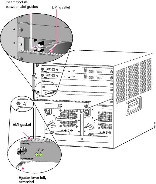
a. ![]() Position the new module in the slot. (See Figure 3-1.) Make sure that you align the sides of the module carrier with the slot guides on each side of the chassis slot.
Position the new module in the slot. (See Figure 3-1.) Make sure that you align the sides of the module carrier with the slot guides on each side of the chassis slot.
b. ![]() Carefully slide the module into the slot until the EMI gasket along the top edge of the module makes contact with the module or cover plate in the slot above it and the module ejector levers have both closed to approximately 45 degrees with respect to the module faceplate. (See Figure 3-2.)
Carefully slide the module into the slot until the EMI gasket along the top edge of the module makes contact with the module or cover plate in the slot above it and the module ejector levers have both closed to approximately 45 degrees with respect to the module faceplate. (See Figure 3-2.)
Figure 3-1 Positioning the Module in a Horizontal Slot Chassis
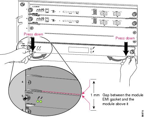
c. ![]() Using the thumb and forefinger of each hand, grasp the two ejector levers and gently press down to create a small 0.040 inch (1 mm) gap between the module's EMI gasket and the module or cover plate above it. (See Figure 3-2.)
Using the thumb and forefinger of each hand, grasp the two ejector levers and gently press down to create a small 0.040 inch (1 mm) gap between the module's EMI gasket and the module or cover plate above it. (See Figure 3-2.)
Note ![]() Do not press down too forcefully on the levers because they will bend and get damaged.
Do not press down too forcefully on the levers because they will bend and get damaged.
Figure 3-2 Clearing the EMI Gasket in a Horizontal Slot Chassis
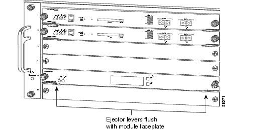
d. ![]() While gently pressing down, simultaneously close the left and right ejector levers to fully seat the module in the backplane connector. The ejector levers are fully closed when they are flush with the module faceplate. (See Figure 3-3.)
While gently pressing down, simultaneously close the left and right ejector levers to fully seat the module in the backplane connector. The ejector levers are fully closed when they are flush with the module faceplate. (See Figure 3-3.)
Note ![]() Failure to fully seat the module in the backplane connector can result in error messages.
Failure to fully seat the module in the backplane connector can result in error messages.
e. ![]() Tighten the two captive installation screws on the module.
Tighten the two captive installation screws on the module.
Note ![]() Make sure the ejector levers are fully closed before tightening the captive installation screws.
Make sure the ejector levers are fully closed before tightening the captive installation screws.
f. ![]() Verify that the module STATUS LED is lit.
Verify that the module STATUS LED is lit.
g. ![]() Periodically check the STATUS LED:
Periodically check the STATUS LED:
•![]() If the STATUS LED changes from orange to green, the module has successfully completed the boot process and is now online.
If the STATUS LED changes from orange to green, the module has successfully completed the boot process and is now online.
•![]() If the STATUS LED remains orange or turns red, the module has not successfully completed the boot process and may have encountered an error. For more information about the orange or red STATUS LED states, see the LED table for your specific module in Chapter 2.
If the STATUS LED remains orange or turns red, the module has not successfully completed the boot process and may have encountered an error. For more information about the orange or red STATUS LED states, see the LED table for your specific module in Chapter 2.
Note ![]() You should install switching-module filler plates (Cisco part number 800-00292-01) in any empty slots to maintain consistent airflow through the switch chassis.
You should install switching-module filler plates (Cisco part number 800-00292-01) in any empty slots to maintain consistent airflow through the switch chassis.
Figure 3-3 Closing the Ejector Levers in a Horizontal Slot Chassis
Chassis with vertical slots
a. ![]() Position the module in the slot. (See Figure 3-4.) Make sure that you align the sides of the switching-module carrier with the slot guides on the top and bottom of the chassis slot.
Position the module in the slot. (See Figure 3-4.) Make sure that you align the sides of the switching-module carrier with the slot guides on the top and bottom of the chassis slot.
b. ![]() Carefully slide the module into the slot until the EMI gasket along the right edge of the module makes contact with the module or cover plate in the slot adjacent to it and the module ejector levers have both closed to approximately 45 degrees with respect to the module faceplate. (See Figure 3-5.)
Carefully slide the module into the slot until the EMI gasket along the right edge of the module makes contact with the module or cover plate in the slot adjacent to it and the module ejector levers have both closed to approximately 45 degrees with respect to the module faceplate. (See Figure 3-5.)
Figure 3-4 Positioning the Module in a Vertical Slot Chassis
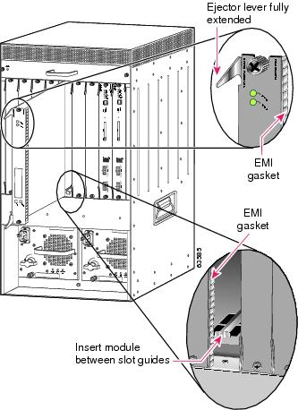
Figure 3-5 Clearing the EMI Gasket in a Vertical Slot Chassis
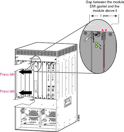
c. ![]() Using the thumb and forefinger of each hand, grasp the two ejector levers and exert a slight pressure to the left, deflecting the module approximately 0.040 inches (1 mm) creating a small gap between the module's EMI gasket and the module or cover plate adjacent to it. (See Figure 3-5.)
Using the thumb and forefinger of each hand, grasp the two ejector levers and exert a slight pressure to the left, deflecting the module approximately 0.040 inches (1 mm) creating a small gap between the module's EMI gasket and the module or cover plate adjacent to it. (See Figure 3-5.)
Note ![]() Do not exert too much pressure on the ejector levers because they will bend and get damaged.
Do not exert too much pressure on the ejector levers because they will bend and get damaged.
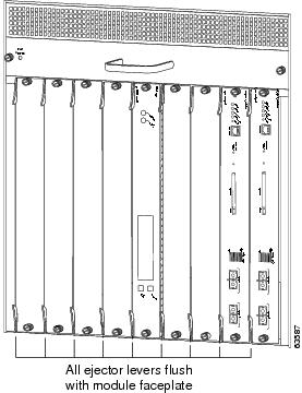
d. ![]() While gently pressing down on the ejector levers, simultaneously close both levers to fully seat the module in the backplane connector. The ejector levers are fully closed when they are flush with the module faceplate. (See Figure 3-6.)
While gently pressing down on the ejector levers, simultaneously close both levers to fully seat the module in the backplane connector. The ejector levers are fully closed when they are flush with the module faceplate. (See Figure 3-6.)
Figure 3-6 Closing the Ejector Levers in a Vertical Slot Chassis
e. ![]() Tighten the two captive installation screws on the module.
Tighten the two captive installation screws on the module.
Note ![]() Make sure that the ejector levers are fully closed before tightening the captive installation screws.
Make sure that the ejector levers are fully closed before tightening the captive installation screws.
f. ![]() Verify that the module STATUS LED is lit.
Verify that the module STATUS LED is lit.
g. ![]() Periodically check the STATUS LED:
Periodically check the STATUS LED:
•![]() If the STATUS LED changes from orange to green, the module has successfully completed the boot process and is now online.
If the STATUS LED changes from orange to green, the module has successfully completed the boot process and is now online.
•![]() If the STATUS LED remains orange or turns red, the module has not successfully completed the boot process and may have encountered an error. For more information about the orange or red STATUS LED states, see the LED table for your specific module in Chapter 2.
If the STATUS LED remains orange or turns red, the module has not successfully completed the boot process and may have encountered an error. For more information about the orange or red STATUS LED states, see the LED table for your specific module in Chapter 2.
Removing an Ethernet Switching Module
This section describes how to remove an Ethernet switching module from the Catalyst 6500 series switch chassis.
Note ![]() The WS-X6904-40G Ethernet module has a blue ID beacon LED. This led can be turned on and off by the user through CLI commands. Turning the beacon on helps to identify the module to servicing personnel.
The WS-X6904-40G Ethernet module has a blue ID beacon LED. This led can be turned on and off by the user through CLI commands. Turning the beacon on helps to identify the module to servicing personnel.
|
Warning |
To remove a module from the chassis, perform these steps:
Step 1 ![]() Attach an ESD grounding strap to your wrist and to ground.
Attach an ESD grounding strap to your wrist and to ground.
Note ![]() If you are unsure about the correct way to attach an ESD grounding strap, see the "Attaching Your ESD Grounding Strap" section for instructions.
If you are unsure about the correct way to attach an ESD grounding strap, see the "Attaching Your ESD Grounding Strap" section for instructions.
Step 2 ![]() Disconnect any network interface cables attached to the module.
Disconnect any network interface cables attached to the module.
Step 3 ![]() Verify that the captive installation screws on all of the modules in the chassis are tight.
Verify that the captive installation screws on all of the modules in the chassis are tight.
Note ![]() This step ensures that the space created by the removed module is maintained. If the captive installation screws are loose, the EMI gaskets on the installed modules will push the modules toward the open slot, reducing the opening size and making it difficult to remove the module.
This step ensures that the space created by the removed module is maintained. If the captive installation screws are loose, the EMI gaskets on the installed modules will push the modules toward the open slot, reducing the opening size and making it difficult to remove the module.
Step 4 ![]() Loosen the two captive screws on the module. Make sure that the two captive screws are completely unscrewed from the chassis.
Loosen the two captive screws on the module. Make sure that the two captive screws are completely unscrewed from the chassis.
Step 5 ![]() Depending on the orientation of the slots in the chassis (horizontal or vertical), perform one of the following two sets of steps:
Depending on the orientation of the slots in the chassis (horizontal or vertical), perform one of the following two sets of steps:
Horizontal slots
a. ![]() Place your thumbs on the left and right ejector levers and simultaneously rotate the levers outward to unseat the module from the backplane connector.
Place your thumbs on the left and right ejector levers and simultaneously rotate the levers outward to unseat the module from the backplane connector.
b. ![]() Grasp the front edge of the module and slide the module part of the way out of the slot. Place your other hand under the module to support the weight of the module. Do not touch the module circuitry.
Grasp the front edge of the module and slide the module part of the way out of the slot. Place your other hand under the module to support the weight of the module. Do not touch the module circuitry.
Vertical slots
a. ![]() Place your thumbs on the ejector levers located at the top and bottom of the module, and simultaneously rotate the levers outward to unseat the module from the backplane connector.
Place your thumbs on the ejector levers located at the top and bottom of the module, and simultaneously rotate the levers outward to unseat the module from the backplane connector.
b. ![]() Grasp the edges of the module, and slide the module straight out of the slot. Do not touch the module circuitry.
Grasp the edges of the module, and slide the module straight out of the slot. Do not touch the module circuitry.
Step 6 ![]() Place the removed module on an antistatic mat or in an antistatic bag, or immediately reinstall it in another slot.
Place the removed module on an antistatic mat or in an antistatic bag, or immediately reinstall it in another slot.
Step 7 ![]() If the slot is to remain empty and is adjacent to either a WS-X68xx or WS-X69xx module, you must install a module filler plate (Cisco part numbers SLOTBLANK-09 or WS-X6K-SLOT-CVR-E) to maintain proper air flow through the chassis. Do not install a blank slot cover (Cisco part number WS-X6K-SLOT-CVR) over the unused slot.
If the slot is to remain empty and is adjacent to either a WS-X68xx or WS-X69xx module, you must install a module filler plate (Cisco part numbers SLOTBLANK-09 or WS-X6K-SLOT-CVR-E) to maintain proper air flow through the chassis. Do not install a blank slot cover (Cisco part number WS-X6K-SLOT-CVR) over the unused slot.
|
Warning |
Installing Pluggable Transceivers
Some Catalyst 6500 Ethernet modules require that pluggable transceivers be installed in the module port sockets. These transceivers are normally shipped separately from the module and must be installed after the module is installed in the chassis slot. This section provides references to installation procedures for the various kinds of pluggable transceivers. Table 3-1 lists the transceiver installation documents located on http://www.cisco.com.
Note ![]() The WS-X6904-40G Ethernet module can support both 40-Gigabit CFP transceiver modules and 10-Gigabit SFP+ transceiver modules simultaneously.
The WS-X6904-40G Ethernet module can support both 40-Gigabit CFP transceiver modules and 10-Gigabit SFP+ transceiver modules simultaneously.
Attaching the Network Interface Cables
This section describes how to attach network interface cables (optical and copper) to the modules.
Attaching Optical Network Interface Cables
Before you remove the dust plugs from the connector optical bores and make any connections, observe the following guidelines:
•![]() Always keep the protective dust plugs on the unplugged fiber-optic cable connectors and the transceiver optical bores until you are ready to make a connection.
Always keep the protective dust plugs on the unplugged fiber-optic cable connectors and the transceiver optical bores until you are ready to make a connection.
•![]() Always inspect and clean the SC or the LC connector end-faces just before making any connections. Refer to the Tip on inspecting and cleaning fiber-optic connections for a pointer to a fiber-optic inspection and cleaning document.
Always inspect and clean the SC or the LC connector end-faces just before making any connections. Refer to the Tip on inspecting and cleaning fiber-optic connections for a pointer to a fiber-optic inspection and cleaning document.
•![]() Always grasp the SC or the LC connector housing rather than the fiber-optic cable to plug or unplug the fiber-optic cable.
Always grasp the SC or the LC connector housing rather than the fiber-optic cable to plug or unplug the fiber-optic cable.
To install the optical interface cables, perform the following steps:
Step 1 ![]() Remove the dust plugs from the network interface cable optical connectors. Save the dust plugs for future use.
Remove the dust plugs from the network interface cable optical connectors. Save the dust plugs for future use.
Step 2 ![]() Immediately inspect and clean the optical connector's fiber-optic end-faces.
Immediately inspect and clean the optical connector's fiber-optic end-faces.

Tip ![]() For complete information on inspecting and cleaning fiber-optic connections, see the document at this URL:
For complete information on inspecting and cleaning fiber-optic connections, see the document at this URL:
http://www.cisco.com/en/US/tech/tk482/tk607/technologies_white_paper09186a0080254eba.shtml
Step 3 ![]() Remove the dust plugs from the transceiver optical bores.
Remove the dust plugs from the transceiver optical bores.
Note ![]() If you are using the LX/LH GBIC with MMF, you need to install a patch cord between the GBIC and the MMF cable.
If you are using the LX/LH GBIC with MMF, you need to install a patch cord between the GBIC and the MMF cable.
Note ![]() The Read-Only WDM GBIC (WDM-GBIC-REC=) has only one optical bore (receive).
The Read-Only WDM GBIC (WDM-GBIC-REC=) has only one optical bore (receive).
Step 4 ![]() Immediately attach the network interface cable optical connector to the transceiver.
Immediately attach the network interface cable optical connector to the transceiver.
Mode-Conditioning Patch Cord
A mode-conditioning patch cord is recommended for use with an LX/LH GBIC or an LX/LH SFP transceiver and MMF to allow reliable laser transmission.
When an unconditioned laser source designed for operation on single-mode optical fiber is directly coupled to a multimode optical fiber cable, an effect known as differential mode delay (DMD) might result in a degradation of the modal bandwidth of the optical fiber cable.
This degradation results in a decrease in the link span (the distance between a transmitter and a receiver) that can be supported reliably. The effect of DMD can be overcome by conditioning the launch characteristics of a laser source. A practical means of performing this conditioning is to use a device called a mode-conditioning patch cord.
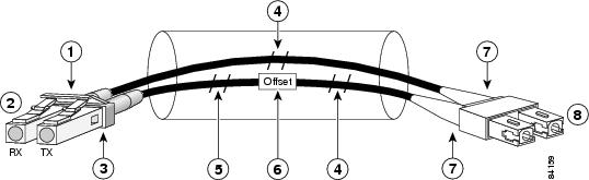
A mode-conditioning patch cord is an optical fiber cable assembly that consists of a pair of optical fibers terminated with connector hardware. Specifically, the mode-conditioning patch cord is composed of a single-mode optical fiber permanently coupled off-center (see Offset in Figure 3-7 and Figure 3-8) to a graded-index multimode optical fiber. Figure 3-7 and Figure 3-8 show a diagram of the mode-conditioning patch cord assembly.
Figure 3-7 Mode Conditioning Patch Cord with SC (GBIC Transceiver) Connector
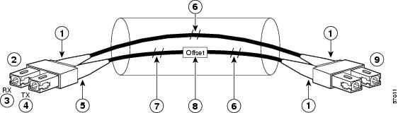
Figure 3-8 Mode Conditioning Patch Cord with LC (SFP Transceiver) Connector
|
|
Gray color identifier |
|
To gigabit Ethernet interface |
|
|
Blue color identifier |
|
Multimode fiber |
|
|
Single-mode fiber |
|
Offset junction |
|
|
Beige color identifier |
|
To cable plant |
The mode-conditioning patch cord assembly is composed of duplex optical fibers, including a single-mode-to-multimode offset launch fiber connected to the transmitter, and a second conventional graded-index multimode optical fiber connected to the receiver. The use of a plug-to-plug patch cord maximizes the power budget of multimode 1000BASE-LX/LH links.
Note ![]() The mode-conditioning patch cord is required to comply with IEEE standards. The IEEE found that link distances could not be met with certain types of fiber-optic cable cores. The solution is to launch light from the laser at a precise offset from the center, which is accomplished by using the mode-conditioning patch cord. At the output end of the patch cord, the GBIC-LX/LH is compliant with the IEEE 802.3z standard for 1000BASE-LX.
The mode-conditioning patch cord is required to comply with IEEE standards. The IEEE found that link distances could not be met with certain types of fiber-optic cable cores. The solution is to launch light from the laser at a precise offset from the center, which is accomplished by using the mode-conditioning patch cord. At the output end of the patch cord, the GBIC-LX/LH is compliant with the IEEE 802.3z standard for 1000BASE-LX.
Connecting Transceivers to a Copper Network
To connect transceivers to a copper network, follow these steps:
Step 1 ![]() Insert the network cable RJ-45 connector into the RJ-45 connector on the transceiver.
Insert the network cable RJ-45 connector into the RJ-45 connector on the transceiver.
Note ![]() When connecting to a 1000BASE-T-compatible switch or repeater, use four-twisted-pair, crossover Category 5 cabling.
When connecting to a 1000BASE-T-compatible switch or repeater, use four-twisted-pair, crossover Category 5 cabling.
Step 2 ![]() Insert the other end of the network cable into an RJ-45 connector on a 1000BASE-T-compatible target device.
Insert the other end of the network cable into an RJ-45 connector on a 1000BASE-T-compatible target device.
Verifying the Installation
This section describes how to verify the installation of a supervisor engine or switching module.
To verify the installation of a Catalyst 6500 series switch running Cisco IOS software, see the Catalyst 6500 Series Switch IOS Software Configuration Guide.
This section contains the following topics:
•![]() Verifying Newly Installed Modules
Verifying Newly Installed Modules
Verifying Newly Installed Modules
Enter the show module or show port [mod_num/port_num] command to verify that the system acknowledges the new modules and has brought them online.
This example shows the output of the show module command:
Console> show module
Mod Slot Ports Module-Type Model Sub Status
--- ---- ----- ------------------------- ------------------- --- --------
1 1 2 1000BaseX Supervisor WS-X6K-SUP1A-2GE yes ok
15 1 1 Multilayer Switch Feature WS-F6K-MSFC no ok
3 3 2 Network Analysis Module WS-X6380-NAM no ok
5 5 48 10/100BaseTX Ethernet WS-X6248-RJ-45 no ok
Mod Module-Name Serial-Num
--- ------------------- -----------
1 SAD03392376
15 SAD03366264
3 JAB0343055Y
5 SAD03181291
Mod MAC-Address(es) Hw Fw Sw
--- -------------------------------------- ------ ---------- -----------------
1 00-30-96-29-9f-84 to 00-30-96-29-9f-85 1.0 5.2(1) 6.1(0.128)ORL
00-30-96-29-9f-86 to 00-30-96-29-9f-87
00-50-3e-8d-64-00 to 00-50-3e-8d-67-ff
15 00-d0-bc-ed-6b-2c to 00-d0-bc-ed-6b-6b 1.2 12.0(7T)XE 12.0(7T)XE1(2.07)
3 00-90-2b-00-a7-ca to 00-90-2b-00-a7-cb 0.201 4B4LZ0XA 1.1(0.20)
5 00-50-f0-ac-30-54 to 00-50-f0-ac-30-83 1.0 4.2(0.24)V 6.1(0.128)ORL
Mod Sub-Type Sub-Model Sub-Serial Sub-Hw
--- ----------------------- ------------------- ----------- ------
1 L3 Switching Engine WS-F6K-PFC SAD03365068 1.0
Console>
This example shows the output of the show port command:
Console> show port 1/1
Port Name Status Vlan Duplex Speed Type
----- ------------------ ---------- ---------- ------ ----- ------------
1/1 connected 1 full 1000 1000BaseSX
Port Security Secure-Src-Addr Last-Src-Addr Shutdown Trap IfIndex
----- -------- ----------------- ----------------- -------- -------- -------
1/1 disabled No disabled 3
Port Broadcast-Limit Broadcast-Drop
-------- --------------- --------------------
1/1 - 0
Port Send FlowControl Receive FlowControl RxPause TxPause
admin oper admin oper
----- -------- -------- -------- -------- ---------- ----------
1/1 desired on off off 0 0
Port Status Channel Admin Ch Neighbor Neighbor
Mode Group Id Device Port
----- ---------- --------- ----- ----- ----------------------------------- -----
1/1 connected auto 123 0
Port Align-Err FCS-Err Xmit-Err Rcv-Err UnderSize
----- ---------- ---------- ---------- ---------- ---------
1/1 0 0 0 0 0
Port Single-Col Multi-Coll Late-Coll Excess-Col Carri-Sen Runts Giants
----- ---------- ---------- ---------- ---------- --------- --------- ---------
1/1 0 0 0 0 23 0 0
Last-Time-Cleared
--------------------------
Fri March 2 2003, 20:41:52
Console>
Checking Connectivity
To check connectivity on any switching module port, perform these tasks:
|
|
|
|---|---|
Ping a host. |
ping host |
If the host is unresponsive, check the IP address of the switch and default IP route, if appropriate. |
show interface |
For example, to ping a host named server1, enter this command:
Console> ping server1
server1 is alive
Console>
What To Do After Installing Modules and Verifying Connectivity
After you verify the switching module installation and check connectivity, you must configure the module. For complete information on configuring the modules, see the Catalyst 6500 Series Switch Software Configuration Guide or the Catalyst 6500 Series Switch Cisco IOS Software Configuration Guide. For information on all Catalyst 6500 series switch commands, see the Catalyst 6500 Series Switch Command Reference or the Catalyst 6500 Series Switch Cisco IOS Command Reference publications.
 Feedback