Table of Contents
Cisco 10-Gigabit Ethernet X2 Transceiver Modules Installation Note
Overview
Safety
Statement 1071—Warning Definition
Required Tools
Installing the 10-Gigabit Ethernet X2 Transceiver Module
Removing the 10-Gigabit Ethernet X2 Transceiver Module
Translated Safety Warnings
Statement 70—Invisible Laser Radiation Warning
Statement 1008—Class 1 Laser Product
Statement 1040—Product Disposal
Statement 1057—Hazardous Radiation Exposure
Related Documentation
Obtaining Documentation and Submitting a Service Request
Cisco 10-Gigabit Ethernet X2 Transceiver Modules Installation Note
Revised: September 23, 2011
Product Numbers:
This installation note provides the installation instructions for the 10-Gigabit Ethernet X2 transceiver modules listed above and contains these sections:
Overview
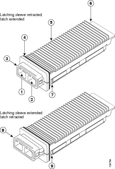
The 10-Gigabit Ethernet X2 transceiver module is a hot-swappable I/O device that plugs into 10-Gigabit Ethernet ports. Figure 1 shows an X2 transceiver module with the major features identified. The X2 transceiver module connects the electrical circuitry of the system with the optical or copper network.
Figure 1 10-Gigabit Ethernet X2 Transceiver Module (Optical Version Shown)
|
|
Transmit optical bore |
|
Module connector |
|
|
Receive optical bore |
|
Latch (extended) |
|
|
Latching sleeve (retracted) |
|
Latching sleeve (extended) |
|
|
EMI gasket flange |
|
Latch (retracted) |
|
|
Transceiver heat sink |
|
|
Note The 10-Gigabit Ethernet X2 transceiver module has either a spring-loaded EMI gasket flange or a non-spring-loaded EMI gasket flange. Both transceiver module types are functionally identical.
The X2 transceiver module product numbers and brief descriptions are provided in Table 1 and Table 2 .
Table 1 10-Gigabit Ethernet X2 Transceiver Modules
|
|
|
X2-10GB-SR |
Cisco 10GBASE-SR X2 transceiver module for MMF, dual SC connector |
X2-10GB-LR |
Cisco 10GBASE-LR X2 transceiver module for SMF, dual SC connector |
X2-10GB-ER |
Cisco 10GBASE-ER X2 transceiver module for SMF, dual SC connector |
X2-10GB-ZR |
Cisco 10GBASE-ZR X2 transceiver module for SMF, dual SC connector |
X2-10GB-CX4 |
Cisco 10GBASE-CX4 X2 transceiver module for CX4 cable, InfiniBand 4x connector |
X2-10GB-LX4 |
Cisco 10GBASE-LX4 X2 transceiver module for MMF, dual SC connector |
X2-10GB-LRM |
Cisco 10GBASE-LRM X2 transceiver module for MMF, dual SC connector |
X2-10GB-T |
Cisco 10GBASE-T X2 transceiver module for CAT6A or CAT7 copper cable, RJ-45 connector |
Table 2 10-Gigabit Ethernet DWDM X2 Transceiver Modules
|
|
|
|
DWDM-X2-60.61= |
10GBASE-DWDM 1560.61 nm X2 (100-GHz ITU grid) |
21 |
DWDM-X2-59.79= |
10GBASE-DWDM 1559.79 nm X2 (100-GHz ITU grid) |
22 |
DWDM-X2-58.98= |
10GBASE-DWDM 1558.98 nm X2 (100-GHz ITU grid) |
23 |
DWDM-X2-58.17= |
10GBASE-DWDM 1558.17 nm X2 (100-GHz ITU grid) |
24 |
DWDM-X2-56.55= |
10GBASE-DWDM 1556.55 nm X2 (100-GHz ITU grid) |
26 |
DWDM-X2-55.75= |
10GBASE-DWDM 1555.75 nm X2 (100-GHz ITU grid) |
27 |
DWDM-X2-54.94= |
10GBASE-DWDM 1554.94 nm X2 (100-GHz ITU grid) |
28 |
DWDM-X2-54.13= |
10GBASE-DWDM 1554.13 nm X2 (100-GHz ITU grid) |
29 |
DWDM-X2-52.52= |
10GBASE-DWDM 1552.52 nm X2 (100-GHz ITU grid) |
31 |
DWDM-X2-51.72= |
10GBASE-DWDM 1551.72 nm X2 (100-GHz ITU grid) |
32 |
DWDM-X2-50.92= |
10GBASE-DWDM 1550.92 nm X2 (100-GHz ITU grid) |
33 |
DWDM-X2-50.12= |
10GBASE-DWDM 1550.12 nm X2 (100-GHz ITU grid) |
34 |
DWDM-X2-48.51= |
10GBASE-DWDM 1548.51 nm X2 (100-GHz ITU grid) |
36 |
DWDM-X2-47.72= |
10GBASE-DWDM 1547.72 nm X2 (100-GHz ITU grid) |
37 |
DWDM-X2-46.92= |
10GBASE-DWDM 1546.92 nm X2 (100-GHz ITU grid) |
38 |
DWDM-X2-46.12= |
10GBASE-DWDM 1546.12 nm X2 (100-GHz ITU grid) |
39 |
DWDM-X2-44.53= |
10GBASE-DWDM 1544.53 nm X2 (100-GHz ITU grid) |
41 |
DWDM-X2-43.73= |
10GBASE-DWDM 1543.73 nm X2 (100-GHz ITU grid) |
42 |
DWDM-X2-42.94= |
10GBASE-DWDM 1542.94 nm X2 (100-GHz ITU grid) |
43 |
DWDM-X2-42.14= |
10GBASE-DWDM 1542.14 nm X2 (100-GHz ITU grid) |
44 |
DWDM-X2-40.56= |
10GBASE-DWDM 1540.56 nm X2 (100-GHz ITU grid) |
46 |
DWDM-X2-39.77= |
10GBASE-DWDM 1539.77 nm X2 (100-GHz ITU grid) |
47 |
DWDM-X2-38.98= |
10GBASE-DWDM 1538.98 nm X2 (100-GHz ITU grid) |
48 |
DWDM-X2-38.19= |
10GBASE-DWDM 1538.19 nm X2 (100-GHz ITU grid) |
49 |
DWDM-X2-36.61= |
10GBASE-DWDM 1536.61 nm X2 (100-GHz ITU grid) |
51 |
DWDM-X2-35.82= |
10GBASE-DWDM 1535.82 nm X2 (100-GHz ITU grid) |
52 |
DWDM-X2-35.04= |
10GBASE-DWDM 1535.04 nm X2 (100-GHz ITU grid) |
53 |
DWDM-X2-34.25= |
10GBASE-DWDM 1534.25 nm X2 (100-GHz ITU grid) |
54 |
DWDM-X2-32.68= |
10GBASE-DWDM 1532.68 nm X2 (100-GHz ITU grid) |
56 |
DWDM-X2-31.90= |
10GBASE-DWDM 1531.90 nm X2 (100-GHz ITU grid) |
57 |
DWDM-X2-31.12= |
10GBASE-DWDM 1531.12 nm X2 (100-GHz ITU grid) |
58 |
DWDM-X2-30.33= |
10GBASE-DWDM 1530.33 nm X2 (100-GHz ITU grid) |
59 |

Note The dual SC connectors on the X2 transceiver modules support network interface cables with either Physical Contact (PC) or Ultra-Physical Contact (UPC) polished face types. The dual SC connectors on the X2 transceiver modules do not support network interface cables with an Angle Polished Connector (APC) polished face type.
Table 3 lists the port cabling specifications for the 10-Gigabit Ethernet X2 transceiver modules. Table 4 lists the X2 transceiver modules optical transmit and receive specifications.
Table 3 X2 Transceiver Port Cabling Specifications
|
|
|
|
|
|
|
X2-10GB-SR |
850 |
MMF |
62.5
62.5
50.0
50.0
50.0 |
160
200
400
500
2000 |
26 m (85.3 feet)
33 m (108.3 feet)
66 m (216.5 feet)
82 m (269 feet)
300 m (984.3 feet) |
X2-10GB-LR |
1310 |
SMF |
G.652 fiber |
— |
10 km (6.21 miles) |
X2-10GB-ER |
1550 |
SMF |
G.652 fiber |
— |
40 km (24.84 miles) |
X2-10GB-ZR |
1550 |
SMF |
G.652 fiber |
— |
80 km (49.72 miles) |
X2-10GB-LX4 |
1310 |
MMF |
62.5
50.0
50.0 |
500
400
500 |
300 m (984.3 feet)
240 m (787.4 feet)
300 m (984.3 feet) |
X2-10GB-CX4 |
— |
InfiniBand (copper) |
— |
— |
15 m (49.2 feet) |
X2-10GB-LRM |
1310 |
MMF |
62.5
50.0
50.0 |
500
400
500 |
220 m (722 feet)
100 m (328 feet)
220 m (722 feet) |
DWDM-X2-xx.xx |
See Table 5 |
SMF |
G.652 fiber |
— |
80 km (49.72 miles) 4 |
X2-10GB-T |
— |
CAT6A/
CAT7 (copper) |
— |
— |
100 m (328 feet) |
Table 4 X2 Transceiver Modules Optical Transmit and Receive Specifications
|
|
|
|
|
Transmit and Receive Wavelength (nm)
|
X2-10GB-SR |
10GBASE-SR, 850-nm MMF |
–1.0 (Max)
–7.3 (Min) |
–1.0 (Max)
–9.9 (Min) |
840 to 860 |
X2-10GB-LR |
10GBASE-LR, 1310-nm SMF |
0.5 (Max)
–8.2 (Min) |
0.5 (Max)
–14.4 (Min) |
1260 to 1355 |
X2-10GB-ER |
10GBASE-ER, 1550-nm SMF |
4.0 (Max)
–4.7 (Min) |
–1.0 (Max)
–15.8 (Min) |
1530 to 1565 |
X2-10GB-ZR |
10GBASE-ZR, 1550-nm SMF |
4.0 (Max) 0 (Min) |
–7.0 (Max) –24.0 (Min) |
1530 to1565 |
X2-10GB-LX4 |
10GBASE-LX4 WWDM 1300-nm MMF |
– 0.5 per lane (Max) –6.75 per lane in OMA (Min) |
–0.5 per lane (Max) –14.25 per lane in OMA (Min) |
Four lanes; overall range: 1269 to 1356 |
X2-10GB-LRM |
10GBASE-LR, 1310-nm MMF |
0.5 (Max) –6.5 (Min) |
0.5 (Max) –8.4 (Min average) and
–6.4 (Min in OMA) |
1260 to 1355 |
Table 5 lists the optical specifications of the DWDM X2 transceiver modules.
Table 5 DWDM X2 Transceiver Modules Optical Transmit and Receive Specifications
|
|
|
|
|
|
|
|
| Transmitter |
Spectral Width |
— |
— |
— |
0.2 |
m |
Full width, –20 dB from maximum, with resolution bandwidth (RBW) = 0.01 nm. |
Transmitter Center Wavelength |
— |
x–100 |
x |
x+100 |
pm |
Refer to Table 2 for center wavelengths. |
Side-Mode Suppression Ratio |
SMSR |
30 |
— |
— |
dB |
— |
Transmitter Extinction Ratio |
OMI |
9 |
— |
— |
dB |
— |
Transmitter Optical Output Power |
P-out |
–1.0 |
— |
3.0 |
dBm |
Average power coupled into single-mode fiber. |
| Receiver |
Receiver Optical Input Wavelength |
— |
1530 |
— |
1565 |
nm |
— |
Receiver Damage Threshold |
— |
— |
— |
–1 |
dBm |
— |
Dispersion Tolerance |
— |
–500 |
|
1600 |
ps/nm |
— |
| Power-Limited Performance (measured at optical signal-to-noise ratio [OSNR] of 30 dB at 0.1-nm RBW) |
Optical Input Power |
Pin |
–23.0 |
|
–7.0 |
dBm |
|
Dispersion Power Penalty |
|
|
|
3 |
dB |
1 |
| Noise-Limited Performance (measured at OSNR of 24 dB at 0.1-nm RBW) |
Optical Input Power |
Pin |
–17.0 |
|
–7.0 |
dBm |
1 |
Dispersion OSNR Penalty |
|
|
|
3 |
dB |
1 |
Safety
Safety warnings appear throughout this publication to highlight circumstances that might harm you or the equipment. A warning symbol precedes each warning statement.
Statement 1071—Warning Definition
Warning |
IMPORTANT SAFETY INSTRUCTIONS This warning symbol means danger. You are in a situation that could cause bodily injury. Before you work on any equipment, be aware of the hazards involved with electrical circuitry and be familiar with standard practices for preventing accidents. Use the statement number provided at the end of each warning to locate its translation in the translated safety warnings that accompanied this device. SAVE THESE INSTRUCTIONS |
| Waarschuwing |
BELANGRIJKE VEILIGHEIDSINSTRUCTIES Dit waarschuwingssymbool betekent gevaar. U verkeert in een situatie die lichamelijk letsel kan veroorzaken. Voordat u aan enige apparatuur gaat werken, dient u zich bewust te zijn van de bij elektrische schakelingen betrokken risico's en dient u op de hoogte te zijn van de standaard praktijken om ongelukken te voorkomen. Gebruik het nummer van de verklaring onderaan de waarschuwing als u een vertaling van de waarschuwing die bij het apparaat wordt geleverd, wilt raadplegen. BEWAAR DEZE INSTRUCTIES |
| Varoitus |
TÄRKEITÄ TURVALLISUUSOHJEITA Tämä varoitusmerkki merkitsee vaaraa. Tilanne voi aiheuttaa ruumiillisia vammoja. Ennen kuin käsittelet laitteistoa, huomioi sähköpiirien käsittelemiseen liittyvät riskit ja tutustu onnettomuuksien yleisiin ehkäisytapoihin. Turvallisuusvaroitusten käännökset löytyvät laitteen mukana toimitettujen käännettyjen turvallisuusvaroitusten joukosta varoitusten lopussa näkyvien lausuntonumeroiden avulla. SÄILYTÄ NÄMÄ OHJEET |
| Attention |
IMPORTANTES INFORMATIONS DE SÉCURITÉ Ce symbole d'avertissement indique un danger. Vous vous trouvez dans une situation pouvant entraîner des blessures ou des dommages corporels. Avant de travailler sur un équipement, soyez conscient des dangers liés aux circuits électriques et familiarisez-vous avec les procédures couramment utilisées pour éviter les accidents. Pour prendre connaissance des traductions des avertissements figurant dans les consignes de sécurité traduites qui accompagnent cet appareil, référez-vous au numéro de l'instruction situé à la fin de chaque avertissement. CONSERVEZ CES INFORMATIONS |
| Warnung |
WICHTIGE SICHERHEITSHINWEISE Dieses Warnsymbol bedeutet Gefahr. Sie befinden sich in einer Situation, die zu Verletzungen führen kann. Machen Sie sich vor der Arbeit mit Geräten mit den Gefahren elektrischer Schaltungen und den üblichen Verfahren zur Vorbeugung vor Unfällen vertraut. Suchen Sie mit der am Ende jeder Warnung angegebenen Anweisungsnummer nach der jeweiligen Übersetzung in den übersetzten Sicherheitshinweisen, die zusammen mit diesem Gerät ausgeliefert wurden. BEWAHREN SIE DIESE HINWEISE GUT AUF. |
| Avvertenza |
IMPORTANTI ISTRUZIONI SULLA SICUREZZA Questo simbolo di avvertenza indica un pericolo. La situazione potrebbe causare infortuni alle persone. Prima di intervenire su qualsiasi apparecchiatura, occorre essere al corrente dei pericoli relativi ai circuiti elettrici e conoscere le procedure standard per la prevenzione di incidenti. Utilizzare il numero di istruzione presente alla fine di ciascuna avvertenza per individuare le traduzioni delle avvertenze riportate in questo documento. CONSERVARE QUESTE ISTRUZIONI |
| Advarsel |
VIKTIGE SIKKERHETSINSTRUKSJONER Dette advarselssymbolet betyr fare. Du er i en situasjon som kan føre til skade på person. Før du begynner å arbeide med noe av utstyret, må du være oppmerksom på farene forbundet med elektriske kretser, og kjenne til standardprosedyrer for å forhindre ulykker. Bruk nummeret i slutten av hver advarsel for å finne oversettelsen i de oversatte sikkerhetsadvarslene som fulgte med denne enheten. TA VARE PÅ DISSE INSTRUKSJONENE |
| Aviso |
INSTRUÇÕES IMPORTANTES DE SEGURANÇA Este símbolo de aviso significa perigo. Você está em uma situação que poderá ser causadora de lesões corporais. Antes de iniciar a utilização de qualquer equipamento, tenha conhecimento dos perigos envolvidos no manuseio de circuitos elétricos e familiarize-se com as práticas habituais de prevenção de acidentes. Utilize o número da instrução fornecido ao final de cada aviso para localizar sua tradução nos avisos de segurança traduzidos que acompanham este dispositivo. GUARDE ESTAS INSTRUÇÕES |
| ¡Advertencia! |
INSTRUCCIONES IMPORTANTES DE SEGURIDAD Este símbolo de aviso indica peligro. Existe riesgo para su integridad física. Antes de manipular cualquier equipo, considere los riesgos de la corriente eléctrica y familiarícese con los procedimientos estándar de prevención de accidentes. Al final de cada advertencia encontrará el número que le ayudará a encontrar el texto traducido en el apartado de traducciones que acompaña a este dispositivo. GUARDE ESTAS INSTRUCCIONES |
| Varning! |
VIKTIGA SÄKERHETSANVISNINGAR Denna varningssignal signalerar fara. Du befinner dig i en situation som kan leda till personskada. Innan du utför arbete på någon utrustning måste du vara medveten om farorna med elkretsar och känna till vanliga förfaranden för att förebygga olyckor. Använd det nummer som finns i slutet av varje varning för att hitta dess översättning i de översatta säkerhetsvarningar som medföljer denna anordning. SPARA DESSA ANVISNINGAR |
|
|
|
|
|
|
|
|
|
|
|
|
|
|
|
| Aviso |
INSTRUÇÕES IMPORTANTES DE SEGURANÇA Este símbolo de aviso significa perigo. Você se encontra em uma situação em que há risco de lesões corporais. Antes de trabalhar com qualquer equipamento, esteja ciente dos riscos que envolvem os circuitos elétricos e familiarize-se com as práticas padrão de prevenção de acidentes. Use o número da declaração fornecido ao final de cada aviso para localizar sua tradução nos avisos de segurança traduzidos que acompanham o dispositivo. GUARDE ESTAS INSTRUÇÕES |
| Advarsel |
VIGTIGE SIKKERHEDSANVISNINGER Dette advarselssymbol betyder fare. Du befinder dig i en situation med risiko for legemesbeskadigelse. Før du begynder arbejde på udstyr, skal du være opmærksom på de involverede risici, der er ved elektriske kredsløb, og du skal sætte dig ind i standardprocedurer til undgåelse af ulykker. Brug erklæringsnummeret efter hver advarsel for at finde oversættelsen i de oversatte advarsler, der fulgte med denne enhed. GEM DISSE ANVISNINGER |
|
|
|
|
|
|
|
|
|
|
|
|
|
|
|
|
|
|
|
|
|
|
|
|

Warning Class 1 laser product. Statement 1008
Warning Because invisible laser radiation may be emitted from the aperture of the port when no cable is connected, avoid exposure to laser radiation and do not stare into open apertures. Statement 70
Warning Ultimate disposal of this product should be handled according to all national laws and regulations. Statement 1040
Warning Use of controls, adjustments, or performing procedures other than those specified may result in hazardous radiation exposure. Statement 1057
Required Tools
You will need these tools to install the 10-Gigabit Ethernet X2 transceiver modules:
- Small flat-blade screwdriver for removing the X2 transceiver socket covers.
- Wrist strap or other personal grounding device to prevent ESD occurrences.
- Antistatic mat or antistatic foam to set the transceiver on.
- Fiber-optic end-face cleaning tools and inspection equipment. For complete information on inspecting and cleaning fiber-optic connections, refer to the Inspection and Cleaning Procedures for Fiber-Optic Connections document at this URL:
http://www.cisco.com/en/US/tech/tk482/tk876/technologies_white_paper09186a0080254eba.shtml
Installing the 10-Gigabit Ethernet X2 Transceiver Module
Note This installation procedure applies to both the spring-loaded and non-spring-loaded X2 transceiver modules.
Caution The X2 transceiver is a static-sensitive device. Always use an ESD wrist strap or similar individual grounding device when handling X2 transceivers or coming into contact with system modules.
To install an X2 transceiver module, follow these steps:
Step 1 Using a small flat-blade screwdriver, carefully pry the X2 transceiver port cover off of the system module faceplate. Use the two arrows on the port cover as guides for inserting the screwdriver blade. Save the port cover for future use.
Step 2 Remove the new X2 transceiver module from its protective packaging.
Step 3 Check the label on the X2 transceiver module body to verify that you have the correct model for your network.
Step 4 Remove the dust plug from X2 transceiver module optical port and set it aside.
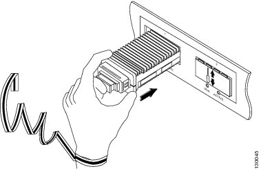
Step 5 Slide the X2 transceiver into the transceiver socket on the system module front panel until the X2 transceiver EMI gasket flange makes contact with the system module faceplate. (See Figure 2.)
Note 10-Gigabit Ethernet X2 transceiver modules are keyed to prevent incorrect insertion.
Figure 2 Installing the 10-Gigabit Ethernet X2 Transceiver Module
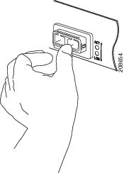
Step 6 Press firmly on the front of the X2 transceiver module with your thumb to fully seat the transceiver in the transceiver socket. (See Figure 3.)
Figure 3 Latching the X2 Transceiver Module
Step 7 Verify that the X2 transceiver is properly seated and latched in the socket, by grasping the left and right sides (or the top and bottom) of the transceiver’s EMI gasket flange with your thumb and forefinger and gently pulling on the transceiver. Do not pull on the latching sleeve as you will release the transceiver.
If the transceiver does not pull free, it is properly seated and latched.
If the transceiver does pull free, slide the X2 transceiver back into the socket and apply more pressure with your thumb on the front of the transceiver. Repeat the process until the X2 transceiver is securely latched in the socket.
Step 8 Reinstall the dust plug into the transceiver’s optical bore until you are ready to attach the network interface cable.
Step 9 If you are cabling an optical X2 transceiver module, follow these sub-steps. If you are cabling a CX4 X2 transceiver module, go to step 10.
a. Remove the dust plugs from the optical network interface cable SC connectors. Save the dust plugs for future use.
b. Inspect and clean the SC connector’s fiber-optic end faces.
For complete information on inspecting and cleaning fiber-optic connections, refer to the Inspection and Cleaning Procedures for Fiber-Optic Connections document at this URL:
http://www.cisco.com/en/US/tech/tk482/tk876/technologies_white_paper09186a0080254eba.shtml
c. Remove the dust plugs from the X2 transceiver module optical bores.
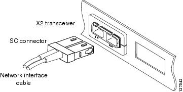
d. Immediately attach the network interface cable SC connectors to the X2 transceiver module. (See Figure 4.)
Figure 4 Cabling an Optical 10-Gigabit Ethernet X2 Transceiver Module
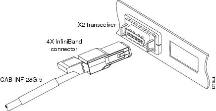
Step 10 Plug the InfiniBand cable connector into the CX4 X2 transceiver module connector. (See Figure 5.) Make sure that the InfiniBand cable connector is aligned with the X2 transceiver module.
Figure 5 Cabling a CX4 (Copper) 10-Gigabit Ethernet X2 Transceiver Module
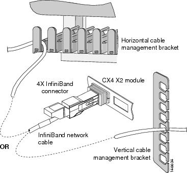
Step 11 Carefully route the InfiniBand network cable through the cable management brackets on your system. Figure 6 shows how the InfiniBand cable should be routed through either a horizontal cable management bracket or a vertical cable management bracket.
Note Make sure that you route the InfiniBand cable through cable management brackets to provide adequate strain relief and cable support when cabling CX4 X2 transceiver modules. The InfiniBand cable is heavy. Without proper support, the InfiniBand cable can cause the cable connector to sag or skew. Misalignment between the cable connector and the transceiver module connector can cause intermittent connections between the cable connector pins and the CX4 X2 transceiver module pins.
Figure 6 InfiniBand Cable Support
Removing the 10-Gigabit Ethernet X2 Transceiver Module
Warning Class 1 laser product. Statement 1008
Warning Because invisible laser radiation may be emitted from the aperture of the port when no cable is connected, avoid exposure to laser radiation and do not stare into open apertures. Statement 70
Warning Ultimate disposal of this product should be handled according to all national laws and regulations. Statement 1040
Warning Use of controls, adjustments, or performing procedures other than those specified may result in hazardous radiation exposure. Statement 1057
Note This removal procedure applies to both the spring-loaded and non-spring-loaded X2 transceiver modules.
Caution The X2 transceiver module is a static-sensitive device. Always use an ESD wrist strap or similar individual grounding device when handling X2 transceiver modules or coming into contact with modules.
To remove an X2 transceiver, follow these steps:
Step 1 Disconnect the network interface cable from the X2 transceiver module connectors. If this is an optical X2 transceiver module, immediately reinstall dust plugs in the X2 transceiver module optical bores and in the fiber-optic cable SC connectors.
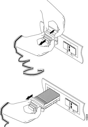
Step 2 Place your thumb and forefinger around the X2 transceiver module EMI gasket flange and gently press the EMI gasket flange against the system module front panel. (See Figure 7, top view.) At the same time, with the thumb and forefinger of your other hand, grip the sides of the X2 transceiver module latching sleeve, and pull the latching sleeve out to release the X2 transceiver module from the socket connector. Release the latching sleeve when you feel the X2 transceiver module unlatch.
Step 3 Slide the X2 transceiver module out of the socket. (See Figure 7, bottom view.) Immediately place the X2 transceiver module in an antistatic bag.
Step 4 If you are not installing an X2 transceiver module in the empty socket, place a socket cover over the empty socket opening and press on the cover until it snaps into place.
Figure 7 Removing the 10-Gigabit Ethernet X2 Transceiver Module
Translated Safety Warnings
This section repeats in multiple languages the basic warnings that appear in this document.
Statement 70—Invisible Laser Radiation Warning
Warning
|
Because invisible laser radiation may be emitted from the aperture of the port when no cable is connected, avoid exposure to laser radiation and do not stare into open apertures. |
| Waarschuwing |
Omdat er onzichtbare laserstraling uit de opening van de poort geëmitteerd kan worden wanneer er geen kabel aangesloten is, dient men om blootstelling aan laserstraling te vermijden niet in de open openingen te kijken. |
| Varoitus |
Kun porttiin ei ole kytketty kaapelia, portin aukosta voi vuotaa näkymätöntä lasersäteilyä. Älä katso avoimiin aukkoihin, jotta et altistu säteilylle. |
| Attention |
Etant donné qu’un rayonnement laser invisible peut être émis par l’ouverture du port quand aucun câble n’est connecté, ne pas regarder dans les ouvertures béantes afin d’éviter tout risque d’exposition au rayonnement laser. |
| Warnung |
Aus der Öffnung des Ports kann unsichtbare Laserstrahlung austreten, wenn kein Kabel angeschlossen ist. Kontakt mit Laserstrahlung vermeiden und nicht in offene Öffnungen blicken. |
| Avvertenza |
Poiché quando nessun cavo è collegato alla porta, da quest’ultima potrebbe essere emessa radiazione laser invisibile, evitare l’esposizione a tale radiazione e non fissare con gli occhi porte a cui non siano collegati cavi. |
| Advarsel |
Usynlige laserstråler kan sendes ut fra åpningen på utgangen når ingen kabel er tilkoblet. Unngå utsettelse for laserstråling og se ikke inn i åpninger som ikke er tildekket. |
| Aviso |
Evite uma exposição à radiação laser e não olhe através de aberturas expostas, porque poderá ocorrer emissão de radiação laser invisível a partir da abertura da porta, quando não estiver qualquer cabo conectado. |
| ¡Advertencia! |
Cuando no esté conectado ningún cable, pueden emitirse radiaciones láser invisibles por el orificio del puerto. Evitar la exposición a radiaciones láser y no mirar fijamente los orificios abiertos. |
| Varning! |
Osynliga laserstrålar kan sändas ut från öppningen i porten när ingen kabel är ansluten. Undvik exponering för laserstrålning och titta inte in i ej täckta öppningar.
|
Statement 1008—Class 1 Laser Product
Warning |
Class 1 laser product. |
| Waarschuwing |
Klasse-1 laser produkt. |
| Varoitus |
Luokan 1 lasertuote. |
| Attention |
Produit laser de classe 1. |
| Warnung |
Laserprodukt der Klasse 1. |
| Avvertenza |
Prodotto laser di Classe 1. |
| Advarsel |
Laserprodukt av klasse 1. |
| Aviso |
Produto laser de classe 1. |
| ¡Advertencia! |
Producto láser Clase I. |
| Varning! |
Laserprodukt av klass 1. |
|
|
|
|
|
|
|
|
|
|
|
|
|
|
|
| Aviso |
Produto a laser de classe 1. |
| Advarsel |
Klasse 1 laserprodukt. |
|
|
|
|
|
|
|
|
|
|
|
|
|
|
|
|
|
|
|
|
|
|
|
|
Statement 1040—Product Disposal
Warning
|
Ultimate disposal of this product should be handled according to all national laws and regulations. |
| Waarschuwing |
Het uiteindelijke wegruimen van dit product dient te geschieden in overeenstemming met alle nationale wetten en reglementen. |
| Varoitus |
Tämä tuote on hävitettävä kansallisten lakien ja määräysten mukaisesti. |
| Attention |
La mise au rebut ou le recyclage de ce produit sont généralement soumis à des lois et/ou directives de respect de l'environnement. Renseignez-vous auprès de l'organisme compétent. |
| Warnung |
Die Entsorgung dieses Produkts sollte gemäß allen Bestimmungen und Gesetzen des Landes erfolgen. |
| Avvertenza |
Lo smaltimento di questo prodotto deve essere eseguito secondo le leggi e regolazioni locali. |
| Advarsel |
Endelig kassering av dette produktet skal være i henhold til alle relevante nasjonale lover og bestemmelser. |
| Aviso |
Deitar fora este produto em conformidade com todas as leis e regulamentos nacionais. |
| ¡Advertencia! |
Al deshacerse por completo de este producto debe seguir todas las leyes y reglamentos nacionales. |
| Varning! |
Vid deponering hanteras produkten enligt gällande lagar och bestämmelser. |
|
|
|
|
|
|
|
|
|
|
|
|
|
|
|
| Aviso |
O descarte definitivo deste produto deve estar de acordo com todas as leis e regulamentações nacionais. |
| Advarsel |
Endelig bortskaffelse af dette produkt skal ske i henhold til gældende love og regler. |
|
|
|
|
|
|
|
|
|
|
|
|
|
|
|
|
|
|
|
|
|
|
|
|
|
|
|
|
|
|
Statement 1057—Hazardous Radiation Exposure
Warning
|
Use of controls, adjustments, or performing procedures other than those specified may result in hazardous radiation exposure. |
| Waarschuwing |
Het gebruik van regelaars of bijstellingen of het uitvoeren van procedures anders dan opgegeven kan leiden tot blootstelling aan gevaarlijke straling. |
| Varoitus |
Säätimien tai säätöjen käyttö ja toimenpiteiden suorittaminen ohjeista poikkeavalla tavalla voi altistaa vaaralliselle säteilylle. |
| Attention |
L’utilisation de commandes, de réglages ou de procédures autres que ceux spécifiés peut entraîner une exposition dangereuse à des radiations. |
| Warnung |
Die Verwendung von nicht spezifizierten Steuerelementen, Einstellungen oder Verfahrensweisen kann eine gefährliche Strahlenexposition zur Folge haben. |
| Avvertenza |
L’adozione di controlli, regolazioni o procedure diverse da quelle specificate può comportare il pericolo di esposizione a radiazioni. |
| Advarsel |
Bruk av kontroller eller justeringer eller utførelse av prosedyrer som ikke er spesifiserte, kan resultere i farlig strålingseksponering. |
| Aviso |
O uso de controles, ajustes ou desempenho de procedimentos diferentes dos especificados pode resultar em exposição prejudicial de radiação. |
| ¡Advertencia! |
La aplicación de controles, ajustes y procedimientos distintos a los especificados puede comportar una exposición peligrosa a la radiación. |
| Varning! |
Om andra kontroller eller justeringar än de angivna används, eller om andra processer än de angivna genomförs, kan skadlig strålning avges. |
|
|
|
|
|
|
|
|
|
|
|
|
|
|
|
| Aviso |
O uso de controles, ajustes ou procedimentos diferentes daqueles especificados pode resultar em exposição perigosa à radiação. |
| Advarsel |
Brug af kontrolfunktioner, justeringer, eller udførelse af procedurer andre end de, der er angivet, kan resultere i udsættelse for farlig bestråling. |
|
|
|
|
|
|
|
|
|
|
|
|
|
|
|
|
|
|
|
|
|
|
|
|
Related Documentation
For hardware installation and maintenance information on specific Cisco routers and switches, see the installation and configuration guide for your router or switch.
For software configuration information and support, see the Cisco IOS software configuration and command reference publications for the installed Cisco IOS software release or the Catalyst operating system software configuration and command reference publications for the installed Catalyst operating system software release.
A compatibility matrix for 10-Gigabit transceivers is available at the following URL:
http://www.cisco.com/en/US/docs/interfaces_modules/transceiver_modules/compatibility/matrix/OL_6974.html
The compatibility matrix provides a listing of the available X2 transceivers, the hardware platforms they are supported on, and the minimum software version required to operate the X2 transceivers.
Obtaining Documentation and Submitting a Service Request
For information on obtaining documentation, submitting a service request, and gathering additional information, see the monthly What’s New in Cisco Product Documentation , which also lists all new and revised Cisco technical documentation, at:
http://www.cisco.com/en/US/docs/general/whatsnew/whatsnew.html
Subscribe to the What’s New in Cisco Product Documentation as a Really Simple Syndication (RSS) feed and set content to be delivered directly to your desktop using a reader application. The RSS feeds are a free service and Cisco currently supports RSS Version 2.0.
This document is to be used in conjunction with the publications documents that support your specific Cisco device.
Cisco and the Cisco Logo are trademarks of Cisco Systems, Inc. and/or its affiliates in the U.S. and other countries. A listing of Cisco's trademarks can be found at www.cisco.com/go/trademarks . Third party trademarks mentioned are the property of their respective owners. The use of the word partner does not imply a partnership relationship between Cisco and any other company. (1005R)
Copyright © 2004–2011, Cisco Systems, Inc. All rights reserved.


 Feedback