Table Of Contents
Catalyst 4500 E-Series Module Installation Note
Module Overview
Module Support and Restrictions
E-Series 10-Gigabit Ethernet Modules
E-Series 10/100/1000 Ethernet Modules
E-Series 1000BASE Ethernet Modules
Classic 10/100/1000 Ethernet Modules
Classic 1000BASE Ethernet Modules
Classic Fast Ethernet Modules
Classic 10/100 Ethernet Modules
Module LEDs
Transceiver Support
Power over Ethernet Support
Safety
Statement 1071—Warning Definition
Module Installation
Required Tools
Installing the Modules
Removing the Modules
Configuring the Module
Setting Up Power Over Ethernet
Obtaining Documentation and Submitting a Service Request
Catalyst 4500 E-Series Module Installation Note
Revised: November 2012
Product Numbers:
WS-X4712-SFP+E
|
WS-X4606-X2-E
|
WS-X4624-SFP-E
|
WS-X4612-SFP-E
|
WS-X4748-RJ45V+E
|
WS-X4648-RJ45V+E
|
WS-X4648-RJ45V-E
|
WS-X4648-RJ45-E
|
WS-X4548-RJ45V+
|
WS-X4548-GB-RJ45V
|
WS-X4548-GB-RJ45
|
WS-X4306-GB
|
WS-X4418-GB
|
WS-X4448-GB-SFP
|
WS-X4506-GB-T
|
WS-X4248-RJ45V
|
WS-X4148-RJ
|
WS-X4248-FE-SFP
|
WS-X4748-UPOE+E
|
WS-X4748-RJ45-E
|
WS-X4640-CSFP-E
|
|
|
|
This document provides instructions for installing modules in Catalyst 4500 series chassis.
Module Overview
Table 1 provides a brief description of each module, and provides the per slot bandwidth and maximum rated power of the E-series and classic modules.
Table 1 Catalyst 4500 E-Series and Classic Modules
Module
|
Description
|
Per Slot Bandwidth
|
Maximum Rated Power (W)
|
E-Series 10-Gigabit Ethernet Modules
|
WS-X4712-SFP+E
|
12-port, 10-Gigabit Ethernet module
|
48 Gbps
|
90
|
WS-X4606-X2-E
|
6-port, 10-Gigabit Ethernet module. Can also be configured as a 12-port 1000BASE-X module using TwinGig Converter modules and SFP transceivers.
Note TwinGig converters must be used in groups of 3 ports; either ports 1-3 or ports 4-6.
|
24 Gbps
|
50
|
E-Series 10/100/1000 Ethernet Modules
|
WS-X4748-UPOE+E
|
Cisco UPOE 48-port intelligent 60 W PoE1 per port (maximum of 1500 W per module) 10/100/1000 Ethernet module. Module supports 48 ports at 30 W per port simultaneously or 24 ports at 60 W per port simultaneously.
|
48 Gbps
|
80
|
WS-X4748-RJ45V+E
|
48-port, IEEE 802.3at, IEEE 802.3af, and Cisco prestandard, 10/100/1000 Ethernet module
|
24 Gbps
|
75
|
WS-X4748-RJ45-E
|
48-port, 10/100/1000 data only module for the Catalyst 4500 E-series and +E-series chassis.
|
48 Gbps
|
75
|
WS-X4648-RJ45V+E
|
48-port, IEEE 802.3at, IEEE 802.3af, and Cisco prestandard, 10/100/1000 Ethernet module
|
24 Gbps
|
92
|
WS-X4648-RJ45V-E
|
48-port, IEEE 802.3af and Cisco prestandard, 10/100/1000 Ethernet module
|
24 Gbps
|
92
|
WS-X4648-RJ45-E
|
48-port, 10/100/1000 Ethernet module
|
24 Gbps
|
89
|
E-Series 1000BASE Ethernet Modules
|
WS-X4640-CSFP-E
|
40-port SFP or 80-port CSFP 1000BASE-X module (requires either SFP or CSFP transceivers)
|
24 Gbps
|
160
|
WS-X4624-SFP-E
|
24-port, 1000BASE-X Ethernet module. (requires SFP transceivers)
|
24 Gbps
|
45
|
WS-X4612-SFP-E
|
12-port, 1000BASE-X Ethernet module. (requires SFP transceivers)
|
24 Gbps
|
30
|
Classic 10/100/1000 Ethernet Modules
|
WS-X4548-RJ45V+
|
48-port PoE IEEE 802.3at, IEEE 802.3af, and Cisco prestandard 10/100/1000 Ethernet module
|
6 Gbps
|
60
|
WS-X4548-GB-RJ45V
|
48-port PoE IEEE 802.3af, and Cisco prestandard 10/100/1000 Ethernet module
|
6 Gbps
|
60
|
WS-X4524-GB-RJ45V
|
24-port PoE IEEE 802.3af, and Cisco prestandard 10/100/1000 Ethernet module
|
6 Gbps
|
35
|
Classic 1000BASE Ethernet Modules
|
WS-X4306-GB
|
6-port Gigabit Ethernet module (requires GBIC transceivers)
|
6 Gbps
|
35
|
WS-X4418-GB
|
18-port Gigabit Ethernet module (requires GBIC transceivers)
|
6 Gbps
|
80
|
WS-X4448-GB-SFP
|
48-port Gigabit Ethernet module (requires SFP transceivers)
|
6 Gbps
|
65
|
WS-X4506-GB-T
|
6-port 10/100/1000 PoE IEEE 802.3af compliant and Cisco prestandard compliant 1000BASE-X Ethernet module (requires SFP transceivers)
|
6 Gbps
|
30
|
Classic Fast Ethernet Modules
|
WS-X4248-FE-SFP
|
48-port Fast Ethernet module (requires 100BASE-X SFP transceivers)
|
6 Gbps
|
53
|
Classic 10/100 Ethernet Modules
|
WS-X4148-RJ
|
48-port 10/100 Ethernet module
|
6 Gbps
|
65
|
WS-X4248-RJ45V
|
48-port 10/100 PoE IEEE 802.3af compliant Ethernet module
|
6 Gbps
|
60
|
For additional hardware and software information on the Catalyst 4500 series product line including module and chassis data sheets, chassis installation documentation, tech notes, and software release notes, refer to the following URL:
http://www.cisco.com/en/US/products/hw/switches/ps4324/tsd_products_support_series_home.html
Module Support and Restrictions
The Catalyst 4500 series modules can have restrictions on which chassis they can be installed in, the number of modules supported by each chassis, and which supervisor engines support the modules. The tables is this section provide an overview of the restrictions for the modules.
For additional information on module restrictions, refer to the software release notes at the following URL:
http://www.cisco.com/en/US/products/hw/switches/ps4324/tsd_products_support_general_information.html
E-Series 10-Gigabit Ethernet Modules
Table 2 lists the support and restrictions along with the minimum and maximum port density for the E-series 10-Gigabit Ethernet modules.
Table 2 E-Series 10-Gigabit Ethernet Modules Support and Restrictions
Module
|
Support and Restrictions
|
Minimum and Maximum Port Density
|
WS-X4712-SFP+E
|
• Supported only by the Supervisor Engine 7-E.
• Supported only in the Catalyst 4503-E, Catalyst 4506-E, Catalyst 4507R+E, and Catalyst 4510R+E switch chassis.
• Can be installed in any non-supervisor engine slot.
|
• Catalyst 4503—12/24
• Catalyst 4506-E, Catalyst 4507R+E—12/60
• Catalyst 4510R+E—12/96
|
WS-X4606-X2-E
|
• Supported on by the Supervisor Engine 6-E, Supervisor Engine 6L-E, and the Supervisor Engine 7-E
• Supported only in the Catalyst 4503-E, Catalyst 4506-E, Catalyst 4507R+E, and Catalyst 4510R+E switch chassis.
• Can be installed in any non-supervisor engine slot.
|
• Catalyst 4503—6/12 (X2), 12/24 (SFP)
• Catalyst 4506-E, Catalyst 4507R+E—6/30 (X2), 12/60 (SFP)
• Catalyst 4510R+E—6/30 (X2), 12/60 (SFP)
|
E-Series 10/100/1000 Ethernet Modules
Table 3 lists the support and restrictions along with the minimum and maximum port density for the E-series 10/100/1000 Ethernet modules.
Table 3 E-Series 10/100/1000 Ethernet Modules Support and Restrictions
Module
|
Support and Restrictions
|
Minimum and Maximum Port Density
|
WS-X4748-UPOE+E
|
• Supported only by the Supervisor Engine 7-E.
• Supported only in the Catalyst 4503-E, Catalyst 4506-E, Catalyst 4507R-E, Catalyst 4507R+E, Catalyst 4510R-E, and Catalyst 4510R+E switch chassis.
• Can be installed in any non-supervisor engine slot.
|
• Catalyst 4503—48/96
• Catalyst 4506-E, Catalyst 4507R+E—48/240
• Catalyst 4510R+E—48/384
|
WS-X4748-RJ45V+E
|
• Supported only by the Supervisor Engine 7-E.
• Supported only in the Catalyst 4503-E, Catalyst 4506-E, Catalyst 4507R-E, Catalyst 4507R+E, Catalyst 4510R-E, and Catalyst 4510R+E switch chassis.
• Can be installed in any non-supervisor engine slot.
• Catalyst 4510R-E and Catalyst 4510R+E switches equipped with the Supervisor Engine 6-E do not support E-series modules in Slots 8-10.
|
• Catalyst 4503—48/96
• Catalyst 4506-E, Catalyst 4507R+E—48/240
• Catalyst 4510R+E—48/384
|
WS-X4748-RJ45V-E
|
• Supported only by the Supervisor Engine 7-E.
• Supported only in the Catalyst 4503-E, Catalyst 4506-E, Catalyst 4507R-E, Catalyst 4507R+E, Catalyst 4510R-E, and Catalyst 4510R+E switch chassis.
• Can be installed in any non-supervisor engine slot.
• Catalyst 4510R-E and Catalyst 4510R+E switches equipped with the Supervisor Engine 6-E do not support E-series modules in Slots 8-10.
|
• Catalyst 4503—48/96
• Catalyst 4506-E, Catalyst 4507R+E—48/240
• Catalyst 4510R+E—48/384
|
WS-X4648-RJ45V+E
|
• Supported on by the Supervisor Engine 6-E, Supervisor Engine 6L-E, and the Supervisor Engine 7-E
• Supported only in the Catalyst 4503-E, Catalyst 4506-E, Catalyst 4507R+E, and Catalyst 4510R+E switch chassis.
• Can be installed in any non-supervisor engine slot.
|
• Catalyst 4503—48/96
• Catalyst 4506-E, Catalyst 4507R+E—48/240
• Catalyst 4510R+E—48/384
Note You need a Supervisor Engine 7-E to support more than 240 ports on the Catalyst 4510R-E and Catalyst 4510R+E switch chassis
|
WS-X4648-RJ45V-E
|
• Supported on by the Supervisor Engine 6-E, Supervisor Engine 6L-E, and the Supervisor Engine 7-E
• Supported only in the Catalyst 4503-E, Catalyst 4506-E, Catalyst 4507R+E, and Catalyst 4510R+E switch chassis.
• Can be installed in any non-supervisor engine slot.
|
• Catalyst 4503—48/96
• Catalyst 4506-E, Catalyst 4507R+E—48/240
• Catalyst 4510R+E—48/384
• You need a Supervisor Engine 7-E to support more than 240 ports on the Catalyst 4510R-E and Catalyst 4510R+E switch chassis
|
WS-X4648-RJ45-E
|
• Supported on by the Supervisor Engine 6-E, Supervisor Engine 6L-E, and the Supervisor Engine 7-E
• Supported only in the Catalyst 4503-E, Catalyst 4506-E, Catalyst 4507R+E, and Catalyst 4510R+E switch chassis.
• Can be installed in any non-supervisor engine slot.
|
• Catalyst 4503—48/96
• Catalyst 4506-E, Catalyst 4507R+E—48/240
• Catalyst 4510R+E—48/384
• You need a Supervisor Engine 7-E to support more than 240 ports on the Catalyst 4510R-E and Catalyst 4510R+E switch chassis
|
E-Series 1000BASE Ethernet Modules
Table 4 lists the support and restrictions along with the minimum and maximum port density for the E-series 1000BASE Ethernet modules.
Table 4 E-Series 1000BASE Ethernet Modules Support and Restrictions
Module
|
Support and Restrictions
|
Minimum and Maximum Port Density
|
WS-X4624-SFP-E
|
• Supported only by the Supervisor Engine 7-E.
• Supported only in the Catalyst 4503-E, Catalyst 4506-E, Catalyst 4507R+E, and Catalyst 4510R+E switch chassis.
• Can be installed in any non-supervisor engine slot.
|
• Catalyst 4503-E—24/48
• Catalyst 4506-E, Catalyst 4507R+E—24/120
• Catalyst 4510R+E—24/168
|
WS-X4612-SFP-E
|
• Supported on by the Supervisor Engine 6-E, Supervisor Engine 6L-E, and the Supervisor Engine 7-E
• Supported only in the Catalyst 4503-E, Catalyst 4506-E, Catalyst 4507R+E, and Catalyst 4510R+E switch chassis.
• Can be installed in any non-supervisor engine slot.
|
• Catalyst 4503—12/28
• Catalyst 4506-E, Catalyst 4507R+E—12/64
• Catalyst 4510R+E—12/100
|
WS-X4640-CSFP-E
|
• Supported on by the Supervisor Engine 6-E, Supervisor Engine 6L-E, and the Supervisor Engine 7-E
• Supported only in the Catalyst 4503-E, Catalyst 4506-E, Catalyst 4507R+E switch chassis.
• Can be installed in any non-supervisor engine slot.
|
• Catalyst 4503—40/160
• Catalyst 4506-E, Catalyst 4507R+E—40/120
|
Classic 10/100/1000 Ethernet Modules
Table 5 lists the support and restrictions along with the minimum and maximum port density for the classic 10/100/1000 Ethernet modules.
Table 5 Classic 10/100/1000 Ethernet Modules Support and Restrictions
Module
|
Support and Restrictions
|
Minimum and Maximum Port Density
|
WS-X4548-RJ45V+
|
• Supported by the Supervisor Engine V-10GE, Supervisor Engine 6-E, Supervisor Engine 6L-E, Supervisor Engine 7-E.
• Supported in the Catalyst 4500 and Catalyst 4500 E-Series switch chassis.
• Can be installed in any non-supervisor engine slot.
|
• Catalyst 4503-E—48/96
• Catalyst 4506-E, Catalyst 4507R+E—48/240
• Catalyst 4510R+E—48/384
|
WS-X4548-GB-RJ45V
|
• Supported by the Supervisor Engine V-10GE, Supervisor Engine 6-E, Supervisor Engine 6L-E, Supervisor Engine 7-E.
• Supported in the Catalyst 4500 and Catalyst 4500 E-Series switch chassis.
• Can be installed in any non-supervisor engine slot.
|
• Catalyst 4503-E—48/96
• Catalyst 4506-E, Catalyst 4507R+E—48/240
• Catalyst 4510R+E—48/384
|
WS-X4524-GB-RJ45V
|
• Supported by the Supervisor Engine V-10GE, Supervisor Engine 6-E, Supervisor Engine 6L-E, Supervisor Engine 7-E.
• Supported in the Catalyst 4500 and Catalyst 4500 E-Series switch chassis.
• Can be installed in any non-supervisor engine slot.
|
• Catalyst 4503-E—24/48
• Catalyst 4506-E, Catalyst 4507R+E—24/120
• Catalyst 4510R+E—24/168
|
WS-X4548-GB-RJ45
|
• Supported by the Supervisor Engine V-10GE, Supervisor Engine 6-E, Supervisor Engine 6L-E, Supervisor Engine 7-E.
• Supported in the Catalyst 4500 and Catalyst 4500 E-Series switch chassis.
• Can be installed in any non-supervisor engine slot.
|
• Catalyst 4503-E—48/96
• Catalyst 4506-E, Catalyst 4507R+E—48/240
• Catalyst 4510R+E—48/384
|
Classic 1000BASE Ethernet Modules
Table 6 lists the support and restrictions along with the minimum and maximum port density for the classic 1000BASE Ethernet modules.
Table 6 Classic 1000BASE Ethernet Modules Support and Restrictions
Module
|
Support and Restrictions
|
Minimum and Maximum Port Density
|
WS-X4306-GB
|
• Supported by the Supervisor Engine V-10GE, Supervisor Engine 6-E, Supervisor Engine 6L-E, Supervisor Engine 7-E.
• Supported in the Catalyst 4500 and Catalyst 4500 E-Series switch chassis.
• Can be installed in any non-supervisor engine slot.
|
• Catalyst 4503-E—6/12
• Catalyst 4506-E, Catalyst 4507R+E—6/30
• Catalyst 4510R+E—6/42
|
WS-X4418-GB
|
• Supported by the Supervisor Engine V-10GE, Supervisor Engine 6-E, Supervisor Engine 6L-E, Supervisor Engine 7-E.
• Supported in the Catalyst 4500 and Catalyst 4500 E-Series switch chassis.
• Can be installed in any non-supervisor engine slot.
|
• Catalyst 4503-E—19/36
• Catalyst 4506-E, Catalyst 4507R+E—18/90
• Catalyst 4510R+E—18/126
|
WS-X4448-GB-LX
|
• Supported by the Supervisor Engine V-10GE, Supervisor Engine 6-E, Supervisor Engine 6L-E, Supervisor Engine 7-E.
• Supported in the Catalyst 4500 and Catalyst 4500 E-Series switch chassis.
• Can be installed in any non-supervisor engine slot.
|
• Catalyst 4503-E—48/96
• Catalyst 4506-E, Catalyst 4507R+E—48/240
• Catalyst 4510R+E—48/384
|
WS-X4448-GB-SFP
|
• Supported by the Supervisor Engine V-10GE, Supervisor Engine 6-E, Supervisor Engine 6L-E, Supervisor Engine 7-E.
• Supported in the Catalyst 4500 and Catalyst 4500 E-Series switch chassis.
• Can be installed in any non-supervisor engine slot.
|
• Catalyst 4503-E—48/96
• Catalyst 4506-E, Catalyst 4507R+E—48/240
• Catalyst 4510R+E—48/384
|
WS-X4506-GB-T
|
• Supported by the Supervisor Engine V-10GE, Supervisor Engine 6-E, Supervisor Engine 6L-E, Supervisor Engine 7-E.
• Supported in the Catalyst 4500 and Catalyst 4500 E-Series switch chassis.
• Can be installed in any non-supervisor engine slot.
|
• Catalyst 4503-E—6/12
• Catalyst 4506-E, Catalyst 4507R+E—6/30
• Catalyst 4510R+E—6/42
|
Classic Fast Ethernet Modules
Table 7 lists the support and restrictions along with the minimum and maximum port density for the classic fast 100BASE Ethernet modules.
Table 7 Classic Fast Ethernet Modules Support and Restrictions
Module
|
Support and Restrictions
|
Minimum and Maximum Port Density
|
WS-X4248-FE-SFP
|
• Supported by the Supervisor Engine V-10GE, Supervisor Engine 6-E, Supervisor Engine 6L-E, Supervisor Engine 7-E.
• Supported in the Catalyst 4500 and Catalyst 4500 E-Series switch chassis.
• Can be installed in any non-supervisor engine slot.
|
• Catalyst 4503-E—48/96
• Catalyst 4506-E, Catalyst 4507R-E, Catalyst 4507R+E—48/240
• Catalyst 4510R-E, Catalyst 4510R+E—48/384
|
Classic 10/100 Ethernet Modules
Table 8 lists the support and restrictions along with the minimum and maximum port density for the classic 10/100 Ethernet modules.
Table 8 Classic 10/100 Ethernet Modules Support and Restrictions
Module
|
Support and Restrictions
|
Minimum and Maximum Port Density
|
WS-X4148-RJ
|
• Supported by the Supervisor Engine V-10GE, Supervisor Engine 6-E, Supervisor Engine 6L-E, Supervisor Engine 7-E.
• Supported in the Catalyst 4500 and Catalyst 4500 E-Series switch chassis.
• Can be installed in any non-supervisor engine slot.
|
• Catalyst 4503-E—48/96
• Catalyst 4506-E, Catalyst 4507R-E, Catalyst 4507R+E—48/240
• Catalyst 4510R-E, Catalyst 4510R+E—48/384
|
WS-X4248-RJ45V
|
• Supported by the Supervisor Engine V-10GE, Supervisor Engine 6-E, Supervisor Engine 6L-E, Supervisor Engine 7-E.
• Supported in the Catalyst 4500 and Catalyst 4500 E-Series switch chassis.
• Can be installed in any non-supervisor engine slot.
|
• Catalyst 4503—48/96
• Catalyst 4506-E, Catalyst 4507R-E, Catalyst 4507R+E—48/240
• Catalyst 4510R-E, Catalyst 4510R+E—48/384
|
Module LEDs
Table 9 lists the E-series module front panel LEDs and their meanings.
Note
Non-PoE modules do not have the POE LED.
Table 9 Module LEDs and Their Meaning
LED
|
Description
|
STATUS
|
The STATUS LED indicates the results of a series of self-tests and diagnostic tests performed by the switch.
Green—All diagnostics pass, the module is operational.
Orange—The module is booting or running diagnostics or the module is disabled.
Red—A test other than an individual port test has failed.
|
LINK or port number
|
The LINK or port number LED indicates the status of the individual port.
Green—The port is active (the link is connected and operational).
Orange—The port is disabled.
Flashing orange—The link is disabled due to a hardware failure.
Off—No signal is detected.
|
POE
|
Modules that support PoE1 have an LED that indicates status of the PoE circuitry.
Green—The PoE circuitry on the module is operational.
Off—The PoE circuitry is not detected.
|
Transceiver Support
Table 10 lists the E-series modules that support removable transceivers and the type and speed of transceivers that are supported.
Table 10 E-Series Module Transceiver Support
Module
|
Transceiver Type Supported
|
Speed
|
WS-X4712-SFP+E
|
SFP+ or SFP
|
Either 10GBASE-X using SFP+ transceivers or 1000BASE-X using SFP transceivers. Both types of transceivers can be used simultaneously without restriction.
|
WS-X4606-X2-E
|
X2 or SFP
|
Either 10GBASE-X X2 transceivers or 1000BASE-X using SFP transceivers with a TwinGig Converter Module1 . Both types of transceivers can be used simultaneously without restriction.
|
WS-X4624-SFP-E
|
SFP
|
1000BASE-X
|
WS-X4640-CSFP-E
|
SFP or CSFP
|
1000BASE-X
|
WS-X4612-SFP-E
|
SFP
|
1000BASE-X
|
WS-X4306-GB
|
GBIC
|
1000BASE-X
|
WS-X4418-GB
|
GBIC
|
1000BASE-X
|
WS-X4448-GB-SFP
|
SFP
|
1000BASE-X
|
WS-X4506-GB-T
|
SFP
|
1000BASE-X
|
WS-X4248-FE-SFP
|
SFP
|
100BASE-X
|
For a complete up-to-date list of supported transceiver types and their software support requirements for each module, refer to the transceiver compatibility matrices at the following url:
http://www.cisco.com/en/US/products/hw/modules/ps5455/products_device_support_tables_list.html
Power over Ethernet Support
Some of the Catalyst 4500 E-series modules support Power over Ethernet (PoE). Table 11 lists the Catalyst 4500 E-series modules that support PoE and the IEEE standards that they support.
Table 11 Catalyst 4500 E-Series PoE Modules
Module
|
PoE Support
|
WS-X4748-UPOE+E
|
IEEE 802.3at, IEEE 802.3af, Cisco prestandard
|
WS-X4748-RJ45V+E
|
IEEE 802.3at, IEEE 802.3af, Cisco prestandard
|
WS-X4648-RJ45V+E
|
IEEE 802.3at, IEEE 802.3af, Cisco prestandard
|
WS-X4648-RJ45V-E
|
IEEE 802.3af, Cisco prestandard
|
WS-X4548-RJ45V+
|
IEEE 802.3at, IEEE 802.3af, Cisco prestandard
|
WS-X4548-GB-RJ45V
|
IEEE 802.3af, Cisco prestandard
|
WS-X4524-GB-RJ45V
|
IEEE 802.3af, Cisco prestandard
|
WS-X4506-GB-T
|
IEEE 802.3af, Cisco prestandard
|
WS-X4248-RJ45V
|
IEEE 802.3af, Cisco prestandard
|
For information on configuring and using PoE on your switch, refer to the Configuring Power Over Ethernet chapter in the software configuration guide for your software release at the following URL:
http://www.cisco.com/en/US/products/hw/switches/ps4324/products_installation_and_configuration_guides_list.html
Safety
Safety warnings appear throughout this publication in procedures that may harm you if performed incorrectly or are ignored. A warning symbol precedes each warning statement.
Statement 1071—Warning Definition
 |
Warning
|
|
IMPORTANT SAFETY INSTRUCTIONS
This warning symbol means danger. You are in a situation that could cause bodily injury. Before you work on any equipment, be aware of the hazards involved with electrical circuitry and be familiar with standard practices for preventing accidents. Use the statement number provided at the end of each warning to locate its translation in the translated safety warnings that accompanied this device.
SAVE THESE INSTRUCTIONS
|
Waarschuwing
|
BELANGRIJKE VEILIGHEIDSINSTRUCTIES
Dit waarschuwingssymbool betekent gevaar. U verkeert in een situatie die lichamelijk letsel kan veroorzaken. Voordat u aan enige apparatuur gaat werken, dient u zich bewust te zijn van de bij elektrische schakelingen betrokken risico's en dient u op de hoogte te zijn van de standaard praktijken om ongelukken te voorkomen. Gebruik het nummer van de verklaring onderaan de waarschuwing als u een vertaling van de waarschuwing die bij het apparaat wordt geleverd, wilt raadplegen.
BEWAAR DEZE INSTRUCTIES
|
Varoitus
|
TÄRKEITÄ TURVALLISUUSOHJEITA
Tämä varoitusmerkki merkitsee vaaraa. Tilanne voi aiheuttaa ruumiillisia vammoja. Ennen kuin käsittelet laitteistoa, huomioi sähköpiirien käsittelemiseen liittyvät riskit ja tutustu onnettomuuksien yleisiin ehkäisytapoihin. Turvallisuusvaroitusten käännökset löytyvät laitteen mukana toimitettujen käännettyjen turvallisuusvaroitusten joukosta varoitusten lopussa näkyvien lausuntonumeroiden avulla.
SÄILYTÄ NÄMÄ OHJEET
|
Attention
|
IMPORTANTES INFORMATIONS DE SÉCURITÉ
Ce symbole d'avertissement indique un danger. Vous vous trouvez dans une situation pouvant entraîner des blessures ou des dommages corporels. Avant de travailler sur un équipement, soyez conscient des dangers liés aux circuits électriques et familiarisez-vous avec les procédures couramment utilisées pour éviter les accidents. Pour prendre connaissance des traductions des avertissements figurant dans les consignes de sécurité traduites qui accompagnent cet appareil, référez-vous au numéro de l'instruction situé à la fin de chaque avertissement.
CONSERVEZ CES INFORMATIONS
|
Warnung
|
WICHTIGE SICHERHEITSHINWEISE
Dieses Warnsymbol bedeutet Gefahr. Sie befinden sich in einer Situation, die zu Verletzungen führen kann. Machen Sie sich vor der Arbeit mit Geräten mit den Gefahren elektrischer Schaltungen und den üblichen Verfahren zur Vorbeugung vor Unfällen vertraut. Suchen Sie mit der am Ende jeder Warnung angegebenen Anweisungsnummer nach der jeweiligen Übersetzung in den übersetzten Sicherheitshinweisen, die zusammen mit diesem Gerät ausgeliefert wurden.
BEWAHREN SIE DIESE HINWEISE GUT AUF.
|
Avvertenza
|
IMPORTANTI ISTRUZIONI SULLA SICUREZZA
Questo simbolo di avvertenza indica un pericolo. La situazione potrebbe causare infortuni alle persone. Prima di intervenire su qualsiasi apparecchiatura, occorre essere al corrente dei pericoli relativi ai circuiti elettrici e conoscere le procedure standard per la prevenzione di incidenti. Utilizzare il numero di istruzione presente alla fine di ciascuna avvertenza per individuare le traduzioni delle avvertenze riportate in questo documento.
CONSERVARE QUESTE ISTRUZIONI
|
Advarsel
|
VIKTIGE SIKKERHETSINSTRUKSJONER
Dette advarselssymbolet betyr fare. Du er i en situasjon som kan føre til skade på person. Før du begynner å arbeide med noe av utstyret, må du være oppmerksom på farene forbundet med elektriske kretser, og kjenne til standardprosedyrer for å forhindre ulykker. Bruk nummeret i slutten av hver advarsel for å finne oversettelsen i de oversatte sikkerhetsadvarslene som fulgte med denne enheten.
TA VARE PÅ DISSE INSTRUKSJONENE
|
Aviso
|
INSTRUÇÕES IMPORTANTES DE SEGURANÇA
Este símbolo de aviso significa perigo. Você está em uma situação que poderá ser causadora de lesões corporais. Antes de iniciar a utilização de qualquer equipamento, tenha conhecimento dos perigos envolvidos no manuseio de circuitos elétricos e familiarize-se com as práticas habituais de prevenção de acidentes. Utilize o número da instrução fornecido ao final de cada aviso para localizar sua tradução nos avisos de segurança traduzidos que acompanham este dispositivo.
GUARDE ESTAS INSTRUÇÕES
|
¡Advertencia!
|
INSTRUCCIONES IMPORTANTES DE SEGURIDAD
Este símbolo de aviso indica peligro. Existe riesgo para su integridad física. Antes de manipular cualquier equipo, considere los riesgos de la corriente eléctrica y familiarícese con los procedimientos estándar de prevención de accidentes. Al final de cada advertencia encontrará el número que le ayudará a encontrar el texto traducido en el apartado de traducciones que acompaña a este dispositivo.
GUARDE ESTAS INSTRUCCIONES
|
Varning!
|
VIKTIGA SÄKERHETSANVISNINGAR
Denna varningssignal signalerar fara. Du befinner dig i en situation som kan leda till personskada. Innan du utför arbete på någon utrustning måste du vara medveten om farorna med elkretsar och känna till vanliga förfaranden för att förebygga olyckor. Använd det nummer som finns i slutet av varje varning för att hitta dess översättning i de översatta säkerhetsvarningar som medföljer denna anordning.
SPARA DESSA ANVISNINGAR
|
|
|
|
|
|
|
|
|
|
|
Aviso
|
INSTRUÇÕES IMPORTANTES DE SEGURANÇA
Este símbolo de aviso significa perigo. Você se encontra em uma situação em que há risco de lesões corporais. Antes de trabalhar com qualquer equipamento, esteja ciente dos riscos que envolvem os circuitos elétricos e familiarize-se com as práticas padrão de prevenção de acidentes. Use o número da declaração fornecido ao final de cada aviso para localizar sua tradução nos avisos de segurança traduzidos que acompanham o dispositivo.
GUARDE ESTAS INSTRUÇÕES
|
Advarsel
|
VIGTIGE SIKKERHEDSANVISNINGER
Dette advarselssymbol betyder fare. Du befinder dig i en situation med risiko for legemesbeskadigelse. Før du begynder arbejde på udstyr, skal du være opmærksom på de involverede risici, der er ved elektriske kredsløb, og du skal sætte dig ind i standardprocedurer til undgåelse af ulykker. Brug erklæringsnummeret efter hver advarsel for at finde oversættelsen i de oversatte advarsler, der fulgte med denne enhed.
GEM DISSE ANVISNINGER
|
|
|
|
|
|
|
|
|
|
|
|
|
|
|
|
|
Module Installation
This section describes how to install the switching modules in Catalyst 4500 series switch chassis.
 |
Warning Hazardous voltage or energy is present on the backplane when the system is operating. Use caution when servicing. Statement 1034
|
Required Tools
You will need these tools to install or remove supervisor engines and switching modules in the Catalyst 4500 series switches:
•
Wrist strap or other personal grounding device
•
Antistatic mat or antistatic bag
•
Number 1 and number 2 Phillips screwdrivers for the captive installation screws on most modules
•
3/16-inch flat-blade screwdriver for the captive installation screws on some modules
Installing the Modules
 |
Warning Hazardous voltage or energy is present on the backplane when the system is operating. Use caution when servicing. Statement 1034
|
 |
Warning Invisible laser radiation may be emitted from disconnected fibers or connectors. Do not stare into beams or view directly with optical instruments. Statement 1051
|
Caution 
To prevent electrostatic discharge (ESD) damage, handle modules by the carrier edges only.
To install modules in a Catalyst 4500 series switch, follow these steps:
Step 1
Take the necessary precautions to prevent ESD damage. Wear a grounded ESD wrist strap while handling the modules, and keep them in ESD-protective bags when they are not installed in a chassis.
Step 2
Choose a slot for the new module.
Verify that you have enough clearance for any interface equipment that you are connecting directly to the switching module ports.
Step 3
Loosen the captive installation screws that secure the existing module or the blank module filler plate in the slot you want to use.
Step 4
Remove the existing module and immediately place it on an antistatic mat or in an antistatic bag. If you are removing a blank module filler plate, set the blank module filler plate aside for future use.
Note
To ensure the proper air flow and to maintain EMI protection, make sure that there is a blank module filler plate (C4K-SLOT-CVR-E) installed in any unused chassis slot. If a chassis slot are left open, air circulation is disrupted and the fans may not be able to adequately cool the other modules in the chassis.
Step 5
Remove the new module from its packaging being careful to handle the module using only the module's metal tray or the front panel. Do not touch the printed circuit board or the connector pins.
Step 6
Position the module in front of the chassis slot and align the edges of the module carrier with the slot guides on the sides of the switch chassis. (See Figure 1.)
Figure 1 Installing the Module in the Chassis
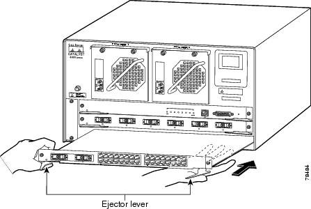
Step 7
Pivot the two module ejector levers out away from the module faceplate.
Step 8
Carefully slide the module into the slot until the notches on both ejector levers engage the chassis sides (the ejector levers start to pivot in towards the faceplate).
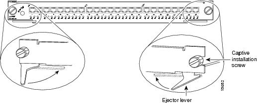
Step 9
Using your thumb and forefinger of each hand, simultaneously pivot in both ejector levers, as shown in Figure 2, to fully seat the module in the backplane connector.
Figure 2 Module Ejector Lever Operation
Caution 
Always use the ejector levers when installing or removing modules. A module that is only partially seated in the backplane causes the system to halt and subsequently crash.
Note
If you perform a hot swap, the console displays the message "Module n has been inserted." This message also appears if you are connected to the Catalyst 4500 series switch through a Telnet session.
Step 10
Use a screwdriver to tighten the captive installation screw on each end of the module faceplate (see Figure 2).
Step 11
Install any necessary transceivers in the module ports. Installation instructions along with safety warnings for the various types of transceivers can be found at the following URL:
http://www.cisco.com/en/US/products/hw/modules/ps5455/prod_installation_guides_list.html
Step 12
Attach any necessary network interface cables or other devices to the interface ports.
Step 13
Check the status of the module as follows:
a.
Ensure that the LED labeled STATUS is green (module operational).
b.
When the switch is on line, enter the show module command. Verify that the system acknowledges the new module and that the module status is good.
Step 14
If the module is not operational, try reseating it in the slot. If the module is still not operational, contact your customer representative.
Removing the Modules
 |
Warning Hazardous voltage or energy is present on the backplane when the system is operating. Use caution when servicing. Statement 1034
|
 |
Warning Invisible laser radiation may be emitted from disconnected fibers or connectors. Do not stare into beams or view directly with optical instruments. Statement 1051
|
You will need a blank module filler plate (C4K-SLOT-CVR-E) if the module slot is to remain empty.
To remove a switching module from a Catalyst 4500 series switch, follow these steps:
Step 1
Disconnect any network interface cables attached to the module ports.
Step 2
If the module is equipped with removable optical transceivers, immediately install dust plugs into the transceiver's optical bores. This prevents possible dust contamination, which can affect port performance.
Step 3
With a Phillips screwdriver, completely loosen the two captive screws located at each end of the module faceplate.
Step 4
Grasp the left and right ejector levers and simultaneously pivot the levers outward to eject the module from the backplane connector.
Step 5
Grasp the module front panel with one hand, and place your other hand under the module (on the metal carrier) to support and guide it out of the slot. Do not touch the printed circuit boards or connector pins.
Step 6
Pull the module straight out of the slot, keeping one hand under the module to support it.
Step 7
Immediately place the removed module on an antistatic mat, in an antistatic bag, or install it in another slot.
 |
Warning Blank faceplates and cover panels serve three important functions: they prevent exposure to hazardous voltages and currents inside the chassis; they contain electromagnetic interference (EMI) that might disrupt other equipment; and they direct the flow of cooling air through the chassis. Do not operate the system unless all cards, faceplates, front covers, and rear covers are in place. Statement 1029
|
Step 8
If the slot is to remain empty, install a blank module filler plate (C4K-SLOT-CVR-E) to keep dust out of the chassis, maintain proper airflow through the chassis, preserve electromagnetic interference (EMI) integrity, and to prevent exposure to high current inside the chassis.
Configuring the Module
To set up the configuration for your switch and module, refer to the software configuration guide for your specific software release at:
http://www.cisco.com/en/US/products/hw/switches/ps4324/products_installation_and_configuration_guides_list.html
Setting Up Power Over Ethernet
To set up Power over Ethernet (PoE) on Catalyst 4500 E-series modules that support PoE, refer to the PoE section in the software configuration guide for your specific software release at:
http://www.cisco.com/en/US/products/hw/switches/ps4324/products_installation_and_configuration_guides_list.html
Obtaining Documentation and Submitting a Service Request
For information on obtaining documentation, submitting a service request, and gathering additional information, see the monthly What's New in Cisco Product Documentation, which also lists all new and revised Cisco technical documentation, at:
http://www.cisco.com/en/US/docs/general/whatsnew/whatsnew.html
Subscribe to the What's New in Cisco Product Documentation as an RSS feed and set content to be delivered directly to your desktop using a reader application. The RSS feeds are a free service. Cisco currently supports RSS Version 2.0.
Cisco and the Cisco logo are trademarks or registered trademarks of Cisco and/or its affiliates in the U.S. and other countries. To view a list of Cisco trademarks, go to this URL: www.cisco.com/go/trademarks. Third-party trademarks mentioned are the property of their respective owners. The use of the word partner does not imply a partnership relationship between Cisco and any other company. (1110R)
© 2011-2012 Cisco Systems, Inc. All rights reserved.