-
null
Configuring DHCP Features
This chapter describes how to configure Dynamic Host Configuration Protocol (DHCP) snooping and the option-82 data insertion features on the Catalyst 3750 switch. Unless otherwise noted, the term switch refers to a standalone switch and to a switch stack.

Note ![]() For complete syntax and usage information for the commands used in this chapter, see the command reference for this release, and refer to the "DHCP Commands" section in the Cisco IOS IP Command Reference, Volume 1 of 3: Addressing and Services, Release 12.2.
For complete syntax and usage information for the commands used in this chapter, see the command reference for this release, and refer to the "DHCP Commands" section in the Cisco IOS IP Command Reference, Volume 1 of 3: Addressing and Services, Release 12.2.
This chapter consists of these sections:
Understanding DHCP Features
DHCP is widely used in LAN environments to dynamically assign host IP addresses from a centralized server, which significantly reduces the overhead of administration of IP addresses. DHCP also helps conserve the limited IP address space because IP addresses no longer need to be permanently assigned to hosts; only those hosts that are connected to the network consume IP addresses.
The switch supports these DHCP features:
•![]() DHCP Snooping and Switch Stacks
DHCP Snooping and Switch Stacks
For information about the DCHP client, refer to the "Configuring DHCP" section of the "IP Addressing and Services" section of the Cisco IOS IP Configuration Guide, Release 12.2.
DHCP Server
The DHCP server assigns IP addresses from specified address pools on a switch or router to DHCP clients and manages them. If the DHCP server cannot give the DHCP client the requested configuration parameters from its database, it can forward the request to one or more secondary DHCP servers defined by the network administrator.
DHCP Relay Agent
A DHCP relay agent is a Layer 3 device that forwards DHCP packets between clients and servers. Relay agents forward requests and replies between clients and servers when they are not on the same physical subnet. Relay agent forwarding is different from the normal Layer 2 forwarding, in which IP datagrams are switched transparently between networks. Relay agents receive DHCP messages and generate new DHCP messages to send on egress interfaces.
DHCP Snooping
DHCP snooping is a DHCP security feature that provides network security by filtering untrusted DHCP messages and by building and maintaining a DHCP snooping binding table. An untrusted message is a message that is received from outside the network or firewall that can cause traffic attacks within your network.When you use DHCP snooping in a service-provider environment, an untrusted message is sent from a device that is not in the service-provider network, such as a customer's switch. Messages from unknown devices are untrusted because they can be sources of traffic attacks.
The DHCP snooping binding table contains the MAC address, the IP address, the lease time, the binding type, the VLAN number, and the interface information that corresponds to the local untrusted interfaces of a switch; it does not contain information regarding hosts interconnected with a trusted interface.
In a service-provider network, a trusted interface is connected to a port on a device in the same network. An untrusted interface is connected to an untrusted interface in the network or to a interface on a device that is not in the network.
DHCP snooping acts like a firewall between untrusted hosts and DHCP servers. It also gives you a way to differentiate between untrusted interfaces connected to the end user and trusted interfaces connected to the DHCP server or another switch. For DHCP snooping to function properly, all DHCP servers must be connected to the switch through trusted interfaces.
When a switch receives a packet on an untrusted interface and the interface belongs to a VLAN in which DHCP snooping is enabled, it verifies that the source MAC address and the DHCP client hardware address match (the default). If the addresses match, the switch forwards the packet. If the addresses do not match, the switch drops the packet.
Option-82 Data Insertion
In residential, metropolitan Ethernet-access environments, DHCP can centrally manage the IP address assignments for a large number of subscribers. When the DHCP option-82 feature is enabled on the switch, a subscriber device is identified by the switch port through which it connects to the network (in addition to its MAC address). Multiple hosts on the subscriber LAN can be connected to the same port on the access switch and are uniquely identified.
Note ![]() The DHCP option-82 feature is supported only when DHCP snooping is enabled globally and on the VLANs to which subscriber devices using this feature are assigned.
The DHCP option-82 feature is supported only when DHCP snooping is enabled globally and on the VLANs to which subscriber devices using this feature are assigned.
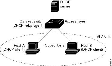
Figure 19-1 is an example of a metropolitan Ethernet network in which a centralized DHCP server assigns IP addresses to subscribers connected to the switch at the access layer. Because the DHCP clients and their associated DHCP server do not reside on the same IP network or subnet, a DHCP relay agent (the Catalyst switch) is configured with a helper address to enable broadcast forwarding and to transfer DHCP messages between the clients and the server.
Figure 19-1 DHCP Relay Agent in a Metropolitan Ethernet Network
When you enable the DHCP snooping information option 82 on the switch, this sequence of events occurs:
•![]() The host (DHCP client) generates a DHCP request and broadcasts it on the network.
The host (DHCP client) generates a DHCP request and broadcasts it on the network.
•![]() When the switch receives the DHCP request, it adds the option-82 information in the packet. The option-82 information contains the switch MAC address (the remote ID suboption) and the port identifier, vlan-mod-port, from which the packet is received (the circuit ID suboption).
When the switch receives the DHCP request, it adds the option-82 information in the packet. The option-82 information contains the switch MAC address (the remote ID suboption) and the port identifier, vlan-mod-port, from which the packet is received (the circuit ID suboption).
•![]() If the IP address of the relay agent is configured, the switch adds this IP address in the DHCP packet.
If the IP address of the relay agent is configured, the switch adds this IP address in the DHCP packet.
•![]() The switch forwards the DHCP request that includes the option-82 field to the DHCP server.
The switch forwards the DHCP request that includes the option-82 field to the DHCP server.
•![]() The DHCP server receives the packet. If the server is option-82-capable, it can use the remote ID, the circuit ID, or both to assign IP addresses and implement policies, such as restricting the number of IP addresses that can be assigned to a single remote ID or circuit ID. Then the DHCP server echoes the option-82 field in the DHCP reply.
The DHCP server receives the packet. If the server is option-82-capable, it can use the remote ID, the circuit ID, or both to assign IP addresses and implement policies, such as restricting the number of IP addresses that can be assigned to a single remote ID or circuit ID. Then the DHCP server echoes the option-82 field in the DHCP reply.
•![]() The DHCP server unicasts the reply to the switch if the request was relayed to the server by the switch. The switch verifies that it originally inserted the option-82 data by inspecting the remote ID and possibly the circuit ID fields. The switch removes the option-82 field and forwards the packet to the switch port that connects to the DHCP client that sent the DHCP request.
The DHCP server unicasts the reply to the switch if the request was relayed to the server by the switch. The switch verifies that it originally inserted the option-82 data by inspecting the remote ID and possibly the circuit ID fields. The switch removes the option-82 field and forwards the packet to the switch port that connects to the DHCP client that sent the DHCP request.
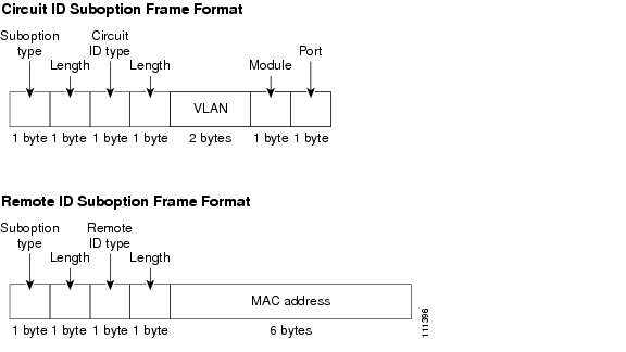
Figure 19-2 shows the packet formats for the remote ID suboption and the circuit ID suboption. For the circuit ID suboption, the module number corresponds to the switch number in the stack. The switch uses the packet formats when DHCP snooping is globally enabled and when the ip dhcp snooping information option global configuration command is entered.
Figure 19-2 Suboption Packet Formats
DHCP Snooping and Switch Stacks
DHCP snooping is managed on the stack master. When a new switch joins the stack, the switch receives the DHCP snooping configuration from the stack master. When a member leaves the stack, all DHCP snooping address bindings associated with the switch age out.
When a stack merge occurs, all DHCP snooping bindings in the stack master are lost if it is no longer the stack master. With a stack partition, the existing stack master is unchanged, and the bindings belonging to the partitioned switches age out. The new master of the partitioned stack begins processing the new incoming DHCP packets. For more information about switch stacks, see "Managing Switch Stacks."
Configuring DHCP Features
These sections describe how to configure the DHCP server, the DHCP relay agent, DHCP snooping, and option 82 on your switch:
•![]() DHCP Snooping Configuration Guidelines
DHCP Snooping Configuration Guidelines
•![]() DHCP Server and Switch Stacks
DHCP Server and Switch Stacks
•![]() Configuring the DHCP Relay Agent
Configuring the DHCP Relay Agent
•![]() Specifying the Packet Forwarding Address
Specifying the Packet Forwarding Address
•![]() Enabling DHCP Snooping and Option 82
Enabling DHCP Snooping and Option 82
Default DHCP Configuration
Table 19-1 shows the default DHCP configuration.
|
|
|
|---|---|
DHCP server |
Enabled1 |
DHCP relay agent |
Enabled2 |
DHCP packet forwarding address |
None configured |
Checking the relay agent information |
Enabled (invalid messages are dropped)2 |
DHCP relay agent forwarding policy |
Replace the existing relay agent information2 |
DHCP snooping enabled globally |
Disabled |
DHCP snooping information option |
Enabled |
DHCP snooping limit rate |
None configured |
DHCP snooping trust |
Untrusted |
DHCP snooping VLAN |
Disabled |
DHCP snooping MAC address verification |
Enabled |
1 The switch responds to DHCP requests only if it is configured as a DHCP server. 2 The switch relays DHCP packets only if the IP address of the DHCP server is configured on the SVI of the DHCP client. |
DHCP Snooping Configuration Guidelines
These are the configuration guidelines for DHCP snooping.
•![]() You must globally enable DHCP snooping on the switch.
You must globally enable DHCP snooping on the switch.
•![]() DHCP snooping is not active until DHCP snooping is enabled on a VLAN.
DHCP snooping is not active until DHCP snooping is enabled on a VLAN.
•![]() Before globally enabling DHCP snooping on the switch, make sure that the devices acting as the DHCP server and the DHCP relay agent are configured and enabled.
Before globally enabling DHCP snooping on the switch, make sure that the devices acting as the DHCP server and the DHCP relay agent are configured and enabled.
•![]() When you globally enable DHCP snooping on the switch, these Cisco IOS commands are not available until snooping is disabled. If you enter these commands, the switch returns an error message, and the configuration is not applied.
When you globally enable DHCP snooping on the switch, these Cisco IOS commands are not available until snooping is disabled. If you enter these commands, the switch returns an error message, and the configuration is not applied.
–![]() ip dhcp relay information check global configuration command
ip dhcp relay information check global configuration command
–![]() ip dhcp relay information policy global configuration command
ip dhcp relay information policy global configuration command
–![]() ip dhcp relay information trust-all global configuration command
ip dhcp relay information trust-all global configuration command
–![]() ip dhcp relay information trusted interface configuration command
ip dhcp relay information trusted interface configuration command
•![]() Before configuring the DHCP snooping information option on your switch, be sure to configure the device that is acting as the DHCP server. For example, you must specify the IP addresses that the DHCP server can assign or exclude, or you must configure DHCP options for these devices.
Before configuring the DHCP snooping information option on your switch, be sure to configure the device that is acting as the DHCP server. For example, you must specify the IP addresses that the DHCP server can assign or exclude, or you must configure DHCP options for these devices.
•![]() Before configuring the DHCP relay agent on your switch, make sure to configure the device that is acting as the DHCP server. For example, you must specify the IP addresses that the DHCP server can assign or exclude, configure DHCP options for devices, or set up the DHCP database agent.
Before configuring the DHCP relay agent on your switch, make sure to configure the device that is acting as the DHCP server. For example, you must specify the IP addresses that the DHCP server can assign or exclude, configure DHCP options for devices, or set up the DHCP database agent.
•![]() If the DHCP relay agent is enabled but DHCP snooping is disabled, the DHCP option-82 data insertion feature is not supported.
If the DHCP relay agent is enabled but DHCP snooping is disabled, the DHCP option-82 data insertion feature is not supported.
•![]() If a switch port is connected to a DHCP server, configure a port as trusted by entering the ip dhcp snooping trust interface configuration command.
If a switch port is connected to a DHCP server, configure a port as trusted by entering the ip dhcp snooping trust interface configuration command.
•![]() If a switch port is connected to a DHCP client, configure a port as untrusted by entering the no ip dhcp snooping trust interface configuration command.
If a switch port is connected to a DHCP client, configure a port as untrusted by entering the no ip dhcp snooping trust interface configuration command.
Configuring the DHCP Server
The switch can act as a DHCP server. By default, the Cisco IOS DHCP server and relay agent features are enabled on your switch but are not configured. These features are not operational.
For procedures to configure the switch as a DHCP server, refer to the "Configuring DHCP" section of the "IP addressing and Services" section of the Cisco IOS IP Configuration Guide, Release 12.2.
DHCP Server and Switch Stacks
The DHCP binding database is managed on the stack master. When a new stack master is assigned, the new master downloads the saved binding database from the TFTP server. If the stack master fails, all unsaved bindings are lost. The IP addresses associated with the lost bindings are released. You should configure an automatic backup by using the ip dhcp database url [timeout seconds | write-delay seconds] global configuration command.
When a stack merge occurs, the stack master that becomes a stack member loses all of the DHCP lease bindings. With a stack partition, the new master in the partition acts as a new DHCP server without any of the existing DHCP lease bindings.
For more information about the switch stack, see "Managing Switch Stacks."
Configuring the DHCP Relay Agent
Beginning in privileged EXEC mode, follow these steps to enable the DHCP relay agent on the switch:
To disable the DHCP server and relay agent, use the no service dhcp global configuration command.
Refer to the "Configuring DHCP" section of the "IP Addressing and Services" section of the Cisco IOS IP Configuration Guide, Release 12.2 for these procedures:
•![]() Checking (validating) the relay agent information
Checking (validating) the relay agent information
•![]() Configuring the relay agent forwarding policy
Configuring the relay agent forwarding policy
Specifying the Packet Forwarding Address
If the DHCP server and the DHCP clients are on different networks or subnets, you must configure the switch with the ip helper-address address interface configuration command. The general rule is to configure the command on the Layer 3 interface closest to the client. The address used in the ip helper-address command can be a specific DHCP server IP address, or it can be the network address if other DHCP servers are on the destination network segment. Using the network address enables any DHCP server to respond to requests.
Beginning in privileged EXEC mode, follow these steps to specify the packet forwarding address:
To remove the DHCP packet forwarding address, use the no ip helper-address address interface configuration command.
Enabling DHCP Snooping and Option 82
Beginning in privileged EXEC mode, follow these steps to enable DHCP snooping on the switch.
To disable DHCP snooping, use the no ip dhcp snooping global configuration command. To disable DHCP snooping on a VLAN or range of VLANs, use the no ip dhcp snooping vlan vlan-range global configuration command. To disable the insertion and removal of the option-82 field, use the no ip dhcp snooping information option global configuration command.
This example shows how to enable DHCP snooping globally and on VLAN 10 and to configure a rate limit of 100 packets per second on a port:
Switch(config)# ip dhcp snooping
Switch(config)# ip dhcp snooping vlan 10
Switch(config)# ip dhcp snooping information option
Switch(config)# interface gigabitethernet2/0/1
Switch(config-if)# ip dhcp snooping limit rate 100
Displaying DHCP Information
You can display a DHCP snooping binding table and configuration information for all interfaces on a switch.
Displaying a Binding Table
The DHCP snooping binding table for each switch has binding entries that correspond to untrusted ports. The table does not have information about hosts interconnected with a trusted port.
This example shows how to display the DHCP snooping binding entries for a switch.
Switch# show ip dhcp snooping binding
MacAddress IpAddress Lease(sec) Type VLAN Interface
------------------ --------------- ---------- ------------- ---- --------------------
01:02:03:04:05:06 10.1.2.150 9837 dhcp-snooping 20 GigabitEthernet2/0/1
00:D0:B7:1B:35:DE 10.1.2.151 237 dhcp-snooping 20 GigabitEthernet2/0/1
00:00:00:00:00:01 40.0.0.46 286 dhcp-snooping 20 GigabitEthernet2/0/2
00:00:00:00:00:03 42.0.0.33 286 dhcp-snooping 22 GigabitEthernet2/0/2
00:00:00:00:00:02 41.0.0.53 286 dhcp-snooping 21 GigabitEthernet2/0/2
Table 19-2 describes the fields in the show ip dhcp snooping binding command output.
Displaying the DHCP Snooping Configuration
This example shows how to display the DHCP snooping configuration for a switch.
Switch# show ip dhcp snooping
Switch DHCP snooping is enabled
DHCP snooping is configured on following VLANs:
40-42
Insertion of option 82 is enabled
Verification of hwaddr field is enabled
Interface Trusted Rate limit (pps)
------------------------ ------- ----------------
gigabitethernet1/0/1 yes unlimited
gigabitethernet2/0/2 no 100
gigabitethernet2/0/3 yes unlimited
gigabitethernet2/0/4 yes unlimited
 Feedback