Feedback
Table Of Contents
Creating a Zone and Adding It to a Zone Set (Standalone Method)
Creating a Zone and Adding It to a Zone Set (Inline Method)
Creating a Fibre Channel Alias Based Zone
Creating an Interface Based Zone
Automatic Zone Set Distribution
Zoning
Zones and zone sets are the basic form of data path security within a Fibre Channel environment. A zone set is a collection of zones which in turn have individual members in them. Only those members within the same zone can communicate with each other. A device can be a member of multiple zones and those devices not in a zone are in the default zone. The policy for the default zone can either be to permit devices to see each other or to deny devices in the default zone from seeing each other.
This chapter focuses on the creation of zones, zone sets, and ways to manipulate them. It includes the following sections:
Zones
In order for two devices to communicate, they must be in the same zone. Valid members of a zone can be:
•
Port WWN (pWWN)
•
•
•
•
•
The three most common types of zone members are pWWN, FC alias, and the switch interface.
Tip
The name that you choose for the zone is very important. Many environments use different zone names, however, all name formats should provide relevant information as to their contents. Names like Zone1 or TapeZone do not provide sufficient information about their contents.
A zone name should contain two members and, within the zone name, contain identifiers related to the two devices, such as Z_testhost_fcaw0_symm13FA3aa. The name may be longer than Z_testhost_hba0, but should provide enough detailed information about the contents that consulting further documentation is not necessary.
Creating a Zone and Adding It to a Zone Set (Standalone Method)
This procedure demonstrates how to create a single zone with a Solaris host and a disk storage port in it, and then add it to the zone set ZS_Engr_primary. The procedure uses the standalone method, which does not automatically add the zone to the zone set upon creation of the zone. You can also use this procedure to determine how to add an existing zone to a zone set.
This example uses pWWNs as the zone members, which can be obtained either from the device itself or from the show flogi database vsan 804 command. (See Figure 7-1.)
Resources:
Zone set: ZS_Engr_primary
Solaris host1, hba instance fcaw0: 22:35:00:0c:85:e9:d2:c2
Symmetrix 78, FA port 03ab: 10:00:00:00:c9:32:8b:a8
Figure 7-1 Standalone Zoning Topology
To create a single zone and add it to a zone set using the standalone method, follow these steps:
Step 1
ca-9506# config terminalEnter configuration commands, one per line. End with CNTL/Z.ca-9506(config)# zone name Z_host1_fcaw0_symm78FA03ab vsan 804ca-9506(config-zone)# member pwwn 22:35:00:0c:85:e9:d2:c2ca-9506(config-zone)# member pwwn 10:00:00:00:c9:32:8b:a8Step 2
ca-9506(config)# zoneset name ZS_Engr_primary vsan 804ca-9506(config-zoneset)# member Z_host1_fcaw0_symm78FA03abStep 3
ca-9506# show zoneset name ZS_Engr_primary vsan 804zoneset name ZS_Engr_primary vsan 804zone name Z_host1_fcaw0_symm78FA03ab vsan 804pwwn 22:35:00:0c:85:e9:d2:c2pwwn 10:00:00:00:c9:32:8b:a8Step 4
Creating a Zone and Adding It to a Zone Set (Inline Method)
This procedure demonstrates how to create a single zone with a Solaris host and a disk storage port in it, and add it to the zone set ZS_Engr_primary. The procedure uses the inline method, which automatically adds the zone to the zone set upon creation of the zone.
This example uses pWWNs as the zone members, which can be obtained either from the device itself or from the show flogi database vsan 804 command. (See Figure 7-2.)
Resources:
Zone set: ZS_Engr_primary
Solaris host1, hba instance fcaw0: 22:35:00:0c:85:e9:d2:c2
Symmetrix 78, FA port 03ab: 10:00:00:00:c9:32:8b:a8
Figure 7-2 Inline Zoning Topology
To create a single zone and add it to a zone set using the inline method, follow these steps:
Step 1
ca-9506# config terminalEnter configuration commands, one per line. End with CNTL/Z.ca-9506(config)# zoneset name ZS_Engr_primary vsan 804Step 2
ca-9506(config-zoneset)# zone name Z_host1_fcaw0_symm78FA03abStep 3
ca-9506(config-zoneset-zone)# member pwwn 22:35:00:0c:85:e9:d2:c2ca-9506(config-zoneset-zone)# member pwwn 10:00:00:00:c9:32:8b:a8Step 4
ca-9506# show zoneset name ZS_Engr_primary vsan 804zoneset name ZS_Engr_primary vsan 804zone name Z_host1_fcaw0_symm78FA03ab vsan 804pwwn 22:35:00:0c:85:e9:d2:c2pwwn 10:00:00:00:c9:32:8b:a8Step 5
Creating a Fibre Channel Alias Based Zone
Fibre Channel aliases allow the administrator to assign a plain text, human readable name to a pWWN, FC ID, interface, IP address, nWWN or symbolic node name. Fibre Channel aliases are restricted to the VSAN in which they were created. The most common and recommended Fibre Channel alias is the pWWN, which is the basis for this procedure. (See Figure 7-3.)
Tip
•
Resources:
Zone set: ZS_Engr_primary
Solaris host1, hba instance fcaw0: 22:35:00:0c:85:e9:d2:c2
Symmetrix 78, FA port 03ab: 10:00:00:00:c9:32:8b:a8
Figure 7-3 Alias Zoning Topology
To create a Fibre Channel alias based zone, follow these steps:
Step 1
ca-9506# config terminalEnter configuration commands, one per line. End with CNTL/Z.ca-9506(config)# fcalias name host1_fcaw0 vsan 804ca-9506(config-fcalias)# member pwwn 22:35:00:0c:85:e9:d2:c2ca-9506(config-fcalias)# exitca-9506(config)# fcalias name symm78_fa03ab vsan 804ca-9506(config-fcalias)# member pwwn 10:00:00:00:c9:32:8b:a8ca-9506(config-fcalias)# endStep 2
ca-9506# show fcalias vsan 804fcalias name host1_fcaw0 vsan 804pwwn 22:35:00:0c:85:e9:d2:c2fcalias name symm78_fa03ab vsan 804pwwn 10:00:00:00:c9:32:8b:a8Step 3
ca-9506# config terminalEnter configuration commands, one per line. End with CNTL/Z.ca-9506(config)# zoneset name ZS_Engr_primary vsan 804ca-9506(config-zoneset)# zone name Z_host1_fcaw0_symm78FA03abca-9506(config-zoneset-zone)# member fcalias host1_fcaw0ca-9506(config-zoneset-zone)# member fcalias symm78_fa03abStep 4
ca-9506# show zoneset vsan 804zoneset name ZS_Engr_primary vsan 804zone name Z_host1_fcaw0_symm78FA03ab vsan 804fcalias name host1_fcaw0 vsan 804pwwn 22:35:00:0c:85:e9:d2:c2fcalias name symm78_fa03ab vsan 804pwwn 10:00:00:00:c9:32:8b:a8Step 5
ca-9506# conf tEnter configuration commands, one per line. End with CNTL/Z.ca-9506(config)# zoneset activate name ZS_Engr_primary vsan 804Zoneset activation initiated. check zone status
Creating an Interface Based Zone
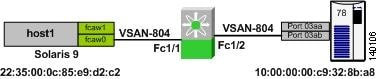
This procedure describes how to create a zone based upon the physical interface (fc X/Y) of the switch. (See Figure 7-4.)
Tip
Figure 7-4 Interface Zoning Topology
To create a zone based on the physical interface of the switch, follow these steps:
Step 1
ca-9506# config terminalEnter configuration commands, one per line. End with CNTL/Z.ca-9506(config)# zoneset name ZS_Engr_primary vsan 804ca-9506(config-zoneset)# zone name Z_host1_fcaw0_symm78FA03abca-9506(config-zoneset-zone)# member interface fc1/1ca-9506(config-zoneset-zone)# member interface fc1/2Step 2
ca-9506# show zoneset vsan 804zoneset name ZS_Engr_primary vsan 804zone name Z_host1_fcaw0_symm78FA03ab vsan 804interface fc1/1 swwn 20:00:00:0c:85:e9:d2:c0interface fc1/2 swwn 20:00:00:0c:85:e9:d2:c0
Note
ca-9506# show wwn switch
Switch WWN is 20:00:00:0c:85:e9:d2:c0Step 3
ca-9506# conf tEnter configuration commands, one per line. End with CNTL/Z.ca-9506(config)# zoneset activate name ZS_Engr_primary vsan 804Zoneset activation initiated. check zone status
Zone Sets
Zone sets are containers of zones. There are two zone set types on the Cisco MDS 9000 platform:
•
•
Zone Set Distribution
There are two distribution methods for zone sets: automatic and manual.
Automatic Zone Set Distribution
To enable the switch to distribute the local zone set to all other switches in the VSAN when a zone set is activated, use the zone set distribute full vsan 804 command:
ca-9506# conf tEnter configuration commands, one per line. End with CNTL/Z.ca-9506(config)# zoneset distribute full vsan 804
Tip
Manual Zone Set Distribution
To distribute the full zone set database to other switches without activating a zone set, use the zone set distribute vsan 804 command. This method can be effective when a new switch is brought into the fabric and the zone set with its zones and Fibre Channel aliases needs to be distributed. This command will overwrite the exiting zone set database in the target switch.
ca-9506# zoneset distribute vsan 804Zoneset distribution initiated. check zone status