Feedback
Table Of Contents
Saving the Switch Configuration
Copying Files to or from the MDS 9000 Switch
Managing Files on the Standby Supervisor Module
Upgrading MDS 9000 Switch Firmware
Upgrading Switch Firmware Using the CLI
Upgrading Switch Firmware Using Fabric Manager
Using the CLI to Install a License
Using Fabric Manager to Install a License
Copying Core Files from the MDS 9000 Switch
Restoring a Fixed Switch Configuration
Switch Management
This chapter describes various tasks associated with managing a Cisco MDS 9000 switch and includes the following sections:
•
Saving the Switch Configuration
•
•
•
•
•
Saving the Switch Configuration
Saving the configuration after making changes to the Cisco MDS 9000 switch is always a good idea. Whether creating users or configuring ports, the configuration should be saved so that if the switch is rebooted, the current configuration is reapplied to the switch. Optionally, the configuration should also be saved to a file server for purposes of archival, disaster recovery, or version control.
The MDS 9000 switch has two configuration files:
•
•
Both configuration files can be viewed using the show running-configuration command or show startup-configuration command.
Tip
To save the running-configuration, copy it to the startup-configuration:
ca-9506# copy running-config startup-config[########################################] 100%To copy the startup-configuration to a remote server (in this example the server is SCP), modify the destination filename, by providing a filename to use on the file server (switch1.startupconfig.01182004).
ca-9506# copy startup-config scp://user@fileserver/switch1.startup.01182004setmason@dino's password:sysmgr_system.cfg 100% |*****************************| 16276 00:00Now the file can be viewed in the switch1.startup.01182004 file.
Copying Files to or from the MDS 9000 Switch
You may need to move files to or from a Cisco MDS 9000 switch. The types of files you may need to move include log files, configuration files, or firmware files. There are two methods for copying files to or from the MDS 9000 switch: using the CLI (command-line interface) and using Fabric Manager.
The first procedure covers the CLI.
The CLI offers a broad range of protocols to use for copying to or from the MDS 9000 switch. Note that the MDS 9000 switch always acts as a client, such that an FTP/SCP/TFTP session always originates from the MDS 9000 switch and either pushes files to an external system or pulls files from an external system.
File Server: 172.22.36.10
File to be copied to the switch: /etc/hosts
The copy command supports four transfer protocols and 12 different sources for files.
ca-9506# copy ?bootflash: Select source filesystemcore: Select source filesystemdebug: Select source filesystemftp: Select source filesystemlicenses Backup license fileslog: Select source filesystemmodflash: Select source filesystemnvram: Select source filesystemrunning-config Copy running configuration to destinationscp: Select source filesystemsftp: Select source filesystemslot0: Select source filesystemstartup-config Copy startup configuration to destinationsystem: Select source filesystemtftp: Select source filesystemvolatile: Select source filesystemTo use SCP (Secure copy) as the transfer mechanism, the syntax is as follows:
scp:[//[username@]server][/path]
To copy /etc/hosts from 172.22.36.10 using user1as the user and the destination filename hosts.txt, enter the following command:
switch# copy scp://user1@172.22.36.10/etc/hosts bootflash:hosts.txtuser1@172.22.36.10's password:hosts 100% |*****************************| 2035 00:00To back up the startup-configuration to a SFTP server, enter the following command:
switch# copy startup-config sftp://user1@172.22.36.10/MDS/startup-configuration.bak1Connecting to 172.22.36.10...User1@172.22.36.10's password:switch#
Tip
Managing Files on the Standby Supervisor Module
Occasionally, a file may need to be copied to, copied off, or deleted from the supervisor module, or even deleted from the standby supervisor module. To do this, attach to the standby supervisor module and use the dir and delete commands.
Note
To perform file copy functions from the supervisor module, follow these steps:
Step 1
switch# show moduleMod Ports Module-Type Model Status--- ----- ------------------------------- ------------------ ------------1 16 1/2 Gbps FC Module DS-X9016 ok2 16 1/2 Gbps FC Module DS-X9016 ok3 8 IP Storage Services Module DS-X9308-SMIP ok4 0 Caching Services Module DS-X9560-SMAP ok5 0 Supervisor/Fabric-1 DS-X9530-SF1-K9 active *6 0 Supervisor/Fabric-1 DS-X9530-SF1-K9 ha-standbyStep 2
ca-9506# attach module 6Attaching to module 6 ...To exit type 'exit', to abort type '$.'Cisco Storage Area Networking Operating System (SAN-OS) SoftwareTAC support: http://www.cisco.com/tacCopyright (c) 2002-2004, Cisco Systems, Inc. All rights reserved.The copyrights to certain works contained herein are owned byAndiamo Systems, Inc. and/or other third parties and are used anddistributed under license. Some parts of this software are coveredunder the GNU Public License. A copy of the license is availableat http://www.gnu.org/licenses/gpl.html.ca-9506(standby)#Step 3
ca-9506(standby)# dir bootflash:12330496 Jun 30 21:11:33 2004 boot-1-3-4a2035 Jun 17 16:30:18 2004 hosts.txt43705437 Jun 30 21:11:58 2004 isan-1-3-4a12288 Dec 31 17:13:48 1979 lost+found/12334592 Jun 23 17:02:16 2004 m9500-sf1ek9-kickstart-mz.1.3.4b.bin43687917 Jun 23 17:02:42 2004 m9500-sf1ek9-mz.1.3.4b.bin99 Apr 07 19:28:54 1980 security_cnv.logUsage for bootflash://sup-local126340096 bytes used59745280 bytes free186085376 bytes totalStep 4
ca-9506(standby)# delete bootflash:hosts.txtStep 5
ca-9506(standby)# exitrlogin: connection closed.ca-9506#
Upgrading MDS 9000 Switch Firmware
To obtain new features and functionality for a Cisco MDS 9000 switch, you may need to upgrade the firmware. You can upgrade using either the CLI or the Fabric Manager.
Firmware images can be downloaded from the Cisco software center located at the following URL: http://www.cisco.com/public/sw-center/sw-stornet.shtml. A CCO login account is required to download all software images.
Tip
In this procedure the firmware images have been downloaded from the Cisco website and are located on a local file server.
File server: testhost
System image: m9500-sf1ek9-mz.1.3.4b.bin
Kickstart image: m9500-sf1ek9-kickstart-mz.1.3.4b.bin
The location of the firmware images may either be on the switch's bootflash: file system or on another server accessible via FTP/TFTP/SFTP/SCP.
Upgrading Switch Firmware Using the CLI
To upgrade the firmware of an MDS 9000 switch using SCP, enter the following CLI commands:
Step 1
ca-9506# show install all impact system
scp://setmason@testhost/tftpboot/rel/qa/1_3_4b/final/m95
00-sf1ek9-mz.1.3.4b.bin kickstart scp://setmason@testhost /tftpboot/rel/qa/1_3_4b/final/m9500-sf1ek9-kickstart-mz.1.3.4b.binFor scp://setmason@testhost, please enter password:For scp://setmason@testhost, please enter password:Copying image from scp://setmason@testhost /tftpboot/rel/qa/1_3_4b/final/m9500-sf1ek9-kickstart-mz.1.3.4b.bin to bootflash:///m9500-sf1ek9-kickstart-mz.1.3.4b.bin.[####################] 100% -- SUCCESSCopying image from scp://setmason@testhost /tftpboot/rel/qa/1_3_4b/final/m9500-sf1ek9-mz.1.3.4b.bin to bootflash:///m9500-sf1ek9-mz.1.3.4b.bin.[####################] 100% -- SUCCESSVerifying image bootflash:///m9500-sf1ek9-kickstart-mz.1.3.4b.bin[####################] 100% -- SUCCESSVerifying image bootflash:///m9500-sf1ek9-mz.1.3.4b.bin[####################] 100% -- SUCCESSExtracting "slc" version from image bootflash:///m9500-sf1ek9-mz.1.3.4b.bin.[####################] 100% -- SUCCESSExtracting "ips" version from image bootflash:///m9500-sf1ek9-mz.1.3.4b.bin.[####################] 100% -- SUCCESSExtracting "svclc" version from image bootflash:///m9500-sf1ek9-mz.1.3.4b.bin.[####################] 100% -- SUCCESSExtracting "system" version from image bootflash:///m9500-sf1ek9-mz.1.3.4b.bin.[####################] 100% -- SUCCESSExtracting "kickstart" version from image bootflash:///m9500-sf1ek9-kickstart-mz.1.3.4b.bin.[####################] 100% -- SUCCESSExtracting "loader" version from image bootflash:///m9500-sf1ek9-kickstart-mz.1.3.4b.bin.[####################] 100% -- SUCCESSCompatibility check is done:Module bootable Impact Install-type Reason------ -------- -------------- ------------ ------1 yes non-disruptive rolling2 yes non-disruptive rolling3 yes non-disruptive rolling4 yes non-disruptive rolling5 yes non-disruptive reset6 yes non-disruptive resetOther miscellaneous information for installation:Module info------ ----------------------------------Images will be upgraded according to following table:Module Image Running-Version New-Version Upg-Required------ ---------- -------------------- -------------------- ---------1 slc 1.3(4a) 1.3(4b) yes1 bios v1.1.0(10/24/03) v1.0.8(08/07/03) no2 slc 1.3(4a) 1.3(4b) yes2 bios v1.0.8(08/07/03) v1.0.8(08/07/03) no3 ips 1.3(4a) 1.3(4b) yes3 bios v1.0.8(08/07/03) v1.0.8(08/07/03) no4 svclc 1.3(4a) 1.3(4b) yes4 svcsb 1.3(4m) 1.3(4m) no4 svcsb 1.3(4) 1.3(4) no4 bios v1.1.0(10/24/03) v1.0.8(08/07/03) no5 system 1.3(4a) 1.3(4b) yes5 kickstart 1.3(4a) 1.3(4b) yes5 bios v1.1.0(10/24/03) v1.0.8(08/07/03) no5 loader 1.2(2) 1.2(2) no6 system 1.3(4a) 1.3(4b) yes6 kickstart 1.3(4a) 1.3(4b) yes6 bios v1.1.0(10/24/03) v1.0.8(08/07/03) no6 loader 1.2(2) 1.2(2) noStep 2
ca-9506# install all system scp://setmason@testhost/tftpboot/rel/qa/1_3_4b/final/m9500-sf1ek9-mz.1.3.4b.bin kickstart scp://setmason@testhost /tftpboot/rel/qa/1_3_4b/final/m9500-sf1ek9-kickstart-mz.1.3.4b.binFor scp://setmason@testhost, please enter password:For scp://setmason@testhost, please enter password:Copying image from scp://setmason@testhost /tftpboot/rel/qa/1_3_4b/final/m9500-sf1ek9-kickstart-mz.1.3.4b.bin to bootflash:///m9500-sf1ek9-kickstart-mz.1.3.4b.bin.[####################] 100% -- SUCCESSCopying image from scp://setmason@testhost /tftpboot/rel/qa/1_3_4b/final/m9500-sf1ek9-mz.1.3.4b.bin to bootflash:///m9500-sf1ek9-mz.1.3.4b.bin.[####################] 100% -- SUCCESSVerifying image bootflash:///m9500-sf1ek9-kickstart-mz.1.3.4b.bin[####################] 100% -- SUCCESSVerifying image bootflash:///m9500-sf1ek9-mz.1.3.4b.bin[####################] 100% -- SUCCESSExtracting "slc" version from image bootflash:///m9500-sf1ek9-mz.1.3.4b.bin.[####################] 100% -- SUCCESSExtracting "ips" version from image bootflash:///m9500-sf1ek9-mz.1.3.4b.bin.[####################] 100% -- SUCCESSExtracting "svclc" version from image bootflash:///m9500-sf1ek9-mz.1.3.4b.bin.[####################] 100% -- SUCCESSExtracting "system" version from image bootflash:///m9500-sf1ek9-mz.1.3.4b.bin.[####################] 100% -- SUCCESSExtracting "kickstart" version from image bootflash:///m9500-sf1ek9-kickstart-mz.1.3.4b.bin.[####################] 100% -- SUCCESSExtracting "loader" version from image bootflash:///m9500-sf1ek9-kickstart-mz.1.3.4b.bin.[####################] 100% -- SUCCESSCompatibility check is done:Module bootable Impact Install-type Reason------ -------- -------------- ------------ ------1 yes non-disruptive rolling2 yes non-disruptive rolling3 yes non-disruptive rolling4 yes non-disruptive rolling5 yes non-disruptive reset6 yes non-disruptive resetOther miscellaneous information for installation:Module info------ ----------------------------------Images will be upgraded according to following table:Module Image Running-Version New-Version Upg-Required------ ---------- -------------------- -------------------- ---------1 slc 1.3(4a) 1.3(4b) yes1 bios v1.1.0(10/24/03) v1.0.8(08/07/03) no2 slc 1.3(4a) 1.3(4b) yes2 bios v1.0.8(08/07/03) v1.0.8(08/07/03) no3 ips 1.3(4a) 1.3(4b) yes3 bios v1.0.8(08/07/03) v1.0.8(08/07/03) no4 svclc 1.3(4a) 1.3(4b) yes4 svcsb 1.3(4m) 1.3(4m) no4 svcsb 1.3(4) 1.3(4) no4 bios v1.1.0(10/24/03) v1.0.8(08/07/03) no5 system 1.3(4a) 1.3(4b) yes5 kickstart 1.3(4a) 1.3(4b) yes5 bios v1.1.0(10/24/03) v1.0.8(08/07/03) no5 loader 1.2(2) 1.2(2) no6 system 1.3(4a) 1.3(4b) yes6 kickstart 1.3(4a) 1.3(4b) yes6 bios v1.1.0(10/24/03) v1.0.8(08/07/03) no6 loader 1.2(2) 1.2(2) noDo you want to continue with the installation (y/n)? [n] yInstall is in progress, please wait.Syncing image bootflash:///m9500-sf1ek9-kickstart-mz.1.3.4b.bin to standby.[####################] 100% -- SUCCESSSyncing image bootflash:///m9500-sf1ek9-mz.1.3.4b.bin to standby.[####################] 100% -- SUCCESSSetting boot variables.[####################] 100% -- SUCCESSPerforming configuration copy.[####################] 100% -- SUCCESSModule 5: Waiting for module online.-- SUCCESSAt this point, the switch performs a hitless supervisor switchover. A new Telnet/CLI session must be established to the new supervisor.
Note
Step 3
switch# show install all statusThis is the log of last installation.Continue on installation process, please wait.The login will be disabled until the installation is completed.Module 5: Waiting for module online.-- SUCCESSModule 1: Non-disruptive upgrading.-- SUCCESSModule 2: Non-disruptive upgrading.-- SUCCESSModule 3: Non-disruptive upgrading.-- SUCCESSModule 4: Non-disruptive upgrading.-- SUCCESSInstall has been successful.
Upgrading Switch Firmware Using Fabric Manager
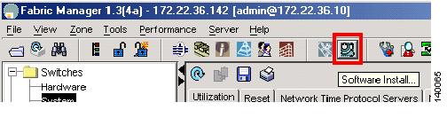
To upgrade the firmware of one or more MDS 9000 switches, leverage the interface of the Fabric Manager and follow these steps:
Step 1
Figure 2-1 Image Installation with Fabric Manager
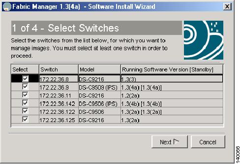
Step 2
Figure 2-2 Choose Switches to Upgrade
Step 3
a.
b.
c.
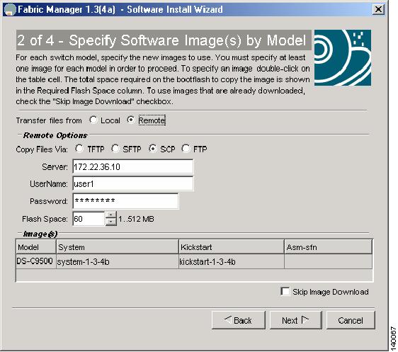
Figure 2-3 Specify Firmware Images
Step 4
Depending on the installation method (that is, already downloaded to bootflash or download during the install), the wizard may prompt for additional file locations. The fourth and final screen provides a summary and enables you to start the install. During the installation, a compatibility screen pops up and displays the same version compatibility information that was displayed in the CLI upgrade. You must click Yes to continue with the upgrade.
Note
Recovering a Password
If there are no accounts accessible on the Cisco MDS 9000 switch that have either network-admin or user account creation privileges, you may have to perform a password recovery on the admin account if passwords are lost.
Warning
Tip
To recover the admin account's password, follow these steps:
Step 1
switch# copy running-config startup-config[########################################] 100%Step 2
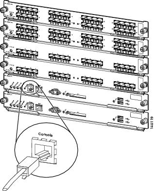
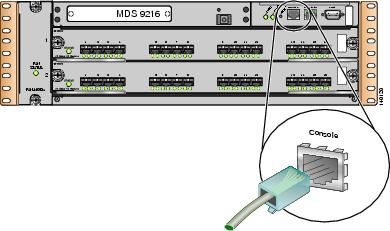
Figure 2-4 Console Connection on an MDS 9500 Series Switch
Figure 2-5 Console Connection on an MDS 9200 Series Switch
Step 3
Step 4
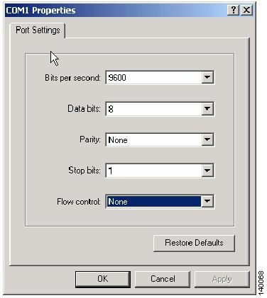
Figure 2-6 HyperTerm Terminal Settings
Step 5
Step 6
Step 7
Step 8
Step 9
switchboot# config terminalStep 10
switch(boot-config)# admin-password temppasswordswitch(boot-config)# exitStep 11
switch(boot)# load bootflash: m9500-sf1ek9-mz.1.3.4b.binStep 12
switch login: adminPassword:Cisco Storage Area Networking Operating System (SAN-OS) SoftwareTAC support: http://www.cisco.com/tacCopyright (c) 2002-2004, Cisco Systems, Inc. All rights reserved.The copyrights to certain works contained herein are owned byAndiamo Systems, Inc. and/or other third parties and are used anddistributed under license. Some parts of this software are coveredunder the GNU Public License. A copy of the license is availableat http://www.gnu.org/licenses/gpl.html.switch#Step 13
ca-9506# config terminalEnter configuration commands, one per line. End with CNTL/Z.ca-9506(config)# username admin password g05oxStep 14
switch# copy running-config startup-config[########################################] 100%
Installing a License
To install a license key, use either the CLI and or the Fabric Manager.
Using the CLI to Install a License
Step 1
switch# copy scp://user1@172.22.36.10/tmp/FM_Server.lic bootflash:FM_Server.licuser1@172.22.36.10's password:FM_Server.lic 100% |*****************************| 2035 00:00Step 2
switch# show license file FM_Server.liclic.lic:SERVER this_host ANYVENDOR ciscoINCREMENT FM_SERVER_PKG cisco 1.0 permanent uncounted \VENDOR_STRING=MDS HOSTID=VDH=FOX0713037X \NOTICE="<LicFileID>lic_template</LicFileID><LicLineID>0</LicLineID> \<PAK>dummyPak</PAK>" SIGN=D8CF07EA26C2Step 3
ca-9506# show license host-idLicense hostid: VDH=FOX0713037XStep 4
switch# install license bootflash:FM_Server.licInstalling license ..doneStep 5
switch# show licenselic.lic:SERVER this_host ANYVENDOR ciscoINCREMENT FM_SERVER_PKG cisco 1.0 permanent uncounted \VENDOR_STRING=MDS HOSTID=VDH=FOX0713037X \NOTICE="<LicFileID>lic_template</LicFileID><LicLineID>0</LicLineID> \<PAK>dummyPak</PAK>" SIGN=D8CF07EA26C2Step 6
switch# show license usageFeature Insta License Status Expiry Date Commentslled Count-----------------------------------------------------------------FM_SERVER_PKG Yes - In use never -MAINFRAME_PKG No - Unused -ENTERPRISE_PKG Yes - In use never -SAN_EXTN_OVER_IP Yes 2 In use never -SAN_EXTN_OVER_IP_IPS4 No 0 Unused ------------------------------------------------------------------Step 7
ca-9506# show license usage ENTERPRISE_PKGApplication-----------Qos Manager-----------
Using Fabric Manager to Install a License
To install a license, follow these steps:
Step 1
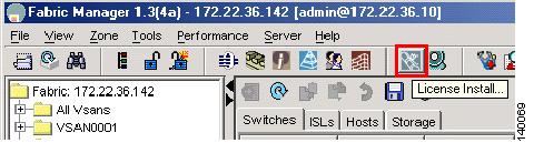
Figure 2-7 License Installation Wizard
Step 2
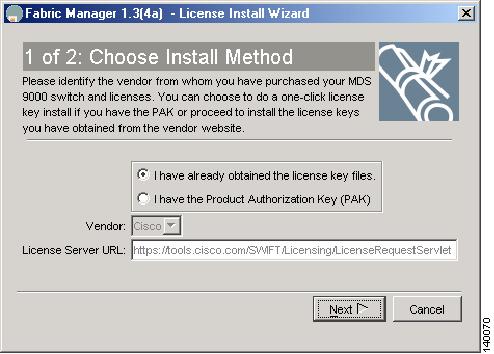
Figure 2-8 License Installation Method
Step 3
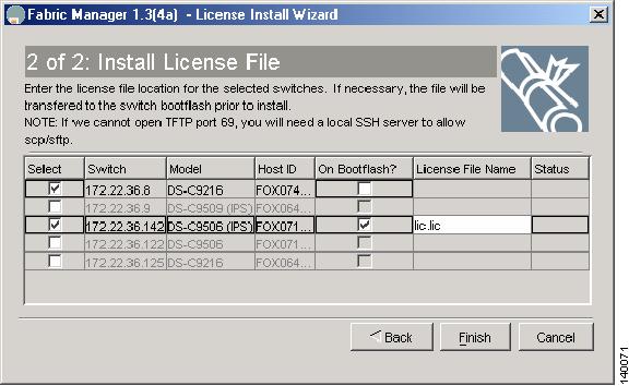
Figure 2-9 License File Location
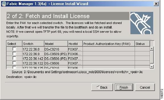
If the license files are not already available, and you only have the PAK numbers, then Fabric Manager can obtain the license files directly from Cisco.com. (See Figure 2-10.)
Figure 2-10 Install License Using PAK
At this point, the license keys can be installed and the licensable feature can be used.
Copying Core Files from the MDS 9000 Switch
If an MDS 9000 switch process crashes, it may create a core file which you can send to Cisco TAC for further troubleshooting. To copy a core file off of the MDS 9000 switch, follow these steps:
Step 1
switch# show coresModule-num Process-name PID Core-create-time---------- ------------ --- ----------------5 fspf 1524 Jul 15 03:11Step 2
"core://<module-number>/<process-id>"switch# copy core://5/1524 ftp://172.22.36.10/tmp/fspfcoreYou can now send the file to Cisco TAC according to the directions you receive from a TAC engineer.
Configuring an NTP Server
Network Time Protocol (NTP) is a protocol used by devices to synchronize their internal clocks with other devices. The Cisco MDS 9000 switch can only be used as an NTP client and can talk to other NTP systems which are considered to have a higher stratum (or authority). NTP is hierarchical in nature such that the lower stratum numbers are closer to the source of the time authority. Devices that are at the same stratum can be configured as peers so that they can work together to determine the correct ime by making minute adjustments. Normally, the MDS 9000 switches are configured as peers, while a router or other dedicated machine is used as an NTP server.
Note
clock timezone EST -5.0
clock summer-time EDT 1 Sunday Apr 02:00 5 Sunday Oct 02:00 60The following example uses these IP addresses:
Switch #1 IP Address: 172.22.36.142
Switch #2 IP Address: 172.22.36.9
NTP Server: 171.69.16.26
To configure NTP for switch1, follow these steps:
Step 1
switch1# conf tEnter configuration commands, one per line. End with CNTL/Z.switch1(config)# ntp server 171.69.16.26Step 2
switch1(config)# ntp peer 172.22.36.9switch1(config)# endAt this point, NTP is configured and the switch will slowly adjust to the new time.
Step 3
switch1# show ntp peers--------------------------------------------------Peer IP Address Serv/Peer--------------------------------------------------171.69.16.26 Server172.22.36.9 Peer
Restoring a Fixed Switch Configuration
This procedure covers the process of backing up and restoring a switch configuration for one of the Cisco MDS 9000 Family switches that have a fixed configuration. These include the Cisco MDS 9216 and 9100 series fabric switches.
This procedure leverages the following resources:
•
•
•
Note
To restore a fixed switch configuration, follow these steps:
Step 1
switch1# copy running-config startup-config[########################################] 100%Step 2
switch1# copy startup-config scp://user@host1/switch1.configuser@switch1's password:sysmgr_system.cfg 100% |*****************************| 10938 00:00switch1#Step 3
switch1# show flogi database---------------------------------------------------------------------------INTERFACE VSAN FCID PORT NAME NODE NAME---------------------------------------------------------------------------fc1/8 600 0x7c0007 50:05:07:63:00:ce:a2:27 50:05:07:63:00:c0:a2:27fc1/13 1001 0xef0001 50:06:0e:80:03:4e:95:13 50:06:0e:80:03:4e:95:13fc1/15 600 0x7c0004 50:06:0b:00:00:13:37:ae 50:06:0b:00:00:13:37:af
Note
Step 4
switch2# write eraseWarning: This command will erase the startup-configuration.Do you wish to proceed anyway? (y/n) [n] yStep 5
switch2# reloadThis command will reboot the system. (y/n)? [n] yWhen the switch comes up in its factory default mode and prompts for the Basic System Configuration Dialog, skip it because all the configuration options are contained in the startup configuration file of the old switch.
Step 6
switch2# config terminalEnter configuration commands, one per line. End with CNTL/Z.switch2(config)# int mgmt 0switch2(config-if)# ip address 172.22.36.8 255.255.254.0switch2(config-if)# no shutStep 7
switch2# show wwn switchSwitch WWN is 20:00:00:0d:ec:02:1d:40Step 8
a.
$ cp switch1.config switch1.config.orig$ vi switch1.configThe user accounts are all grouped together and begin with snmp-server user:
snmp-server user admin network-admin auth md5 0x46694cac2585d39d3bc00c8a4c7d48a6localizedkeysnmp-server user guestadmin network-admin auth md5 0xcae40d254218747bc57ee1df34826b51 localizedkeyb.
zone name Z_1 vsan 9member interface fc1/9 swwn 20:00:00:0d:ec:02:1d:40c.
Step 9
switch2# copy scp://user@host1/switch1.config running-configuser@host1's password:switch1.config 100% |*****************************| 10938 00:00Step 10
switch1# copy running-config startup-config[########################################] 100%:Step 11
a.
b.
c.
Step 12
Step 13
Step 14
Step 15
Preparing to Call Cisco TAC
At some point, the administrator may need to contact the Cisco TAC or their OSM for some additional assistance. This section outlines the steps that the administrator should perform prior to contacting their next level of support, as this will reduce the amount of time needed to resolve the issue.
Step 1
Step 2
a.
b.
tac-pac bootflash://showtech.switch1.
The tac-pac command redirects the output of a show tech-support details command to a file that you can then gzip. If no filename is specified, the file created is volatile:show_tech_out.gz. Copy the file off the MDS 9000 switch using the procedure described in Copying Files to or from the MDS 9000 Switch.c.
Step 3
a.
b.
Step 4
a.
b.
c.
d.
e.
f.
g.
h.
i.
j.
–
–
–
–
Implementing Syslog
The syslog message server allows Cisco MDS 9000 switches to send a copy of the message log to a host for more permanent storage. Saving the logs in this way can be useful if the logs need to be examined over a long period of time or when the MDS 9000 switch is not accessible.
This example demonstrates how to configure a Cisco MDS 9000 switch to use the syslog facility on a Solaris platform. Although a Solaris host is being used, the syslog configuration on all UNIX and Linux systems is very similar.
Syslog uses the concept of a facility to determine how a message should be handled on the syslog server (the Solaris system in this example), and the message severity. Therefore, different message severities can be handled differently by the syslog server. They could be logged to different files or sent via e-mail to a particular user. Specifying a severity determines that all messages of that level and greater severity (lower number) will be acted upon.
Tip
Syslog Client: switch1
Syslog Server: 172.22.36.211 (Solaris)
Syslog facility: local1
Syslog severity: notifications (level 5, the default)
File to log MDS messages to: /var/adm/MDS_logs
To configure a Cisco MDS 9000 switch to use the syslog facility on a Solaris platform, follow these steps:
Step 1
switch1# config terminalEnter configuration commands, one per line. End with CNTL/Z.switch1(config)# logging server 172.22.36.211 6 facility local1Step 2
switch1# show logging serverLogging server: enabled{172.22.36.211}server severity: notificationsserver facility: local1Step 3
a.
#Below is for the MDS 9000 logginglocal1.notice /var/adm/MDS_logsb.
#touch /var/adm/MDS_logsc.
# /etc/init.d/syslog stop# /etc/init.d/syslog startsyslog service starting.d.
# ps -ef |grep syslogdroot 23508 1 0 11:01:41 ? 0:00 /usr/sbin/syslogdStep 4
# tail -f /var/adm/MDS_logsSep 17 11:07:41 [172.22.36.142.2.2] : 2004 Sep 17 11:17:29 pacific: %PORT-5-IF_DOWN_INITIALIZING: %$VSAN 1%$ Interface fc1/2 is down (Initializing)Sep 17 11:07:49 [172.22.36.142.2.2] : 2004 Sep 17 11:17:36 pacific: %PORT-5-IF_UP: %$VSAN 1%$ Interface fc1/2 is up in mode TESep 17 11:07:51 [172.22.36.142.2.2] : 2004 Sep 17 11:17:39 pacific: %VSHD-5-VSHD_SYSLOG_CONFIG_I: Configuring console from pts/0 (dhcp-171-71-49-125.cisco.com)