Feedback
Table Of Contents
TCP Tuning: Latency and Available Bandwidth
FCIP
FCIP (Fibre Channel over IP) is an IETF standards based protocol for connecting Fibre Channel SANs over IP based networks. FCIP encapsulates the FCP frames in a TCP/IP packet which is then sent across an IP network. FCIP can interconnect geographically dispersed SANs using the IP backbone network. In short, FCIP creates an FC tunnel over an existing IP network. The MDS 9200 and MDS 9500 series switches support FCIP, using the IPS-8, IPS-4 and the 14+2 blades.
This chapter explains how to enable and configure FCIP and includes the following sections:
Enabling FCIP
You must enable FCIP before attempting to configure it on the switch.
Warning
If you do not run the FCIP enable command, further FCIP configuration is not possible. This command enables additional FCIP configuration options in the CLI.
MDS1# conf tEnter configuration commands, one per line. End with CNTL/Z.MDS1(config)# FCIP enableMDS1(config)#^ZMDS1#Configuring FCIP
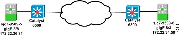
The recipe below shows the configuration of FCIP on the Cisco MDS 9000 switch. Figure 9-1 shows the topology.
Figure 9-1 FCIP Topology
The topology consists of two MDS 9509 switches, each with one IPS-8 blade. The Gigabit Ethernet port 8/8 on the switch sjc7-9509-5 is connected to a Catalyst 6509. The interface has an IP address of 172.22.36.81, with a subnet mask of 255.255.254.0, and the gateway address of 172.22.36.1.Another switch, sjc7-9509-6, has the Gigabit Ethernet port 8/3 also connected to a Catalyst 6509. This interface has an IP address of172.22.34.58, with a subnet of 255.255.254.0, and the gateway address of 172.22.34.1. In the recipe, the FCIP tunnel is established between the switch sjc7-9509-5 (GE 8/8) and sjc7-9509-6 (GE 8/3).
Warning
To make FCIP operational between the switches, follow these steps:
Step 1
sjc7-9509-6# conf tEnter configuration commands, one per line. End with CNTL/Z.sjc7-9509-6(config)# interface gigabitethernet 8/3sjc7-9509-6(config-if)# ip address 172.22.34.58 255.255.254.0sjc7-9509-6(config-if)# no shutsjc7-9509-6(config-if)# ^Zsjc7-9509-5#Step 2
In the preceding step, the Gigabit Ethernet ports are in two different subnets. As a result, explicit routes are required to allow the two switches to communicate with each other.
Note
Step 3
sjc7-9509-5# conf tEnter configuration commands, one per line. End with CNTL/Z.sjc7-9509-5(config)# ip route 172.22.34.58 255.255.255.255 172.22.36.1 interface gigabitethernet 8/8sjc7-9509-5(config)# ^Zsjc7-9509-5#In this configuration, you use the gateway 172.22.36.1 and interface GE 8/8 on switch sjc7-9509-5 to reach 172.22.34.58.
Step 4
sjc7-9509-6# conf tEnter configuration commands, one per line. End with CNTL/Z.sjc7-9509-6(config)# ip route 172.22.36.81 255.255.255.255 172.22.34.1 interface gigabitethernet 8/3sjc7-9509-6(config-if)# ^Zsjc7-9509-6#In this configuration, you use the gateway 172.22.34.1 and interface GE 8/3 on switch sjc7-9509-6 to reach 172.22.36.81.
Step 5
a.
b.
sjc7-9509-5# ping 172.22.34.58PING 172.22.34.58 (172.22.34.58) 56(84) bytes of data.64 bytes from 172.22.34.58: icmp_seq=1 ttl=254 time=1.04 ms64 bytes from 172.22.34.58: icmp_seq=2 ttl=254 time=0.624 ms64 bytes from 172.22.34.58: icmp_seq=3 ttl=254 time=0.678 ms64 bytes from 172.22.34.58: icmp_seq=4 ttl=254 time=0.580 ms--- 172.22.34.58 ping statistics ---4 packets transmitted, 4 received, 0% packet loss, time 3008msrtt min/avg/max/mdev = 0.580/0.732/1.046/0.184 mssjc7-9509-5#sjc7-9509-6# ping 172.22.36.81PING 172.22.36.81 (172.22.36.81): 56 data bytes64 bytes from 172.22.36.81: icmp_seq=0 ttl=254 time=0.7 ms64 bytes from 172.22.36.81: icmp_seq=1 ttl=254 time=0.6 ms64 bytes from 172.22.36.81: icmp_seq=2 ttl=254 time=0.5 ms64 bytes from 172.22.36.81: icmp_seq=3 ttl=254 time=0.6 ms--- 172.22.36.81 ping statistics ---4 packets transmitted, 4 packets received, 0% packet lossround-trip min/avg/max = 0.5/0.6/0.7 mssjc7-9509-6#
Note
Step 6
sjc7-9509-5# ips measure-rtt 172.22.34.58 interface gigabitethernet 8/8Round trip time is 691 micro seconds (0.69 milli seconds)sjc7-9509-5#sjc7-9509-6# ips measure-rtt 172.22.36.81 interface gigabitethernet 8/3Round trip time is 743 micro seconds (0.74 milli seconds)sjc7-9509-6#Step 7
The profile defines the characteristics for the FCIP tunnel that you set up. The measured round-trip time is needed during the profile configuration. Round the value to the nearest whole number. In this case, the 690 microseconds is rounded to 1 millisecond. The IP address in the configuration that follows is the IP address assigned to the Gigabit Ethernet interface on the switch.
Tip
sjc7-9509-5# conf tEnter configuration commands, one per line. End with CNTL/Z.sjc7-9509-5(config)# fcip profile 10sjc7-9509-5(config-profile)# ip address 172.22.36.81sjc7-9509-5(config-profile)# tcp max-bandwidth-mbps 1000 min-available-bandwidth-mbps 200 round-trip-time-ms 1sjc7-9509-5(config-if)# ^Zsjc7-9509-5#sjc7-9509-6# conf tEnter configuration commands, one per line. End with CNTL/Z.sjc7-9509-6(config)# fcip profile 10sjc7-9509-6(config-profile)# ip address 172.22.34.58sjc7-9509-6(config-profile)# tcp max-bandwidth-mbps 1000 min-available-bandwidth-mbps 200 round-trip-time-ms 1sjc7-9509-6(config-if)# ^Zsjc7-9509-6#Step 8
In the FCIP interface configuration that follows, the profile used and the peer information (remote Gigabit Ethernet IP address) are specified. Compression and write acceleration can also be configured.
sjc7-9509-5# conf tEnter configuration commands, one per line. End with CNTL/Z.sjc7-9509-5(config)# interface fcip 1sjc7-9509-5(config-if)# use-profile 10sjc7-9509-5(config-if)# peer-info ipaddr 172.22.34.58sjc7-9509-5(config-if)# no shutsjc7-9509-5(config-if)# ^Zsjc7-9509-5#sjc7-9509-6# conf tEnter configuration commands, one per line. End with CNTL/Z.sjc7-9509-6(config)# interface fcip 1sjc7-9509-6(config-if)# use-profile 10sjc7-9509-6(config-if)# peer-info ipaddr 172.22.36.81sjc7-9509-6(config-if)# no shutsjc7-9509-6(config-if)# ^Zsjc7-9509-6#The FCIP tunnel should be up and running now.
Step 9
sjc7-9509-5# show interface fcip 1 brief-------------------------------------------------------------------------------Interface Vsan Admin Admin Status Oper Profile Eth Int Port-channelMode Trunk ModeMode-------------------------------------------------------------------------------fcip1 1 auto on trunking TE 10 GigabitEthernet8/8 --sjc7-9509-5#sjc7-9509-6# show interface fcip 1 brief-------------------------------------------------------------------------------Interface Vsan Admin Admin Status Oper Profile Eth Int Port-channelMode Trunk ModeMode-------------------------------------------------------------------------------fcip1 1 auto on trunking TE 10 GigabitEthernet8/3 --sjc7-9509-6#Tuning FCIP
Implementing an FCIP tunnel is more than just creating the FCIP link and modifying the VSAN allowed list. To achieve the greatest efficiency from the link, some parameters that are specific to the underlying connection may need to be tuned. Therefore, if the FCIP link is running over a slow, 1 MB connection, the FCIP link should be tuned differently than one running over a low-latency, 1 GB connection. This section provides insight into what parameters can be used and how to use them for achieving increased efficiency and utilization from the FCIP connection.
Note
Figure 9-2 shows the topology that is used throughout this chapter:
Figure 9-2 FCIP Topology
TCP Tuning: Latency and Available Bandwidth
The latency of the link is the amount of time that it takes a packet to go from one end of the FCIP link to the other. Latency can be due to many factors, including distance and the number of devices that the packet must traverse. Even the fastest routers and switches incur some amount of latency.
Latency cannot be eliminated; however protocols can be tuned and MDS features such as FCIP Write Acceleration (see FCIP Write Acceleration) can be enabled to eliminate the effects of it. These features can be modified in the FCIP profile.
Available bandwidth is the amount of bandwidth that the FCIP link can use on the network. You need to define a maximum and a minimum value for the FCIP link to use in the FCIP profile.
•
•
Tip
Table 9-1 contains some common WAN links and their speeds. These circuits are most often used as the underlying network for an FCIP link. For example, the underlying network may be a OC3, but you may only be able to use 100 MB of that link.
Tip
Table 9-1 Common WAN Circuit Speeds
T1
1.544 Mbps
T3
43.232 Mbps
OC-3
155 Mbps
OC-12
622 Mbps
OC-48
2.5 Gbps
OC-192
9.6 Gbps
To specify the minimum and maximum available bandwidth and the network latency, perform the following procedure. For this example, we assume that the LAN/WAN links are a dedicated Gigabit Ethernet link.
Step 1
sjc7-9509-5# ips measure-rtt 172.22.34.58 interface gigabitethernet 8/8Round trip time is 5691 micro seconds (5.69 milli seconds)sjc7-9509-6# ips measure-rtt 172.22.36.81 interface gigabitethernet 8/3Round trip time is 5743 micro seconds (5.74 milli seconds)Step 2
sjc7-9509-5# conf tEnter configuration commands, one per line. End with CNTL/Z.sjc7-9509-5(config)# fcip profile 2sjc7-9509-5(config-profile)# tcp max-bandwidth-mbps 1000 min-available-bandwidth-mbps 1000 round-trip-time-us 5691sjc7-9509-6# conf tEnter configuration commands, one per line. End with CNTL/Z.sjc7-9509-6(config)# fcip profile 2sjc7-9509-6(config-profile)# tcp max-bandwidth-mbps 1000 min-available-bandwidth-mbps 1000 round-trip-time-us 5743
FCIP Write Acceleration
To alleviate the effects of latency, the IPS-8 and IPS-4 blades support software compression. The configuration is shown below.
Note
Step 1
sjc7-9509-5# conf tEnter configuration commands, one per line. End with CNTL/Z.sjc7-9509-5(config)# interface fcip 1sjc7-9509-5(config)# write-acceleratorsjc7-9509-5(config)# ip-compression mode high-throughputsjc7-9509-5(config)# ^Zsjc7-9509-5#Step 2
sjc7-9509-6# conf tEnter configuration commands, one per line. End with CNTL/Z.sjc7-9509-6(config)# interface fcip 1sjc7-9509-6(config)# write-acceleratorsjc7-9509-6(config)# ip-compression mode high-throughputsjc7-9509-6(config)# ^Zsjc7-9509-6#
FCIP Compression
FCIP based compression should be enabled when the bandwidth requirements of the application (such as SRDF, TrueCopy, or PPRC) exceed the bandwidth that the LAN or WAN link can provide.
For SAN-OS versions prior to 2.0, software compression was available on the IP Services Module using two compression modes, a high compression ratio, and high throughput. For environments where the bandwidth speed of the WAN is relatively low (such as T3/DS 3, 45 Mbps and lower speeds), the high compression ratio option should be enabled. For WAN links up to OC-3, 155 Mbps, the high throughput option should be enabled.
In SAN-OS version 2.0, three new modes of compression were introduced, along with hardware based compression using the 14+2 module. These modules are summarized in Figure 9-3.
Note
Figure 9-3 Approximate Application Throughput with MDS 2.0 Compression