Solution Implementation
Overview
Cisco customers have asked Cisco to provide insight into how Cisco products can be used to address PCI DSS 2.0 requirements. To fully accomplish this goal, Cisco hired an auditor and went through the same process as retailers. To audit Cisco products for the capability to address compliance, they had to be installed and configured within a representative design.
This chapter demonstrates how the Cisco PCI Solution for Retail was installed and configured to address the specifications of PCI 2.0. Cisco partnered with RSA, HyTrust, EMC, VCE, and Verizon Business to create a comprehensive design that reflected the framework and architectural principles discussed in earlier chapters.
The Cisco PCI Solution for Retail was validated in the Cisco Retail Lab in San Jose, California. The stores, data center, WAN, and Internet edge network infrastructures were built using Cisco best practice design guides, as represented by the Connected Retail Reference Architecture (http://www.cisco.com/go/designzone). The individual components were installed and configured to adhere to PCI 2.0 specifications. Verizon Business then conducted an assessment of the design and advised on remediation for specific configurations of individual components. After the remediation was complete, Verizon Business provided a detailed reference architecture report (see Appendix B, "Verizon Business Reference Architecture Report—Cisco PCI Solution for Retail.")

Tip ![]() An architecture is a strategic structure for the consistent design, construction, and operation of systems to achieve a desired set of outcomes.
An architecture is a strategic structure for the consistent design, construction, and operation of systems to achieve a desired set of outcomes.
A design is a tactical implementation of an architectural strategy, using specific configurations of products to satisfy business requirements.
Chapter 3, "Solution Architecture," describes the enterprise architecture with regards to compliance. This chapter demonstrates a design or, in other words, a specific implementation of components to achieve these principles. Various designs can result from the solution architecture. The design that was implemented is not intended to represent the only way that Cisco and partner products can be installed to address PCI. It is intended to provide an example showing how and what was used to achieve the principles described in Chapter 3, "Solution Architecture."
Although every company has specific considerations that vary from this implementation, these designs and the configurations of the components in "Detailed Full Running Configurations," provide an instructive example of what is needed to secure credit card data. Each component selected was audited for its capabilities, and that assessment is covered in the next chapter.
In each section, the reference architecture is shown with the corresponding design that was implemented and validated within the Cisco PCI laboratories. The full configurations of each individual component are available in "Detailed Full Running Configurations."
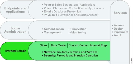
Infrastructure
The infrastructure layer of the solution framework addresses the components such as routers, switches, firewalls, and security components, as shown in Figure 4-1.
Figure 4-1 Infrastructure Layer of the Solution Framework
The following sections describe the designs that were implemented from the reference architecture.
Figure 4-2 shows the retail enterprise-wide reference architecture.
Figure 4-2 Retail Enterprise-Wide Reference Architecture
Referencing the retail enterprise-wide architecture shown in Figure 4-2, the design shown in Figure 4-3 was created in the Cisco Retail Lab.
Figure 4-3 Cisco PCI Solution for Retail Lab Architecture

Note the following:
•![]() Six store designs were selected to represent Cisco and partner products.
Six store designs were selected to represent Cisco and partner products.
•![]() The data center consists of a single aggregation block based on the Data Center 3.0 architecture.
The data center consists of a single aggregation block based on the Data Center 3.0 architecture.
•![]() The Internet edge is representative of both the e-commerce and partner edge for the purposes of validation.
The Internet edge is representative of both the e-commerce and partner edge for the purposes of validation.
The following sections describe this enterprise-wide design in more detail, and demonstrate what was implemented within the lab.
Stores
Multiple store footprints were implemented that address a variety of business objectives. Each store footprint section contains designs that were extracted from the reference architecture. Each design contains the following:
•![]() Reference architecture
Reference architecture
•![]() Store design
Store design
–![]() Logical topology
Logical topology
–![]() Addressing plan
Addressing plan
–![]() Components selected
Components selected
For component compliance functionality, see Chapter 5, "Component Assessment.". For full device configurations, see "Detailed Full Running Configurations."

Note ![]() Each of these store designs includes a variety of components that can be interchangeably used between them, depending on business requirements. For validation purposes, it was not necessary to implement all possible components in each design.
Each of these store designs includes a variety of components that can be interchangeably used between them, depending on business requirements. For validation purposes, it was not necessary to implement all possible components in each design.
Small Store Architecture
The small store network scenario, shown in Figure 4-4, meets the following design requirements:
•![]() Store size averages between 2000-6000 square feet
Store size averages between 2000-6000 square feet
•![]() Fewer than 25 devices requiring network connectivity
Fewer than 25 devices requiring network connectivity
•![]() Single router with firewall/IPS, integrated Ethernet switch, compact switch, and power-over-Ethernet (PoE)
Single router with firewall/IPS, integrated Ethernet switch, compact switch, and power-over-Ethernet (PoE)
•![]() Preference for integrated services within fewer network components because of physical space requirements
Preference for integrated services within fewer network components because of physical space requirements
•![]() Wireless connectivity
Wireless connectivity
Figure 4-4 Small Store Architecture

The small store reference architecture is a powerful platform for running an enterprise retail business that requires simplicity and a compact form factor. This combination appeals to many retail formats that can include the following:
•![]() Small store—Specialty shops, discount retailers
Small store—Specialty shops, discount retailers
•![]() Mini stores—Fuel stations, mall outlet
Mini stores—Fuel stations, mall outlet
•![]() Convenience stores—Pop-up stores, mall kiosks
Convenience stores—Pop-up stores, mall kiosks
•![]() Managed service provider store—WAN access controlled by service provider
Managed service provider store—WAN access controlled by service provider
This network architecture is widely used and consolidates many services into fewer infrastructure components. The small store also supports a variety of retail business application models because an integrated Ethernet switch supports high-speed LAN services. In addition, an integrated content engine supports centralized application optimization requirements such as Web Cache Communications Protocol (WCCP)-based caching, pre-positioning of data, local media streaming, and other application velocity services.
Advantages include the following:
•![]() Lower cost per store
Lower cost per store
•![]() Fewer parts to spare
Fewer parts to spare
•![]() Fewer software images to maintain
Fewer software images to maintain
•![]() Lower equipment maintenance costs
Lower equipment maintenance costs
Limitations include the following:
•![]() Decreased levels of network resilience
Decreased levels of network resilience
•![]() Greater potential downtime because of single points of failure
Greater potential downtime because of single points of failure
Small Store—Small Design
Figure 4-5 shows the small store network design.
Figure 4-5 Small Store Network Design
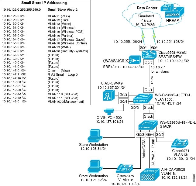
Components Selected
•![]() Cisco 2921 Integrated Services Router (ISR)
Cisco 2921 Integrated Services Router (ISR)
•![]() Cisco Catalyst 2960S 48-port PoE Switch
Cisco Catalyst 2960S 48-port PoE Switch
•![]() Cisco Aironet 3502i Access Points
Cisco Aironet 3502i Access Points
•![]() Cisco Video Surveillance 4500 Series IP Cameras
Cisco Video Surveillance 4500 Series IP Cameras
•![]() Cisco Physical Access Gateway
Cisco Physical Access Gateway
Small Store—Mini Design
The mini store represents an alternate design for the small store architecture, using different components.
Figure 4-6 shows the mini store network design.
Figure 4-6 Mini Store Network Design

Components Selected
•![]() Cisco 1941 Integrated Services Router (ISR)
Cisco 1941 Integrated Services Router (ISR)
•![]() Cisco Catalyst 2960 Switch
Cisco Catalyst 2960 Switch
•![]() Cisco Aironet 3502e Access Point
Cisco Aironet 3502e Access Point
Small Store—Convenience Design
The convenience store represents an alternate design for the small store architecture. Figure 4-7 shows the convenience store network design.
Figure 4-7 Convenience Store Network Design
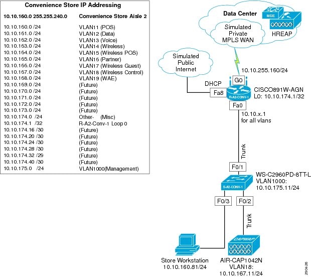
Components Selected
•![]() Cisco 891 Series Integrated Services Router (ISR)
Cisco 891 Series Integrated Services Router (ISR)
•![]() Cisco Catalyst 2960 Series Switch
Cisco Catalyst 2960 Series Switch
•![]() Cisco Aironet 1042N Access Point
Cisco Aironet 1042N Access Point
Small Store—Managed Service Provider Design
The managed service provider store represents an alternate design for the small store architecture. Figure 4-8 shows the managed service provider network design.
Figure 4-8 Managed Service Provider Network Design
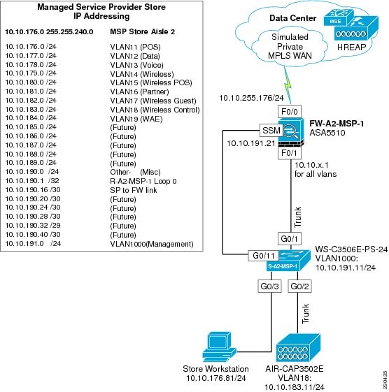
Components Selected
•![]() Cisco ASA 5510 Firewall with SSM-10
Cisco ASA 5510 Firewall with SSM-10
•![]() Cisco Catalyst 3560E Switch
Cisco Catalyst 3560E Switch
•![]() Cisco Aironet 3502e Access Points
Cisco Aironet 3502e Access Points
Medium Store Architecture
The medium store network scenario, shown in Figure 4-9, meets the following design requirements:
•![]() Store size averages between 6,000-18,000 square feet
Store size averages between 6,000-18,000 square feet
•![]() The physical size of the store is smaller than a large store, so a distribution layer of network switches is not required
The physical size of the store is smaller than a large store, so a distribution layer of network switches is not required
•![]() Number of devices connecting to the network averages 25-100 devices
Number of devices connecting to the network averages 25-100 devices
•![]() Redundant LAN and WAN infrastructures with firewall/IPS
Redundant LAN and WAN infrastructures with firewall/IPS
•![]() Wireless connectivity
Wireless connectivity
Figure 4-9 Medium Store Architecture

The medium retail store reference architecture is designed for enterprise retail businesses that require network resilience and increased levels of application availability over the small store architecture and its single-threaded, simple approach. As more mission-critical applications and services converge onto the IP infrastructure, network uptime and application availability are more important. The dual-router and dual-LAN switch design of the medium store supports these requirements. Each of the Cisco ISR routers can run Cisco IOS Software security services and other store communication services simultaneously. Each of the Cisco ISR routers is connected to a dedicated WAN connection. Hot Standby Routing Protocol (HSRP) is used to ensure network resilience in the event that the network connection fails.
The access layer of the network offers enhanced levels of flexibility and more access ports compared to the small store. Up to 12 wireless access points can be installed in the store, supported by the Cisco Wireless Control System (WCS) controller as tested and without adding more controllers. The distributed Cisco Catalyst switches can support a combination of larger physical buildings or a larger number of endpoints than the small store.
Advantages include the following:
•![]() More adaptive access layer with support for a greater number of endpoints and more diverse building requirements (multiple floors, sub-areas, and so on)
More adaptive access layer with support for a greater number of endpoints and more diverse building requirements (multiple floors, sub-areas, and so on)
•![]() Improved network resilience through parallel device design
Improved network resilience through parallel device design
•![]() Improved network and application availability through parallel paths
Improved network and application availability through parallel paths
Limitations include the following:
•![]() No distribution layer between core layer (the ISR) and the access layer switches
No distribution layer between core layer (the ISR) and the access layer switches
•![]() Single WCS Controller decreases in-store resilience of the wireless network; the recommendation is to have store APs fallback to the central WCS controller if the local WCS controller fails, or to install dual-local WCS controllers.
Single WCS Controller decreases in-store resilience of the wireless network; the recommendation is to have store APs fallback to the central WCS controller if the local WCS controller fails, or to install dual-local WCS controllers.
Medium Store—Design
Figure 4-10 shows the medium store network design.
Figure 4-10 Medium Store Network Design
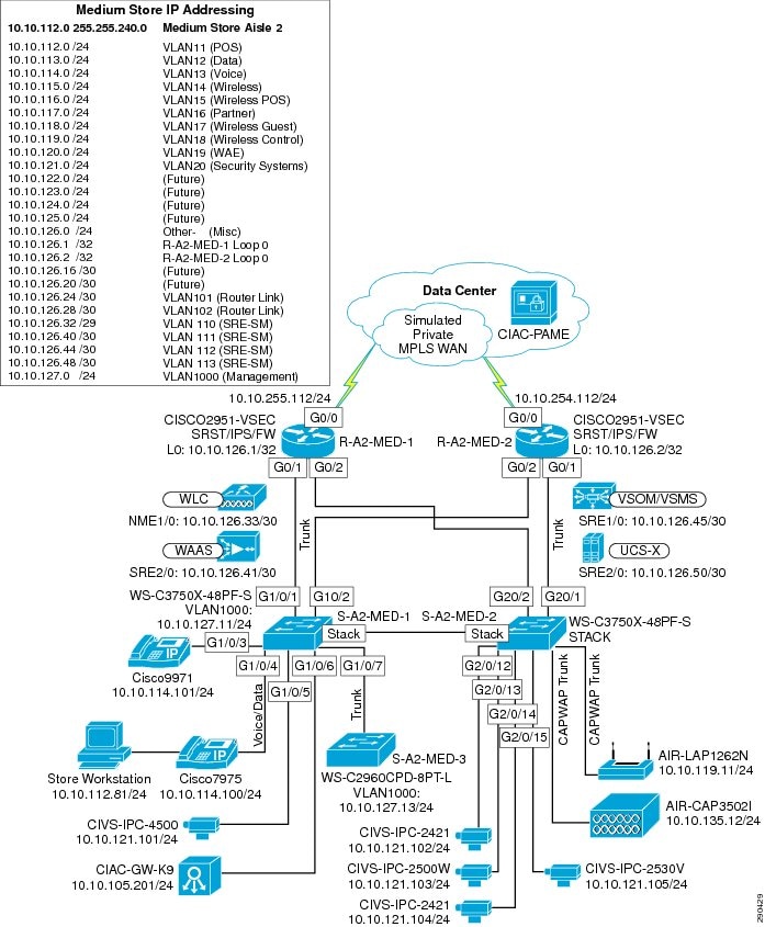
Components Selected
•![]() Cisco 2951 Integrated Services Router (ISR)
Cisco 2951 Integrated Services Router (ISR)
•![]() Cisco Catalyst 3750X 48-port PoE Switch
Cisco Catalyst 3750X 48-port PoE Switch
•![]() Cisco Catalyst 2960 Compact Switch
Cisco Catalyst 2960 Compact Switch
•![]() Cisco Aironet 3502e and 1262N Access Points
Cisco Aironet 3502e and 1262N Access Points
•![]() Cisco Video Surveillance 2421 IP Dome Camera
Cisco Video Surveillance 2421 IP Dome Camera
•![]() Cisco Video Surveillance 2500 Series IP Camera
Cisco Video Surveillance 2500 Series IP Camera
•![]() Cisco Operations Manager v4.1
Cisco Operations Manager v4.1
•![]() Cisco Physical Access Gateway
Cisco Physical Access Gateway
Large Store Architecture
The large store network scenario, shown in Figure 4-11, meets the following design requirements:
•![]() Store size averages between 15,000-150,000 square feet
Store size averages between 15,000-150,000 square feet
•![]() More than 100 devices per store requiring network connectivity
More than 100 devices per store requiring network connectivity
•![]() Multiple routers with firewall/IPS for primary and backup network requirements
Multiple routers with firewall/IPS for primary and backup network requirements
•![]() Preference for a combination of network services distributed within the store to meet resilience and application availability requirements
Preference for a combination of network services distributed within the store to meet resilience and application availability requirements
•![]() Tiered network architecture within the store; distribution layer switches are employed between the central network services core and the access layer connecting to the network endpoints (POS, wireless APs, servers)
Tiered network architecture within the store; distribution layer switches are employed between the central network services core and the access layer connecting to the network endpoints (POS, wireless APs, servers)
Figure 4-11 Large Store Architecture

The large retail store reference architecture takes some of the elements of Cisco campus network architecture recommendations and adapts them to a large retail store environment. Network traffic can be better segmented (logically and physically) to meet business requirements. The distribution layer of the large store architecture can greatly improve LAN performance while offering enhanced physical media connections (that is, fiber and copper for connection to remote access layer switches and wireless access points). A larger number of endpoints can be added to the network to meet business requirements. This type of architecture is widely used by large format retailers globally. Dual routers and distribution layer media flexibility greatly improve network serviceability because the network is highly available and scales to support the large retail store requirements. Routine maintenance and upgrades can be scheduled and performed more frequently or during normal business hours because of parallel path design.
Advantages include the following:
•![]() Highest network resilience based on highly available design
Highest network resilience based on highly available design
•![]() Port density and fiber density for large retail locations
Port density and fiber density for large retail locations
•![]() Increase segmentation of traffic
Increase segmentation of traffic
•![]() Scalable to accommodate shifting requirements in large retail stores
Scalable to accommodate shifting requirements in large retail stores
Limitations include the following:
•![]() Higher cost because of network resilience based on highly available design
Higher cost because of network resilience based on highly available design
•![]() These retail store network designs are capable of helping a retailer achieve PCI compliance, and also serve as the scalable platform for new services and applications
These retail store network designs are capable of helping a retailer achieve PCI compliance, and also serve as the scalable platform for new services and applications
Large Store Design
Figure 4-12 shows the large store network design.
Figure 4-12 Large Store Network Design
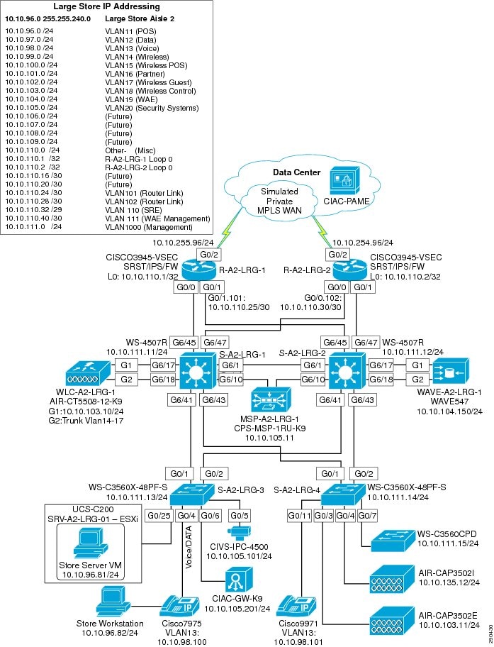
Components Selected
•![]() Cisco 3945 Integrated Services Router (ISR)
Cisco 3945 Integrated Services Router (ISR)
•![]() Cisco Catalyst 3560X and 4500 switches
Cisco Catalyst 3560X and 4500 switches
•![]() Cisco Aironet 3502e and 3502i Access Points
Cisco Aironet 3502e and 3502i Access Points
•![]() Cisco 5508 Wireless Controller
Cisco 5508 Wireless Controller
•![]() Cisco 4500 Video Surveillance Camera
Cisco 4500 Video Surveillance Camera
•![]() Cisco Physical Access Gateway
Cisco Physical Access Gateway
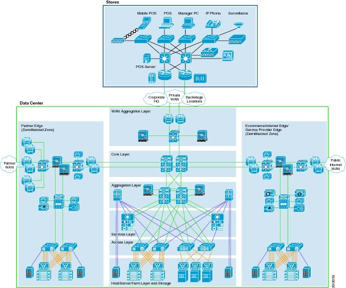
Data Center
The data center is where centralized data processing, data storage, and data communications take place (see Figure 4-13). The data center is also the place where management systems are deployed. The data center provides centralized control from an administrative perspective because it is typically where the tools that are used to monitor and enforce compliance are deployed.
Figure 4-13 Data Center Architecture
Design considerations are as follows:
•![]() Centralized solution management supports all aspects of network, security, and systems management; and supports remote access from anywhere on the network.
Centralized solution management supports all aspects of network, security, and systems management; and supports remote access from anywhere on the network.
•![]() Standardized equipment and software images, deployed in a modular, layered approach, simplify configuration management and increase the systems availability.
Standardized equipment and software images, deployed in a modular, layered approach, simplify configuration management and increase the systems availability.
•![]() The highly available data center design permits highly resilient access from stores to core data and storage services.
The highly available data center design permits highly resilient access from stores to core data and storage services.
•![]() WAN aggregation alternatives allow flexible selection of service provider network offerings.
WAN aggregation alternatives allow flexible selection of service provider network offerings.
•![]() The service aggregation design allows for a modular approach to adding new access layers and managing shared network services (for example, firewall, IPS, application networking, wireless management)
The service aggregation design allows for a modular approach to adding new access layers and managing shared network services (for example, firewall, IPS, application networking, wireless management)
•![]() Firewall, IPS, and application networking services are available at the service and aggregation layers of the data center.
Firewall, IPS, and application networking services are available at the service and aggregation layers of the data center.
•![]() Scalability to accommodate shifting requirements in data center compute and storage requirements.
Scalability to accommodate shifting requirements in data center compute and storage requirements.
•![]() WAN access speeds are typically the limiting factor between the store network systems and the WAN aggregation layer.
WAN access speeds are typically the limiting factor between the store network systems and the WAN aggregation layer.
•![]() It is typical for retailers to over-subscribe the WAN circuits between the stores and the WAN edge aggregation router. Over-subscription can cause inconsistent results and packet loss of payment card information in the event that more traffic enters the WAN circuit simultaneously.
It is typical for retailers to over-subscribe the WAN circuits between the stores and the WAN edge aggregation router. Over-subscription can cause inconsistent results and packet loss of payment card information in the event that more traffic enters the WAN circuit simultaneously.
•![]() Backup network connections from store networks to the data center are recommended when payment card information is transported via the WAN.
Backup network connections from store networks to the data center are recommended when payment card information is transported via the WAN.
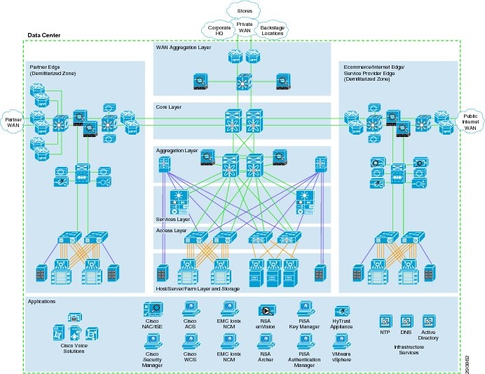
Figure 4-14 shows the data center design.
Figure 4-14 Data Center Design
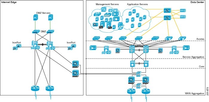
Data centers can house many types of functions and the term itself can encompass narrow and broad aspects. For the purposes of this guide, data centers include the following functions:
•![]() WAN aggregation layer—Aggregates the store and backstage WAN connections to the core
WAN aggregation layer—Aggregates the store and backstage WAN connections to the core
•![]() Core layer—Highly available, high-speed area that is the central point of connectivity to all data center areas
Core layer—Highly available, high-speed area that is the central point of connectivity to all data center areas
•![]() Aggregation block—Aggregates the services of one area and connects that area to the core, including Vblock1 design
Aggregation block—Aggregates the services of one area and connects that area to the core, including Vblock1 design
•![]() Internet edge—Secure connectivity to the Internet
Internet edge—Secure connectivity to the Internet
WAN Aggregation Layer Design
Figure 4-15 shows the WAN aggregation layer design.
Figure 4-15 WAN Aggregation Layer Design
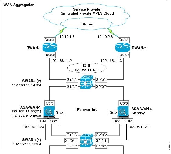
Components Selected
•![]() Cisco ASR 1002-Fixed Router
Cisco ASR 1002-Fixed Router
•![]() Cisco ASA 5540 Adaptive Security Appliance
Cisco ASA 5540 Adaptive Security Appliance
•![]() Cisco Catalyst 3750X Switch
Cisco Catalyst 3750X Switch
Core Layer Design
Figure 4-16 shows the core layer design.
Figure 4-16 Core Layer Design

Components Selected
•![]() Cisco Catalyst 6500-E Switch
Cisco Catalyst 6500-E Switch
Aggregation Block Design
Figure 4-17 shows the aggregation block design.
Figure 4-17 Aggregation Block Design
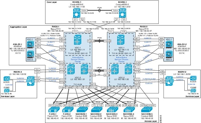
Components Selected
•![]() Cisco ASA 5585-X Adaptive Security Appliance
Cisco ASA 5585-X Adaptive Security Appliance
•![]() Cisco Nexus 7010 Switch
Cisco Nexus 7010 Switch
•![]() Cisco Catalyst 6500-E Switch
Cisco Catalyst 6500-E Switch
–![]() Cisco ACE 20
Cisco ACE 20
–![]() Cisco IDSM-2
Cisco IDSM-2
•![]() Cisco Nexus 5020 Switch
Cisco Nexus 5020 Switch
•![]() Cisco Catalyst 4948 Switch
Cisco Catalyst 4948 Switch
Vblock Design
Figure 4-18 shows the Vblock design.
Figure 4-18 Vblock Design

Components Selected
•![]() Cisco UCS 5108 Blade Server Chassis
Cisco UCS 5108 Blade Server Chassis
–![]() Cisco UCS B200 Blade Server
Cisco UCS B200 Blade Server
•![]() Cisco UCS 6120 Fabric Interconnect
Cisco UCS 6120 Fabric Interconnect
•![]() Cisco MDS 9506 Multilayer Director
Cisco MDS 9506 Multilayer Director
•![]() EMC CLARiion CX4 Model 240
EMC CLARiion CX4 Model 240
Internet Edge Design
Figure 4-19 shows the Internet edge network design.
Figure 4-19 Internet Edge Network Design

Components Selected
•![]() Cisco 7200 Series Router
Cisco 7200 Series Router
•![]() Cisco Catalyst 6500-E Switch
Cisco Catalyst 6500-E Switch
–![]() Cisco ACE 20
Cisco ACE 20
–![]() Cisco IDSM-2
Cisco IDSM-2
•![]() Cisco Catalyst 3750X Switch
Cisco Catalyst 3750X Switch
•![]() Cisco MDS 9204i Switch
Cisco MDS 9204i Switch
•![]() Cisco IronPort C670
Cisco IronPort C670
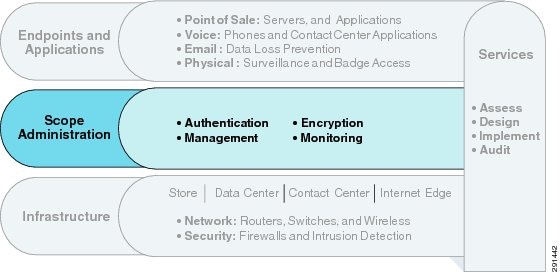
Scope Administration
The scope administration layer of the solution framework addresses the components such as authentication, encryption, management, and monitoring, as shown in Figure 4-20.
Figure 4-20 Scope Administration Layer of the Solution Framework
Authentication
Components Selected
•![]() Cisco Secure Access Control Server (ACS)
Cisco Secure Access Control Server (ACS)
•![]() Cisco Identity Services Engine (ISE)
Cisco Identity Services Engine (ISE)
•![]() RSA Authentication Manager
RSA Authentication Manager
•![]() Windows Active Directory
Windows Active Directory
Encryption
Components Selected
•![]() Cisco Security Manager
Cisco Security Manager
•![]() Cisco Key Manager
Cisco Key Manager
•![]() RSA Data Protection Manager
RSA Data Protection Manager
Management
Components Selected
•![]() EMC Ionix Network Configuration Manager (NCM)
EMC Ionix Network Configuration Manager (NCM)
•![]() Cisco Security Manager
Cisco Security Manager
•![]() Cisco Wireless Control Server Manager
Cisco Wireless Control Server Manager
•![]() EMC Unified Infrastructure Manager
EMC Unified Infrastructure Manager
•![]() VMware vSphere vCenter
VMware vSphere vCenter
•![]() Cisco Video Surveillance Manager
Cisco Video Surveillance Manager
•![]() Cisco Physical Access Manager
Cisco Physical Access Manager
•![]() RSA Archer
RSA Archer
Monitoring
Components Selected
•![]() RSA enVision
RSA enVision
•![]() HyTrust
HyTrust
•![]() EMC Ionix Network Configuration Manager (NCM)
EMC Ionix Network Configuration Manager (NCM)
Endpoints and Applications
The endpoints and applications layer of the solution framework addresses the components such as voice, e-mail, and physical security, as shown in Figure 4-21.
Figure 4-21 Endpoints and Applications Layer of the PCI Solution Framework

Voice
Components Selected
•![]() Cisco Unified Communications Manager
Cisco Unified Communications Manager
•![]() Cisco IP Phones (9971, 7975)
Cisco IP Phones (9971, 7975)
•![]() Cisco Survivable Remote Site Telephony (SRST)
Cisco Survivable Remote Site Telephony (SRST)
Components Selected
•![]() Cisco IronPort Email Security Appliance with Data Loss Prevention
Cisco IronPort Email Security Appliance with Data Loss Prevention
•![]() Microsoft Exchange Server 2008
Microsoft Exchange Server 2008
Physical
Components Selected
•![]() Cisco Physical Access Gateway
Cisco Physical Access Gateway
•![]() Cisco Video Surveillance Cameras (2421, 2500, 4500)
Cisco Video Surveillance Cameras (2421, 2500, 4500)
Note ![]() For a complete Bill of Materials, see "Bill Of Material." For assessment of components selected for PCI compliance, see Chapter 5, "Component Assessment." For complete running configurations of components, see "Detailed Full Running Configurations."
For a complete Bill of Materials, see "Bill Of Material." For assessment of components selected for PCI compliance, see Chapter 5, "Component Assessment." For complete running configurations of components, see "Detailed Full Running Configurations."
 Feedback