- About the Document
- Introduction
- ESX Server Network and Storage Connectivity
VMware Infrastructure 3 in a Cisco Network Environment
About the Document
This document is a collaboration between Cisco and VMware. It documents a set of suggested best practices for deploying VMware Infrastructure (VI) 3.x and VMware ESX Server 3.x in a Cisco network environment. The document provides details regarding the internal constructs of the ESX Server and their relation to external Cisco network devices are discussed.
This document is intended for network architects, network engineers, and server administrators interested in understanding and deploying VMware ESX Server 3.x hosts in a Cisco data center environment.
Introduction
Currently, there are efforts to consolidate and standardize the hardware and software platforms comprising the enterprise data center. IT groups are considering the data center facility, the servers it houses, and network components as a pool of resources rather than unrelated assets "siloed" to resolve specific business requirements. Server virtualization is a technique that allows the abstraction of server resources to provide flexibility and optimize usage on a standardized infrastructure. As a result, data center applications are no longer bound to specific hardware resources; thus making the application unaware of the underlying hardware, yet viewing the CPUs, memory, and network infrastructure as shared resource pools available via virtualization.
Virtualization of network, storage, and server platforms has been maturing over time. Technologies such as virtual local area networks (VLANs), virtual storage area networks (VSANs), and virtual network devices are widely deployed in today's enterprise data center. Mainframe legacy systems have been "virtualized" for many years, employing logical partitions (LPARs) to achieve greater resource utilization.
The ability to break the link between physical hardware (such as CPU, memory, and disk) from an operating system provides new opportunities to consolidate beyond the physical level and to optimize resource utilization and application performance. Expediting this revolution is the introduction of more powerful x86 platforms built to support a virtual environment, namely the availability of multi-core CPU and the use of AMD Virtualization (AMD-V) and the Intel Virtualization Technology (IVT).

Note ![]() For more information about AMD Processors that support this technology, refer to the following URL: http://www.amd.com/us-en/Processors/ProductInformation/0,,30_118_8796,00.html
For more information about AMD Processors that support this technology, refer to the following URL: http://www.amd.com/us-en/Processors/ProductInformation/0,,30_118_8796,00.html
For more information about Intel Processors that support this technology, refer to the following URL: http://www.intel.com/business/technologies/virtualization.htm?iid=servproc+rhc_virtualization
VMware infrastructure provides a rich set of networking capabilities that well integrate with sophisticated enterprise networks. These networking capabilities are provided by VMware ESX Server and managed by VMware VirtualCenter. With virtual networking, you can network both virtual machines and physical machines in a consistent manner. You can also build complex networks within a single ESX Server host or across multiple ESX Server hosts, where virtual switches allow virtual machines on the same ESX Server host to communicate with each other using the same network protocols that would be used over physical switches, without the need for additional networking hardware. ESX Server virtual switches also support VLANs that are compatible with standard VLAN implementations from other vendors.
A virtual machine can be configured with one or more virtual Ethernet adapters, each of which has its own IP address and MAC address. As a result, virtual machines have networking properties consistent with physical machines.
ESX Server Network and Storage Connectivity
VMWare networking is defined per ESX host, and is configured via the VMware VirtualCenter Management Server, the tool used to manage an entire virtual infrastructure implementation. An ESX Server host can run multiple virtual machines (VMs) and perform some switching internal to the host's virtual network prior to sending traffic out to the physical LAN switching network.
ESX Server Networking Components
Figure 1 VMware Networking is Defined per ESX Host
vmnics, vNICs and Virtual Ports
The term "NIC" has two meanings in a VMware virtualized environment; it can refer to a physical network adapters (vmnic) of the host server hardware and it can also refer to a virtual NIC (vNIC), a virtual hardware device presented to the virtual machine by VMware's hardware abstraction layer. While a vNIC is solely a virtual device, it can leverage the hardware acceleration features offer by the physical NIC.
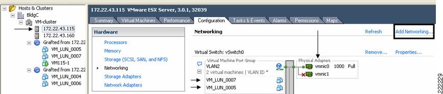
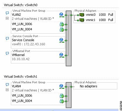
Through VirtualCenter, you can see the networking configuration by highlighting the ESX host of interest (on the left of the interface, see Figure 1). Within the Configuration tab (on the right side of the interface), you can find the association between the VM's vNICs (VM_LUN_0007 and VM_LUN_0005 in Figure 1) and the physical NICs (vmnic0 and vmnic1). The virtual and physical NICs are connected through a virtual switch (vSwitch). A vSwitch forwards the traffic between a vNIC and a vmnic, and the connection point between the vNIC and the vSwitch is called a virtual port.
Clicking the Add Networking button opens the Add Network Wizard, which guides you through the creation of new vSwitches or new Port Groups, a feature used to partition an existing vSwitch.
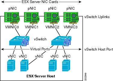
Figure 2 shows the provisioning of physical and VM adapters in an ESX host.
Figure 2 ESX Server Interfaces
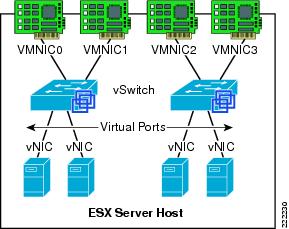
In Figure 2, four vmnics are presented on the physical host. The server administrator can designate which vmnics carry VM traffic. This ESX Server has been configured with two vSwitches. Four VMs are present, each configured with a single vNIC and the vNICs are in turn connected to the virtual ports of one of the vSwitches.
vNIC MAC Addresses, Bootup, VMotion Migration
VMs can be configured with up to four vNICs. The vNICs MAC addresses are generated automatically by the ESX Server (a process described in the next section); however, they may also be specified by the administrator. This feature can be useful when deploying VMs in an environment using DHCP-based server addressing, as a designated MAC address can be used to ensure a VM always receives the same IP address.
Note ![]() Unlike with regular NICs, it is not generally necessary or useful to "team" vNICs. In a VMware environment, NIC teaming refers to connecting multiple vmnics to a vSwitch to provide network load-sharing or redundancy.
Unlike with regular NICs, it is not generally necessary or useful to "team" vNICs. In a VMware environment, NIC teaming refers to connecting multiple vmnics to a vSwitch to provide network load-sharing or redundancy.
The vNIC MAC addresses include the Organization Unique Identifiers (OUI) assigned by IEEE to VMware. The ESX host and the configuration filename information is used to create a vNIC MAC address. The OUIs used by VMware are 00-50-56 and 00-0c-29. The algorithm used to generate the MAC address reduces the chances of a MAC address collision, although the process cannot guarantee a MAC address is unique. The generated MAC addresses are created using three parts:
•![]() The VMware OUI.
The VMware OUI.
•![]() The SMBIOS UUID for the physical ESX Server machine.
The SMBIOS UUID for the physical ESX Server machine.
•![]() A hash based on the name of the entity for which the MAC address is generated.
A hash based on the name of the entity for which the MAC address is generated.
The ESX host can detect a MAC collision between VMs and resolve the collision, if necessary. VMware has reserved the range 00:50:56:00:00:00 ‡ 00:50:56:3F:FF:FF for statically assigned VM MAC addresses. If an administrator wishes to assign static MAC addresses to VMs, they should use addresses within this range.
Each VM has a unique ".vmx" file; a file containing a VMs configuration information. The dynamically generated MAC address is saved in this file. If this file is removed, a VM's MAC address may change, as the location information of that file is included in the address generation algorithm.
Note ![]() VMotion is the method used by ESX Server to migrate powered-on VMs within an ESX Server farm from one physical ESX host to another. A VMotion migration does not cause the VM MAC to change. If a VM moves with a VMotion migration from an ESX host to a different one, the MAC address of the VM will not change because the VMware Virtual Machine File System (VMFS) volume is on a SAN and is accessible to both the originating ESX host and target ESX host. Therefore, there is no need to copy the .vmx configuration file and VM disk to a different location, which may trigger a new MAC generation.
VMotion is the method used by ESX Server to migrate powered-on VMs within an ESX Server farm from one physical ESX host to another. A VMotion migration does not cause the VM MAC to change. If a VM moves with a VMotion migration from an ESX host to a different one, the MAC address of the VM will not change because the VMware Virtual Machine File System (VMFS) volume is on a SAN and is accessible to both the originating ESX host and target ESX host. Therefore, there is no need to copy the .vmx configuration file and VM disk to a different location, which may trigger a new MAC generation.
Note ![]() This is not necessarily the case when you migrate (non-VMotion) a powered-off VM. In this situation, you can also decide to relocate the VM, which in turn may change the MAC address on the VM.
This is not necessarily the case when you migrate (non-VMotion) a powered-off VM. In this situation, you can also decide to relocate the VM, which in turn may change the MAC address on the VM.
ESX Virtual Switch
The ESX host links local VMs to each other and to the external enterprise network via a software virtual switch (vSwitch), which runs in the context of the kernel.
Virtual Switch Overview
Virtual switches are the key networking components in VMware Infrastructure 3. You can create up to 248 simultaneous virtual switches on each ESX Server 3 host. A virtual switch is "built to order" at run time from a collection of small functional units.
Some of the key functional units are:
•![]() The core layer forwarding engine—This engine is a key part of the system (for both performance and correctness), and in virtual infrastructure it is simplified so it only processes Layer 2 Ethernet headers. It is completely independent of other implementation details, such as differences in physical Ethernet adapters and emulation differences in virtual Ethernet adapters.
The core layer forwarding engine—This engine is a key part of the system (for both performance and correctness), and in virtual infrastructure it is simplified so it only processes Layer 2 Ethernet headers. It is completely independent of other implementation details, such as differences in physical Ethernet adapters and emulation differences in virtual Ethernet adapters.
•![]() VLAN tagging, stripping, and filtering units.
VLAN tagging, stripping, and filtering units.
•![]() Layer 2 security, checksum, and segmentation offload units.
Layer 2 security, checksum, and segmentation offload units.
When the virtual switch is built at run-time, ESX Server loads only those components it needs. It installs and runs only what is actually needed to support the specific physical and virtual Ethernet adapter types used in the configuration. This means the system pays the lowest possible cost in complexity and demands on system performance.
The design of ESX Server supports temporarily loading certain components in the field—a capability that could be used, for example, for running appropriately designed diagnostic utilities. An additional benefit of the modular design is that VMware and third-party developers can easily incorporate modules to enhance the system in the future.
In many ways, the ESX Server virtual switches are similar to physical switches. In some notable ways, they are different. Understanding these similarities and differences will help you plan the configuration of your virtual network and its connections to your physical network.
A Virtual Switch is Similar to a Physical Switch
A virtual switch, as implemented in ESX Server 3, works in much the same way as a modern Ethernet switch. It maintains a MAC address, port forwarding table, and performs the following functions:
•![]() Looks up each frame's destination MAC when it arrives.
Looks up each frame's destination MAC when it arrives.
•![]() Forwards a frame to one or more ports for transmission.
Forwards a frame to one or more ports for transmission.
•![]() Avoids unnecessary deliveries (in other words, it is not a hub).
Avoids unnecessary deliveries (in other words, it is not a hub).
An ESX Server 3 virtual switch supports VLAN segmentation at the port level. This means that each port can be configured in either of the following ways:
•![]() With access to a single VLAN, making it what is called an access port in the world of physical switches, or in ESX Server terminology using virtual switch tagging.
With access to a single VLAN, making it what is called an access port in the world of physical switches, or in ESX Server terminology using virtual switch tagging.
•![]() With access to multiple VLANs, leaving tags intact, making it what is called a trunk port in the world of physical switches, or in ESX Server terminology using virtual guest tagging.
With access to multiple VLANs, leaving tags intact, making it what is called a trunk port in the world of physical switches, or in ESX Server terminology using virtual guest tagging.
In addition, an administrator can manage many configuration options for the switch as a whole and for individual ports using the Virtual Infrastructure Client.
A Virtual Switch Is Different from a Physical Switch
ESX Server provides a direct channel from virtual Ethernet adapters for such configuration information as authoritative MAC filter updates. Therefore, there is no need to learn unicast addresses or perform IGMP snooping to learn multicast group membership.
Spanning Tree Protocol not Used on the Virtual Switch
VMware infrastructure enforces a single-tier networking topology within the ESX Server. In other words, there is no way to interconnect multiple virtual switches; thus, the ESX network cannot be configured to introduce loops. Because of this, the vSwitch on the ESX host does not execute the Spanning Tree Protocol (STP).
Note ![]() It is actually possible, with some effort, to introduce a loop with virtual switches. However, to do so, you must run Layer 2 bridging software in a guest with two virtual Ethernet adapters connected to the same subnet. This would be difficult to do accidentally, and there is no reason to do so in typical configurations.
It is actually possible, with some effort, to introduce a loop with virtual switches. However, to do so, you must run Layer 2 bridging software in a guest with two virtual Ethernet adapters connected to the same subnet. This would be difficult to do accidentally, and there is no reason to do so in typical configurations.
Virtual Switch Isolation
Network traffic cannot flow directly from one virtual switch to another virtual switch within the same host. Virtual switches provide all the ports you need in one switch, leading to the following benefits:
•![]() Because there is no need to cascade virtual switches, virtual infrastructure provides no capability to connect virtual switches.
Because there is no need to cascade virtual switches, virtual infrastructure provides no capability to connect virtual switches.
•![]() Because there is no way to connect virtual switches, there is no need to prevent bad virtual switch connections.
Because there is no way to connect virtual switches, there is no need to prevent bad virtual switch connections.
•![]() Because virtual switches cannot share physical Ethernet adapters, there is no way to fool the Ethernet adapter into doing loopback or some similar configuration that would cause a leak between virtual switches.
Because virtual switches cannot share physical Ethernet adapters, there is no way to fool the Ethernet adapter into doing loopback or some similar configuration that would cause a leak between virtual switches.
In addition, each virtual switch has its own forwarding table, and there is no mechanism to allow an entry in one table to point to a port on another virtual switch. In other words, every destination the switch looks up can match only ports on the same virtual switch as the port where the frame originated, even if other virtual switches' lookup tables contain entries for that address.
There are natural limits to this isolation. If you connect the uplinks of two virtual switches together, or if you bridge two virtual switches with software running in a virtual machine.
Uplink Ports
Uplink ports are ports associated with physical adapters, providing a connection between a virtual network and a physical network. Physical adapters connect to uplink ports when they are initialized by a device driver or when the teaming policies for virtual switches are reconfigured. Some virtual switches should not connect to a physical network and thus have no uplink port. This is the case, for example, for a virtual switch that provides connections between a firewall virtual machine and the virtual machines protected by the firewall.
Virtual Ethernet adapters connect to virtual ports when you power on or resume the virtual machine on which the adapters are configured, when you take an explicit action to connect the device, or when you migrate a virtual machine using VMotion. A virtual Ethernet adapter updates the virtual switch port with MAC filtering information when it is initialized and whenever it changes. A virtual port may ignore any requests from the virtual Ethernet adapter that would violate the Layer 2 security policy in effect for the port. For example, if MAC spoofing is blocked, the port drops any packets that violate this rule.
Virtual Switch Correctness
Two correctness issues are particularly important. It is important to ensure that virtual machines or other nodes on the network cannot affect the behavior of the virtual switch. ESX Server guards against such influences in the following ways:
•![]() Virtual switches do not learn MAC addresses from the network in order to populate their forwarding tables. This eliminates a likely vector for denial- of-service (DoS) or leakage attacks, either as a direct denial of service attempt or, more likely, as a side effect of some other attack, such as a worm or virus as it scans for vulnerable hosts to infect.
Virtual switches do not learn MAC addresses from the network in order to populate their forwarding tables. This eliminates a likely vector for denial- of-service (DoS) or leakage attacks, either as a direct denial of service attempt or, more likely, as a side effect of some other attack, such as a worm or virus as it scans for vulnerable hosts to infect.
•![]() Virtual switches make private copies of any frame data used to make forwarding or filtering decisions. This is a critical feature of the virtual switch and is unique to virtual switches. The virtual switch does not copy the entire frame, because that would be inefficient, but ESX Server must make sure that the guest operating system does not have access to any sensitive data once the frame is passed on to the virtual switch.
Virtual switches make private copies of any frame data used to make forwarding or filtering decisions. This is a critical feature of the virtual switch and is unique to virtual switches. The virtual switch does not copy the entire frame, because that would be inefficient, but ESX Server must make sure that the guest operating system does not have access to any sensitive data once the frame is passed on to the virtual switch.
ESX Server ensures that frames are contained within the appropriate VLAN on a virtual switch. It does so in the following ways:
•![]() VLAN data is carried outside the frame as it passes through the virtual switch. Filtering is a simple integer comparison. This is really just a special case of the general principle that the system should not trust user accessible data.
VLAN data is carried outside the frame as it passes through the virtual switch. Filtering is a simple integer comparison. This is really just a special case of the general principle that the system should not trust user accessible data.
•![]() Virtual switches have no dynamic trunking support.
Virtual switches have no dynamic trunking support.
VLANs in VMware Infrastructure
VLANs provide for logical groupings of stations or switch ports, allowing communications as if all stations or ports were on the same physical LAN segment. Confining broadcast traffic to a subset of the switch ports or end users saves significant amounts of network bandwidth and processor time.
In order to support VLANs for VMware infrastructure users, one of the elements on the virtual or physical network has to tag the Ethernet frames with 802.1Q tag. There are three different configuration modes to tag (and untag) the packets for virtual machine frames.
•![]() Virtual switch tagging (VST mode)—This is the most common configuration. In this mode, you provision one Port Group on a virtual switch for each VLAN, then attach the virtual machine's virtual adapter to the Port Group instead of the virtual switch directly. The virtual switch Port Group tags all outbound frames and removes tags for all inbound frames. It also ensures that frames on one VLAN do not leak into a different VLAN. Use of this mode requires that the physical switch provides a trunk.
Virtual switch tagging (VST mode)—This is the most common configuration. In this mode, you provision one Port Group on a virtual switch for each VLAN, then attach the virtual machine's virtual adapter to the Port Group instead of the virtual switch directly. The virtual switch Port Group tags all outbound frames and removes tags for all inbound frames. It also ensures that frames on one VLAN do not leak into a different VLAN. Use of this mode requires that the physical switch provides a trunk.
•![]() Virtual machine guest tagging (VGT mode)—You may install an 802.1Q VLAN trunking driver inside the virtual machine, and tags will be preserved between the virtual machine networking stack and external switch when frames are passed from or to virtual switches. Use of this mode requires that the physical switch provides a trunk.
Virtual machine guest tagging (VGT mode)—You may install an 802.1Q VLAN trunking driver inside the virtual machine, and tags will be preserved between the virtual machine networking stack and external switch when frames are passed from or to virtual switches. Use of this mode requires that the physical switch provides a trunk.
•![]() External switch tagging (EST mode) —You may use external switches for VLAN tagging. This is similar to a physical network and VLAN configuration is normally transparent to each individual physical server. There is no need to provide a trunk in these environments.
External switch tagging (EST mode) —You may use external switches for VLAN tagging. This is similar to a physical network and VLAN configuration is normally transparent to each individual physical server. There is no need to provide a trunk in these environments.
Port Groups
Virtual machines connect to vSwitches through vNICs. The networking configuration on the ESX Server associates vNIC (also referred to VM Network Adapter) with a Network Label, which in turn identifies a Port Group. In other words, to associate a VM with a vSwitch, you need to assign a vNIC to a Port Group.
VM Assignment to a VLAN
Figure 3 shows the relationship between Port Group and VLANs. In Figure 3, to the left you see the VM Network Adapter configuration with the Network Connection settings referencing one of the available Port Groups. To the right you see the Virtual Switch Properties for a given Port Group, the Network Label and the VLAN associated with it.
Figure 3 Relation Between Port Groups and VLANs
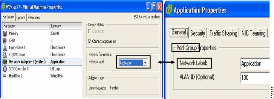
The association of a VM Network Adapter (vNIC) to a Port Group (i.e., Network Label) does the following:
•![]() Assigns the vNIC to a vSwitch.
Assigns the vNIC to a vSwitch.
•![]() Assigns the vNIC to a specific VLAN.
Assigns the vNIC to a specific VLAN.
•![]() Assigns the vNIC to a specific "NIC Teaming" policy (this is explained in further detail in a later section as this is not vNIC teaming, nor NIC teaming in the traditional sense). It would be more appropriate to say that traffic from the VM is going to exit the vSwitch to the LAN switching network according to a traffic load-balancing policy defined by the Port Group "NIC Teaming" configuration.
Assigns the vNIC to a specific "NIC Teaming" policy (this is explained in further detail in a later section as this is not vNIC teaming, nor NIC teaming in the traditional sense). It would be more appropriate to say that traffic from the VM is going to exit the vSwitch to the LAN switching network according to a traffic load-balancing policy defined by the Port Group "NIC Teaming" configuration.
Port Groups are NOT VLANs
Port Groups are configuration templates for the vNIC ports on the vSwitch. Port Groups allow administrators to group vNICs from multiple VMs and configure them simultaneously. The administrator can set specific QoS, security policies, and VLANs by changing the Port Group configuration.
Even if Port Groups assign vNICs (thus VMs) to a VLAN, there is no 1-to-1 mapping between Port Groups and VLANs; in fact, you could have any number of different Port Groups using the same VLAN.
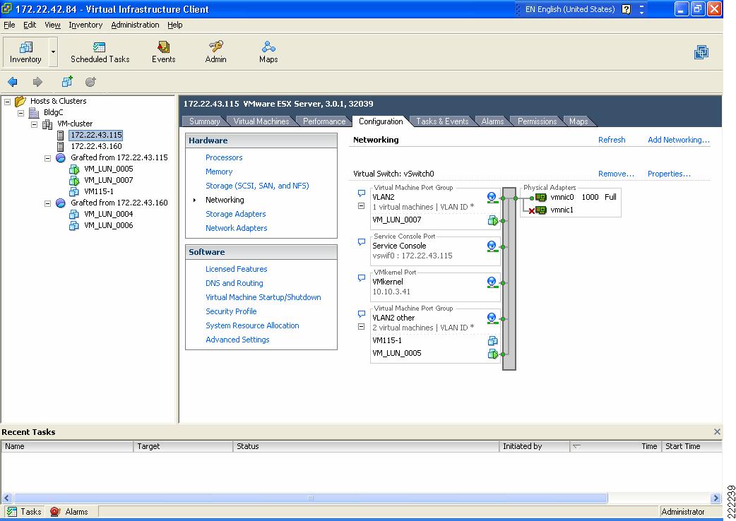
Consider Figure 4 as an example. VM_LUN_0007 and VM_LUN_0005 are on two different Port Groups, the first called VLAN2 and the second called VLAN2 other. Both Port Groups are using VLAN2, in fact VM_LUN_0007 can talk to VM_LUN_0005. Port Groups thus do not partition the switch ports by isolating them, but simply by grouping them from a configuration point of view.
Figure 4 vSwitch and Port Groups
Summary
The Port Group concept may be sometimes misunderstood by networking experts. As a summary these are key concepts to retain regarding Port Groups:
•![]() Port Groups are a configuration management mechanism.
Port Groups are a configuration management mechanism.
•![]() Port Groups are not VLANs.
Port Groups are not VLANs.
•![]() Port Groups are not Port-Channels.
Port Groups are not Port-Channels.
•![]() The association between a VM and a vSwitch is defined by selecting a Port Group (called Network Label) from the vNIC (VM Network Adapter) configuration screen.
The association between a VM and a vSwitch is defined by selecting a Port Group (called Network Label) from the vNIC (VM Network Adapter) configuration screen.
•![]() Port Groups define the following configuration parameters for the vNIC ports that belong to them: VLAN number, Layer 2 security policy, QoS policy, and traffic load-balancing policy referred to as NIC Teaming.
Port Groups define the following configuration parameters for the vNIC ports that belong to them: VLAN number, Layer 2 security policy, QoS policy, and traffic load-balancing policy referred to as NIC Teaming.
Layer 2 Security Features
The virtual switch has the ability to enforce security policies to prevent virtual machines from impersonating other nodes on the network. There are three components to this feature.
•![]() Promiscuous mode is disabled by default for all virtual machines. This prevents them from seeing unicast traffic to other nodes on the network.
Promiscuous mode is disabled by default for all virtual machines. This prevents them from seeing unicast traffic to other nodes on the network.
•![]() MAC address change lockdown prevents virtual machines from changing their own unicast addresses. This also prevents them from seeing unicast traffic to other nodes on the network, blocking a potential security vulnerability that is similar to but narrower than promiscuous mode.
MAC address change lockdown prevents virtual machines from changing their own unicast addresses. This also prevents them from seeing unicast traffic to other nodes on the network, blocking a potential security vulnerability that is similar to but narrower than promiscuous mode.
•![]() Forged transmit blocking, when you enable it, prevents virtual machines from sending traffic that appears to come from nodes on the network other than themselves.
Forged transmit blocking, when you enable it, prevents virtual machines from sending traffic that appears to come from nodes on the network other than themselves.
Management
The following are three approaches to managing an ESX Server:
•![]() Service Console
Service Console
•![]() Web-based User Interface
Web-based User Interface
•![]() Management application such as VMware VirtualCenter
Management application such as VMware VirtualCenter
The Service Console on ESX Server is accessible via SSH, Telnet, HTTP, and FTP. In addition, the Service Console supplies authentication and system monitoring services. Note that the embedded version of ESX Server, ESX 3i, has no user accessible Service Console, but still supports a web interface for management. The Service Console and web-based user interface are sufficient for managing a single ESX host.
VMware VirtualCenter is a central management solution that, depending on the VC platform, scales to support numerous clients, ESX hosts, and VMs. VirtualCenter provides tools for building and maintaining your virtual network infrastructure. You can use VirtualCenter to add, delete, and modify virtual switches and to configure Port Groups with VLANs and teaming.
A sample configuration is visible from the VMware ESX Server/Configuration/Networking tab, as shown in Figure 5. In this example, the VM called W2K-WS2 connects to vSwitch2 on VLAN 100 (shown in Figure 5 as truncated to VLAN *).
Figure 5 vSwitch Final Configuration
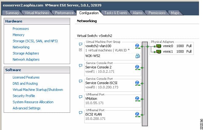
The characteristics of a vSwitch can be further modified by selecting the Properties button to the right of the vSwitch. This allows adding more Port Groups, changing the NIC Teaming properties, configure traffic rate limiting, etc.
You can use the VirtualCenter roles feature to assign the permissions a network administrator needs to manage the virtual network. For detailed discussion, see Managing VMware VirtualCenter Roles and Permissions document available at http://www.vmware.com/vmtn/resources/826.
vSwitch Scalability
An ESX Server may contain multiple vSwitches, each of which can be configured with up to 1016 "internal" virtual ports for VM use. Because each vNIC assigned to the vSwitch uses one virtual port, this yields a theoretical maximum of 1016 VMs per vSwitch. The virtual switch connects to the enterprise network via outbound vmnic adapters. A maximum of 32 vmnics may be used by the virtual switch for external connectivity.
Incorrect Configurations with vSwitches
Certain configurations are not allowed with vSwitches:
•![]() vSwitches cannot be directly connected to each other. In other words, only vNICs and vmnics can connect to a vSwitch. It is possible to pass traffic from one vSwitch to another vSwitch by using a VM with two vNICs and leveraging the bridging functionality of Microsoft Windows, for example. This practice should be avoided due to the risk of introducing Layer 2 loops.
vSwitches cannot be directly connected to each other. In other words, only vNICs and vmnics can connect to a vSwitch. It is possible to pass traffic from one vSwitch to another vSwitch by using a VM with two vNICs and leveraging the bridging functionality of Microsoft Windows, for example. This practice should be avoided due to the risk of introducing Layer 2 loops.
•![]() A vmnic and its associated physical NIC cannot belong to more than one vSwitch.
A vmnic and its associated physical NIC cannot belong to more than one vSwitch.
•![]() A vSwitch should not and, in fact, cannot become a transit path for the LAN switching network (see vSwitch Forwarding Characteristics for more information).
A vSwitch should not and, in fact, cannot become a transit path for the LAN switching network (see vSwitch Forwarding Characteristics for more information).
ESX LAN Networking
A virtual switch uses at least one of the vmnics on the physical server to link VMs to the external network. The VMkernel allows the vSwitch software construct to use some of the hardware acceleration features available on the physical NICs, including the following:
•![]() TCP segmentation offload
TCP segmentation offload
•![]() VLAN tagging
VLAN tagging
•![]() Checksum calculations offload
Checksum calculations offload
vSwitch Forwarding Characteristics
The vSwitch operates like a regular Layer 2 Ethernet switch. The vSwitch forwards traffic among VMs and between VMs and the LAN switching infrastructure. The ESX Server vmnics are the vSwitch uplinks. See Figure 6.
Figure 6 vSwitch Components
The areas of similarity for vSwitches and regular Ethernet switches are:
•![]() Forwarding is based on the MAC address.
Forwarding is based on the MAC address.
•![]() Traffic from VM-to-VM within the same vSwitch and VLAN remains local.
Traffic from VM-to-VM within the same vSwitch and VLAN remains local.
•![]() vSwitches can tag traffic with a VLAN ID.
vSwitches can tag traffic with a VLAN ID.
•![]() vSwitches are capable of trunking (802.1Q trunks without negotiation protocols).
vSwitches are capable of trunking (802.1Q trunks without negotiation protocols).
•![]() vSwitches can perform some QoS functions (rate limiting).
vSwitches can perform some QoS functions (rate limiting).
•![]() vSwitches implement some Layer 2 security functions.
vSwitches implement some Layer 2 security functions.
•![]() vSwitches are capable of establishing port channels (without negotiation protocols).
vSwitches are capable of establishing port channels (without negotiation protocols).
Areas where vSwitches and regular Ethernet switches differ are:
•![]() vSwitches forwarding table is programmed by a notification mechanism between VMs and the vSwitch. The vSwitch does not learn MAC addresses from the network.
vSwitches forwarding table is programmed by a notification mechanism between VMs and the vSwitch. The vSwitch does not learn MAC addresses from the network.
•![]() vSwitches do not run or require Spanning Tree Protocol (STP), as traffic received on an uplink is never forwarded to another uplink.
vSwitches do not run or require Spanning Tree Protocol (STP), as traffic received on an uplink is never forwarded to another uplink.
•![]() vSwitches do not perform IGMP snooping; however, multicast traffic is not flooded as the vSwitch knows the multicast interest of all the vNICs.
vSwitches do not perform IGMP snooping; however, multicast traffic is not flooded as the vSwitch knows the multicast interest of all the vNICs.
•![]() vSwitches' port mirroring capabilities are a subset of SPAN capabilities.
vSwitches' port mirroring capabilities are a subset of SPAN capabilities.
Note ![]() For information from VMware: http://www.vmware.com/files/pdf/virtual_networking_concepts.pdf
For information from VMware: http://www.vmware.com/files/pdf/virtual_networking_concepts.pdf
vSwitch Forwarding Table
The vSwitch has a Layer 2 forwarding table that it uses to forward traffic based on the destination MAC address. The vSwitch forwarding table contains the MAC address for the VMs and their associated virtual ports. When a frame is destined for a VM, the vSwitch sends the frame directly to the VM. When the destination MAC address does not exist in the VM, or it is multicast or broadcast, it sends the traffic out to the vmnics (i.e., to the server NIC ports).
If multiple vmnics (physical NICs) are present, multicast and broadcast traffic is not flooded to all vmnics in the same VLAN. This happens regardless of the NIC teaming configuration—with an active/standby configuration this is self-explanatory, with an active/active configuration this is also the case because at any given time each VM only uses one vmnic to forward the traffic.
In summary, a regular Ethernet switch learns the forwarding table based on traffic seen on its ports; on the other hand, in a vSwitch, the forwarding table contains only the MAC addresses of the VMs and everything that does not match the VM entries goes out to the server NIC cards, including broadcasts and multicast traffic.
vSwitch Loop Prevention
The configuration of redundant vSwitch uplinks is addressed in Using NIC Teaming for Connectivity Redundancy. Realize for now that vSwitches do not run or require STP so the vSwitch implements other loop prevention mechanisms. These loop prevention mechanisms include dropping inbound traffic for possible returning frames, and distance vector like logic where, for example, a frame that enters from one NIC (uplink) is not going to go out of the ESX Server from a different NIC card (this would be otherwise the case for, say, broadcasts).
Examples help clarify these behaviors. Figure 7 represents a typical "looped" design, which means a topology that without an STP would not work because of a Layer 2 loop is present. Figure 7 shows the behavior of a vSwitch when a broadcast enters the ESX NIC1. If the vSwitch was running Spanning Tree, NIC2 would be in blocking state, thus preventing the broadcast from going out on NIC2. Unlike a regular switch, the vSwitch does not run Spanning Tree, but it does not forward the broadcast out of NIC2 either, which is desirable.
Figure 7 vSwitch and Broadcasts
Now consider a loop-free topology (see the left side of Figure 8), which is a topology where no intrinsic loop exist. This is a topology where Spanning Tree is not really needed, except as a loop-prevention mechanism. In this topology the upstream routers need to exchange HSRP hellos to provide a redundant gateway. If the vSwitch was a normal Ethernet switch, the HSRP hellos would allow the two routers to agree on which one of the two is going to be active and which one is going to be standby for the gateway function. Because the HSRPs advertisements need to go through a vSwitch, in this case the two routers will not be able to converge, both of them believe they are active for the HSRP gateway function. The reason is that the vSwitch does not pass the HSRP datagrams. An example topology that would solve this specific problem (but not necessarily the best possible design) for this to work would be the topology to the right in Figure 8.
Figure 8 vSwitch and HSRP Traffic
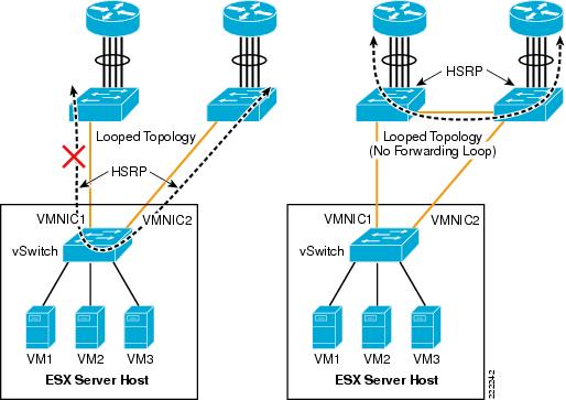
Note ![]() The above examples do not constitute design recommendations, they are included in this document to clarify the forwarding and loop prevention characteristics of a vSwitch compared to a regular Ethernet switch. For design recommendations refer to ESX Server Network and Storage Connectivity.
The above examples do not constitute design recommendations, they are included in this document to clarify the forwarding and loop prevention characteristics of a vSwitch compared to a regular Ethernet switch. For design recommendations refer to ESX Server Network and Storage Connectivity.
VLAN Tagging
Physical access switches in the data center provide the VLAN tagging functionality, allowing a single network infrastructure to support multiple VLANs. With the introduction of ESX Server into the data center, the traditional method of VLAN tagging is no longer the only option.
vSwitches support VLAN tagging. You can configure a vSwitch to pass traffic from the VM as is, without any VLAN TAG, to the Cisco switch upstream connected to the ESX Server NICs. VMware calls this method External Switch Tagging (EST). You can also configure the vSwitch in such a way that it preserves the VLAN TAG assigned by the VM Guest OS when passing the traffic to the upstream Cisco switch connected to the ESX Server NICs. VMware calls this method Virtual Guest Tagging (VGT).
The most common and preferred option is to configure the vSwitch to color traffic from the VMs with a VLAN TAG and to establish a 802.1q trunk with the Cisco switch connected to the ESX Server NICs. VMware calls this method Virtual Switch Tagging (VST).
Note ![]() VMware information can be found at: http://www.vmware.com/pdf/esx3_vlan_wp.pdf.
VMware information can be found at: http://www.vmware.com/pdf/esx3_vlan_wp.pdf.
This section of the document discusses the benefits and drawbacks of each of these (EST, VTG, and VST) approaches.
External Switch Tagging
EST defines VLAN tagging at the access port of the ESX host. From a VMware configuration point of view, EST is achieved by specifying VLAN 0 in the VLAN ID field of the Port Group configuration, or simply by leaving the VLAN ID empty.
Contrary to what one may think, there is no 1-to-1 mapping between the vNIC and the vmnics. Local switching on the vSwitch still happens. When the traffic from a VM goes out to the Cisco Catalyst switch, the vSwitch does not prepend any 802.1q VLAN label.
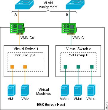
In Figure 9, each virtual switch is associated with a single VLAN: VLANs A and B. The external network defines the vmnic links to the virtual switches as access ports supporting a single VLAN per port. The vSwitch does not perform any VLAN tag functions. VM1-to-VM2 traffic is switched on Virtual Switch 1 without going out of vmnic0. If VM1 (or VM2) traffic is not directed to VM2 (or VM1), it goes out of vmnic0 and the Cisco Catalyst switch assigns it to VLAN A.
Similarly, traffic among VM30, VM31, VM32 is switched on vSwitch2 without going out of vmnic1. If either VM30, VM31, or VM32 send traffic to a different destination than the VMs on Virtual Switch 2, traffic goes out of vmnic1 and the Cisco Catalyst switch assigns it to VLAN B.
Figure 9 External Switch Tagging
Virtual Guest Tagging
VGT requires that each VM guest operating system supports and manages 802.1q tags. The VM manages the vNIC, removing all tagging responsibilities from the virtual switch. Disabling 802.1q tag support on the vSwitch can be done by setting the VLAN field to 4095 in the Port Group configuration. The vNIC driver may need to be set to e1000.
A VGT configuration requires more processing power from each VM, reducing the efficiency of the VM and overall ESX host. VGT deployments are uncommon but are necessary if a single VM must support more than four VLANs.
Note ![]() Each VM can have up to four independent vNIC which could reside on separate VLANs. As a result, there is no need to use the VGT mode if you need to place a VM on different VLANs. The vlance and vmxnet vNIC drivers do not support VGT. If you need to run VGT, you need to configure the VM vNIC driver to be e1000.
Each VM can have up to four independent vNIC which could reside on separate VLANs. As a result, there is no need to use the VGT mode if you need to place a VM on different VLANs. The vlance and vmxnet vNIC drivers do not support VGT. If you need to run VGT, you need to configure the VM vNIC driver to be e1000.
Virtual Switch Tagging
Virtual Switch Tagging (VST) allows the virtual switch to perform the 802.1q tag process. The VMkernel allows the physical adapters to carry out the VLAN tag operations, relieving the VMkernel of the work and improving overall system performance. VST requires that the vmnics connected to the vSwitch be 802.1q trunks. Note that this does not require any special configuration on the ESX host. The external network ports need to be configured to be 802.1q trunks as well.
Figure 10 shows a logical view of VST.
Figure 10 Virtual Switch Tagging

The vNICs of the VM are assigned to a Port Group that is associated with a specific VLAN, in this case VLANs "A" and "B". The vSwitch defines the vmnics as ports supporting all of the VLANs within the switch; that is, as trunks.
Note ![]() The Dynamic Trunking Protocol (DTP) allows negotiating the creation of a trunk between two switches. DTP is not supported by ESX virtual switches. This means that the Cisco Catalyst switch connecting to a vSwitch needs to be configured for static trunking.
The Dynamic Trunking Protocol (DTP) allows negotiating the creation of a trunk between two switches. DTP is not supported by ESX virtual switches. This means that the Cisco Catalyst switch connecting to a vSwitch needs to be configured for static trunking.
In VST mode, the vSwitch may support numerous VLANs over a limited number of ports, which allows the server administrator to define more VLANs than physical adapters.
Native VLAN
By default, the Cisco Catalyst switches can take traffic on the native VLAN that is not tagged and assign a VLAN tag to it. The vlan dot1q tag native configuration option on the Cisco Catalyst switches controls whether or not the switch needs to expect traffic to come into the port with or without the VLAN tag for the native VLAN. If a Port Group on the vSwitch uses the "native VLAN" according to the VST deployment scheme, it forwards traffic on the native VLAN with a 802.1q VLAN TAG. The vSwitch also expects the traffic coming from the Cisco switch on the native VLAN to be tagged. For the upstream Cisco switch port trunk to be compatible with this configuration, you need to configure the vlan dot1q tag native command on the Cisco switch.
Consider now a deployment of a mix of VST and EST mode. This means that some Port Groups define a VLAN ID, but other Port Group on the vSwitch use no VLAN ID, according to the EST deployment scheme. The traffic from these Port Groups belongs to the same VLAN (i.e., no VLAN on the vSwitch) and is colored by the Cisco Catalyst switch with the native VLAN configured on the switchport. In this case you need to disable the vlan dot1q tag native command on the Cisco Catalyst switch.
Using NIC Teaming for Connectivity Redundancy
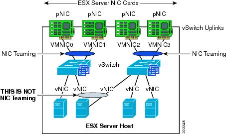
In the context of VMWare networking, NIC Teaming refers to the configuration of redundant ESX Server NIC cards that are used as vSwitch uplinks. This is also referred to as bonding. As Figure 11 shows, NIC teaming refers to creating a redundant vmnic configuration and not a redundant vNIC configuration. ESX NIC teaming is configured at the Port Group level. A redundant configuration on the ESX Server involves configuring vSwitches and/or Port Groups with redundant connectivity to the access layer.
Note ![]() Do not look for the NIC vendor specific NIC teaming software to configure ESX Server NIC teaming. ESX NIC teaming refers to the vSwitch "uplinks" (vmnic) configuration.
Do not look for the NIC vendor specific NIC teaming software to configure ESX Server NIC teaming. ESX NIC teaming refers to the vSwitch "uplinks" (vmnic) configuration.
Although it is possible to configure a VM with multiple vNICs, this configuration does not add any redundancy or performance because vSwitches and VMs are all software constructs that run within the VMkernel. Configuring redundant vSwitch uplinks adds redundancy and possibly performance by leveraging different physical network paths and multiple physical NIC cards or ports.
NIC teaming allows to bundle heterogeneous NIC cards together in order to minimize the chance of losing network connectivity due to a PCI card failure. Just like normal NIC teaming on servers, the NICs need to be part of the same Layer 2 domain.
Figure 11 Meaning of NIC Teaming for an ESX Server
NIC teaming offers several configuration options which can be implemented per-vSwitch or per Port Group:
•![]() Active/Standby.
Active/Standby.
•![]() Active/Active with load balancing based on VM Port-ID.
Active/Active with load balancing based on VM Port-ID.
•![]() Active/Active with load balancing based on the VM MAC-address hash.
Active/Active with load balancing based on the VM MAC-address hash.
•![]() Active/Active with load balancing based on the hash of the source and destination IP address. VMWare calls this IP-based hashing. Cisco calls this configuration Port-channeling.
Active/Active with load balancing based on the hash of the source and destination IP address. VMWare calls this IP-based hashing. Cisco calls this configuration Port-channeling.
Active/Active Port-based and MAC-based
With active/active mode, all the NICs (vmnics) in the team forward and receive traffic. NICs can be attached to different Cisco Catalyst switches or to a single switch, although using separate switches is more common for reasons of redundancy. The VMware virtual switch load balances egress traffic across the teamed vmnics via the source vNIC MAC address (MAC-based mode) or based on the Virtual Port ID (Port-based). The virtual switch uses all vmnics in the team. If a link failure occurs, the vSwitch reassigns VM traffic to the remaining functional interfaces defined in the team.
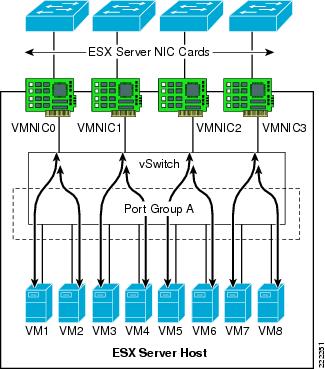
With either mode, a network traffic from a VM gets assigned to one vmnics for as long as the vmnic is functioning. Traffic from VMs are on average equally spread on all the available vmnics. For example, if there were four NICs in the team, and eight VMs, there would be two VMs using each NIC.
See Figure 12 for clarification. In this example, VM1 and VM2 use vmnic0, VM3 and VM4 use vmnic1, and so on. Vmnic0 could be connected to one Layer 2 switch, vmnic1 could connect to the same or a different Layer 2 switch, vmnic3 could connect to the same or a different switch, and so on. There is no requirement for the vmnics or VMs to be on the same or different VLANs just like there is no special requirement for the vmnics to connect to one single switch or multiple switches.
This active/active teaming mechanism ensures consistent mapping between the MAC of VMs and the Cisco LAN switches ports for both inbound and outbound traffic. The MAC moves to a different vmnic (thus a different Cisco LAN switchport) only when one of the vmnics fails, or if the VM is administratively moved (for example to a different ESX Server).
Figure 12 vSwitch NIC Teaming Active/Active Traffic Distribution
Active/Active IP-based (Port-Channeling)
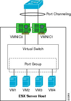
An EtherChannel (also known as 802.3ad link aggregation) bundles individual Ethernet links into a single logical link that provides the aggregate bandwidth of up to eight physical links. In VMware terminology this is referred to as IP-based load balancing and is found in the NIC teaming configuration of the ESX host. The IP-based load balancing configuration distributes outbound traffic from the VM based on the hash of the source and destination IP addresses. For this load-balancing method to work, you need to configure EtherChanneling (i.e., 802.3ad link aggregation) on the Cisco LAN switch that the vmnics connect to.
On a Cisco switch, you can configure EtherChannels manually or you can use the Port Aggregation Control Protocol (PAgP) or the 802.3ad Link Aggregation Control Protocol (LACP) to form EtherChannels. The EtherChannel protocols allow ports with similar characteristics to form an EtherChannel through dynamic negotiation with connected network devices. PAgP is a Cisco-proprietary protocol and LACP is defined in IEEE 802.3ad. Cisco switches support both protocols.
On the ESX host, the vSwitch IP-based load balancing does not run the 802.3ad LACP. For this reason, the EtherChannel configuration on the Cisco Catalyst switch can not use dynamic negotiation, which means that the channel-group is set to ON in the configuration. Note that such a configuration is static in that both the Cisco Catalyst switch and the vSwitch perform load distribution on the bundled links (with their respective load balancing algorithm) on either side, regardless of whether the other end of the bundle is configured for channeling or not.
Figure 13 shows this NIC teaming method. All NICs connect to a single switch (or to multiple switches "clustered" together with proper technology). All NIC ports that are member of the same IP-based NIC teaming configuration must be member of the same Port-channel on the Cisco LAN switch.
Note ![]() For more information on configuring EtherChanneling on the Cisco Catalyst switches, refer to the following URL:
For more information on configuring EtherChanneling on the Cisco Catalyst switches, refer to the following URL:
http://www.cisco.com/en/US/partner/docs/switches/lan/catalyst6500/ios/12.2SX/configuration/guide/channel.html
Note ![]() It is possible to connect an ESX Server to multiple Cisco Catalyst 6500 switches configured for Virtual Switching System (VSS), or multiple Cisco Blade Switches (CBS) configured for Virtual Blade Switching (VBS), and configure NIC teaming for IP-based hashing.
It is possible to connect an ESX Server to multiple Cisco Catalyst 6500 switches configured for Virtual Switching System (VSS), or multiple Cisco Blade Switches (CBS) configured for Virtual Blade Switching (VBS), and configure NIC teaming for IP-based hashing.
Figure 13 vSwitch EtherChanneling
Teaming Failback
The Teaming Failback feature controls the preemption behavior of NIC teaming. For example, assume that you have two vmnics: vmnic0 and vmnic1. After vmnic0 fails, traffic is sent to vmnic1. When vmnic0 becomes available, the default behavior (Teaming Failback set to ON) is for traffic to be reassigned to vmnic0.
This poses a risk of blackholing traffic when on the LAN switching side there is a linkup but the port does not go into forwarding mode right away. This problem can be easily addressed on the Cisco Catalyst switch side by using trunkfast and by setting the trunk mode to ON. The problem can also be addressed from the ESX host side, by disabling the Teaming Failback feature, which means that after vmnic0 gets a linkup again, the NIC is still kept inactive up until the currently active vmnic1 fails.
In releases prior to ESX 3.5, the Teaming Failback mode is enabled by disabling Rolling Failover. Failback = No (ESX 3.5) is equivalent to Rolling Failover = Yes (releases prior to ESX 3.5) and vice versa.
Beaconing
Beaconing is a probing function that allows the ESX host to monitor the availability of vmnics within a team. Beaconing requires that the vmnics reside in the same broadcast domain. Beacons are intended for use with teams connected to more than one external switch. The ESX Server monitors the loss of beacon probes to determine failures in the external network. If a failure condition exists, meaning that a vmnic has not reported receiving x number of beacons from the beacon initiator, the ESX Server toggles adapters and declares the primary adapter down.
The beacon frames are Layer 2 frames, with Ethertype 0x05ff with source MAC address equal to the burnt-in-address of the NIC card (not the VMware MAC address) and a broadcast destination address. Frames are sent on every VLAN that the vSwitch is on.
Note ![]() Beaconing is configured per Port Group.
Beaconing is configured per Port Group.
It is not recommended to use beaconing as a form of external network failure detection because of the possibility of false positives and its inability to detect upstream failures. To provide a highly available external network infrastructure, use redundant paths and/or protocols with network-based load-balancing to achieve high availability.
The Link State Tracking feature associates upstream links with downstream links to the ESX Server. Upstream link failures will then trigger downstream link failures that the ESX Server can detect using Link Status Only under Network Failover Detection. The Link State Tracking feature is available on the Cisco Catalyst blade switches, Catalyst 3750, Catalyst 2960, and Catalyst 3560. Check the Cisco website for support of this feature on your Cisco Catalyst switch. The Link State Tracking feature associates upstream links with downstream links to the ESX Server. Upstream link failures will then trigger downstream link failures that the ESX Server can detect using Link Status Only under Network Failover Detection.
vSwitch Configuration
The ESX host links local VMs to each other and to the external enterprise network via a software construct named vSwitch, which runs in the context of the VMkernel. The vSwitch emulates a traditional physical Ethernet network switch to the extent that it forwards frames at the data link layer (Layer 2).
Creation of vSwitch
Whenever a VM is created and you need to configure access to the network, you have two options to choose from: using an existing vSwitch or creating one. See Figure 14.
Figure 14 How to create a new vSwitch from the VirtualCenter GUI
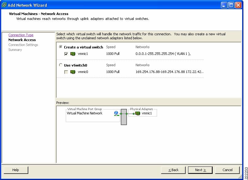
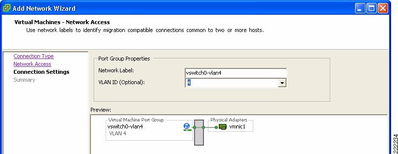
If you choose to create a new vSwitch you can then create the Port Group which is defined by a Network Label, the VLAN number and other characteristics that are analyzed in other sections of this document. In Figure 14 and Figure 15, you can see the creation of vSwitch0 and the definition of a Port Group using VLAN 4 on vSwitch 0. This Port Group uses the Network Label vSwitch0-vlan4.
Figure 15 VLAN Creation from the VirtualCenter GUI
Note ![]() Naming or labeling Port Groups within vSwitches is an important standard to develop and maintain in an ESX environment. You could name the Port Group Network Label after the VLAN, or indicate the vSwitch name and VLAN or simply use the name of the application that attaches to this Port Group.
Naming or labeling Port Groups within vSwitches is an important standard to develop and maintain in an ESX environment. You could name the Port Group Network Label after the VLAN, or indicate the vSwitch name and VLAN or simply use the name of the application that attaches to this Port Group.
Note ![]() In this part of the document, we chose a Network Label name that reflects the vSwitch and the VLAN being used. This may not be the best way of naming Port Groups because the vSwitch name has only local significance and is automatically generated. For VM mobility, the origin Network Label and the destination Network label need to be the same, as well as the VLAN. For this reason you want to use a Network Label name that can be used on a different ESX Server, regardless of which vSwitch the VM migrates to.
In this part of the document, we chose a Network Label name that reflects the vSwitch and the VLAN being used. This may not be the best way of naming Port Groups because the vSwitch name has only local significance and is automatically generated. For VM mobility, the origin Network Label and the destination Network label need to be the same, as well as the VLAN. For this reason you want to use a Network Label name that can be used on a different ESX Server, regardless of which vSwitch the VM migrates to.
Note ![]() Port Groups labels need to be unique across vSwitches on the same ESX host.
Port Groups labels need to be unique across vSwitches on the same ESX host.
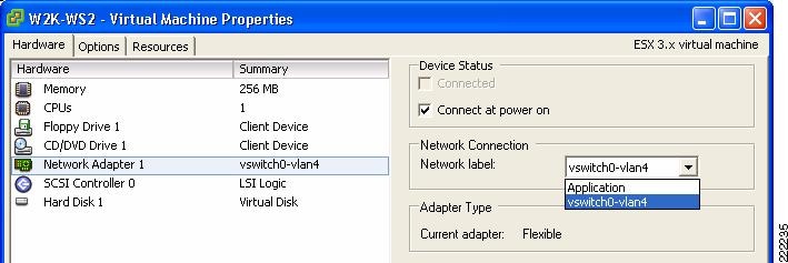
The vNIC of the VM is referred to as Network Adapter in the Edit Settings Window for the VM. The VM Network Adapter configuration (i.e., the vNIC configuration) selects the Port Group within a vSwitch that a VM connects to by referring to its Network Label. By selecting which Port Group a Network Adapter uses, you implicitly assign the VM to a vSwitch, and to a specific VLAN within the vSwitch.
In Figure 16, the Port Group has been labeled after the VLAN that it is used to color the traffic and the vSwitch that this Port Group is defined on.
Figure 16 Joining vNIC and VLAN
A sample configuration is visible from the VMware ESX Server -> Configuration -> Networking tab, as shown in Figure 17. In this example, the VM called W2K-WS2 connects to vSwitch2 on VLAN 100.
Figure 17 vSwitch Final Configuration
Vswitch characteristics can be further modified by selecting the Properties button to the right of the vSwitch. This allows adding more Port Groups, changing the NIC Teaming properties, configure traffic rate limiting, etc.
VMs, VMkernel and Service Console Network Configuration
As shown in Figure 17, vSwitch2 offers network connectivity to multiple VMs (W2K-WS2), to the Service Console, and to the VMkernel.
As a reminder, the Service Console is used by the VirtualCenter or by the Virtual Infrastructure Client to manage the ESX Server, so a change to the Service Console configuration needs to be carefully reviewed to avoid losing management access to the ESX Server. The VMkernel network configuration is used for NAS, iSCSI access and VMotion.
In the Service Console and the VMkernel configurations you can set the IP address, default gateway (which can be, both, different from the Service Console's IP and gateway), VLAN number, and more. These addresses are shown in Figure 17. You can verify the connectivity of the Service Console and the VMkernel by using CLI commands; the ping command for the Service Console and the vmkping command for the VMkernel.
Although it is recommended that Service Console and VMkernel get their own respective dedicated NIC, it is likely that in many deployments they do share vmnics. In this case, it is recommended that, while sharing the same vSwitch, the Service Console be on its own VLAN, the VM Kernel port be on its own VLAN, and the VMs be on VLANs different than the previous two.
With this configuration, the vmnic would be configured for 802.1q trunking as described further later in this document.
vSwitch NIC Teaming Configuration
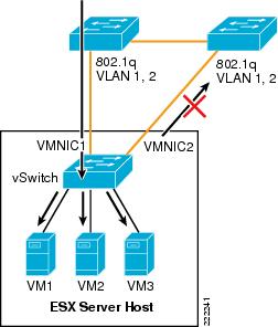
NIC teaming is a vSwitch/vmnic configuration, not a vNIC configuration. In the context of VMware networking NIC teaming refers to configuring the vSwitch uplinks for redundancy. NICs can be attached to different Cisco Catalyst switches or to a single switch, although using separate switches is more common for reasons of redundancy. Figure 18 shows a basic configuration.
Figure 18 Active/Standby NIC Teaming
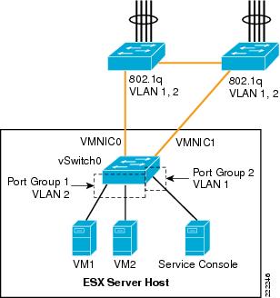
In this example, vSwitch0 is configured with vmnic0 as the active uplink and vmnic1 as the standby uplink. Both links carry VLAN1 and VLAN 2, VLAN1 carries the Service Console traffic, and VLAN 2 carries the VM1 and VM2 traffic.
The configuration of vSwitch0 is accomplished by going to the ESX Host Network Configuration, selecting vSwitch0 Properties, and editing the vSwitch configuration as depicted in Figure 19.
Figure 19 vSwitch NIC Teaming Properties
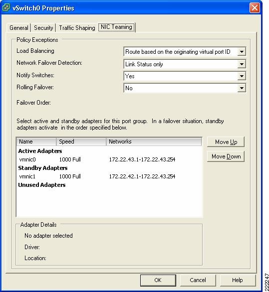
This is a vSwitch-wide configuration:
•![]() This NIC teaming configuration applies to all Port Group/VLANs configured on the vSwitch.
This NIC teaming configuration applies to all Port Group/VLANs configured on the vSwitch.
•![]() The vmnics carry all the VLANs configured.
The vmnics carry all the VLANs configured.
•![]() If the active vmnic (vmnic0) fails, all traffic is assigned to the standby vmnic (vmnic1).
If the active vmnic (vmnic0) fails, all traffic is assigned to the standby vmnic (vmnic1).
•![]() It is possible to override the vSwitch-wide configuration from within each Port Group.
It is possible to override the vSwitch-wide configuration from within each Port Group.
Port Group Configuration
One drawback of an active/standby NIC teaming configuration is that one of the NICs is unused, the standby vmnic1 in the previous example. Although NIC teaming is for the most part a vSwitch-wide configuration, it is also possible to override the global configuration at the Port Group level, thus achieving full NIC utilization with a per-Port Group active/standby configuration.
The following example clarifies. Figure 20 shows a logical view of an ESX Server with one vSwitch configured for teaming. Two ESX Server NICs are connected to the vSwitch as uplinks. VM5 and VM7 connect to vSwitch1 Port Group1 and are configured to use vmnic0 for traffic leaving the vSwitch. Vmnic1 is standby and takes over when vmnic0 fails. VM4 and VM6 connect to vSwitch1 Port Group 2 and use vmnic1 as the preferred uplink. Vmnic0 is standby and takes over when vmnic1 fails.
Note that VM4, VM5, VM6, and VM7 need not be in different VLANs. They can be part of the same VLAN, but simply on two different Port Groups for the purpose of spreading their traffic on two different uplinks.
Note ![]() If VM4, VM5, VM6, and VM7 are on the same VLAN and two different Port Groups, they are in the same broadcast domain.
If VM4, VM5, VM6, and VM7 are on the same VLAN and two different Port Groups, they are in the same broadcast domain.
Figure 20 vSwitch Port Groups NIC Teaming Configuration

Figure 21 shows how VirtualCenter makes this configuration possible. Under the ESX host Configuration, Networking you can select the vSwitch0 properties. Within the "Port tab" select the Port Group of interest (identified by the Network Label, which could be for example the VLAN number), then you can change the Port Group properties which include the NIC Teaming configuration. Figure 21 contrasts the vSwitch properties with the Port Group properties. Note the fact that the Port Group configuration can override the vSwitch-wide configuration and the reverse order of the vmnics in the two configurations.
Figure 21 vSwitch Port Groups NIC Teaming Overrides vSwitch NIC Teaming
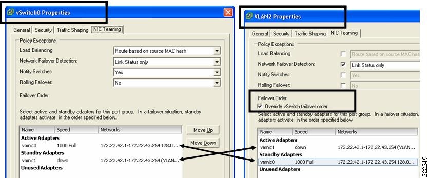
This example shows the following:
•![]() Active/Standby NIC Teaming
Active/Standby NIC Teaming
•![]() The fact that different Port Groups on the same vSwitch can have different teaming/NIC Teaming configurations (also in the case when the VLAN is the same for both Port Groups)
The fact that different Port Groups on the same vSwitch can have different teaming/NIC Teaming configurations (also in the case when the VLAN is the same for both Port Groups)
Changing the NIC Teaming Configuration
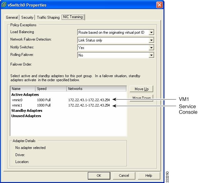
All VMs that share the same NIC teaming policy are part of the same Port Group. From the vSwitch property, select the Port Group of interest (i.e., the Network Label) and the NIC Teaming properties. The load-balancing scrollbar allows choosing the port-based, MAC-based, or IP-based load balancing.
The bigger window lists the available vmnics, which you can move up or down, into the active list, the standby list, or the unused list. This gives you the flexibility of using the same available pool of vmnics from different Port Groups in different ways:
•![]() One Port Group (i.e., one set of VMs) may be using vmnic0 only and keep vmnic1 in standby.
One Port Group (i.e., one set of VMs) may be using vmnic0 only and keep vmnic1 in standby.
•![]() Another Port Group could be using both vmnic0 and vmnic1 with port-based load balancing.
Another Port Group could be using both vmnic0 and vmnic1 with port-based load balancing.
•![]() Yet another Port Group could be using both vmnic0 and vmnic1 in the reversed order to achieve better VM spread over the vmnics.
Yet another Port Group could be using both vmnic0 and vmnic1 in the reversed order to achieve better VM spread over the vmnics.
•![]() A Port Group could be using just vmnic0 and keep vmnic1 in the Unused list (which would isolate VMs when vmnic0 fails).
A Port Group could be using just vmnic0 and keep vmnic1 in the Unused list (which would isolate VMs when vmnic0 fails).
Note ![]() In order to make things simple, you can simply choose an active/active port-based load balancing configuration at the vSwitch level, and leave the other Port Groups NIC teaming configuration untouched.
In order to make things simple, you can simply choose an active/active port-based load balancing configuration at the vSwitch level, and leave the other Port Groups NIC teaming configuration untouched.
Figure 22 vSwitch NIC Teaming Options
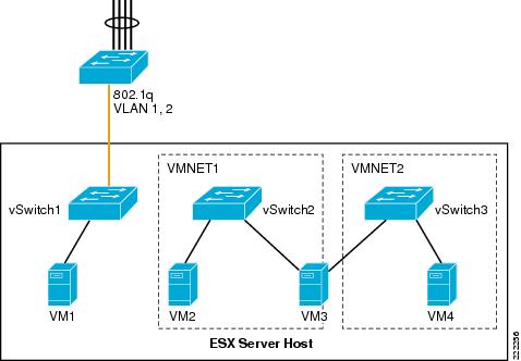
ESX Internal Networking
Internal networks of VMs are sometimes referred to as vmnets or private networks. Internal networks are local to the ESX host without connectivity to the LAN switching environment. Vmnets use the virtual switch to link VMs internally to the ESX Server, and the configuration does not differ especially from the external networking configuration, except, that there is no vmnic assigned to an internal vSwitch. The system bus provides the transport and the CPU manages the traffic. VMnets are generally used in test and development environments.
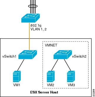
Figure 23 shows a possible, although not very useful, use of internal networking design. In this example, VM2 and VM3 are members of vSwitch2. The Port Groups/VLANs on vSwitch2 are completely internal to the ESX Server. VM2 and VM3 do not communicate with the outside world.
Figure 23 ESX Server Private Virtual Switches
Routing and Bridging
It is possible to create and interconnect multiple private networks by using a VM configured for routing or bridging as it is shown in Figure 24. In Figure 24, VMNET1 (vSwitch2) and VMNET2 (vSwitch3) are interconnected by VM3, which has two vNICs—one per VNET.
Figure 24 ESX Server Private Virtual Switches with Routing or Bridging
Use Case
Private vSwitches can be used for testing purposes but they may also be useful if you need to create a private communication channel among VMs. Figure 25 provides an example (which is not recommended).
In Figure 25, VM4 and VM6 have two vNICs. The public vNIC connects to the outside Cisco LAN switching network via vSwitch0. The private vNIC connects to a private vSwitch (vSwitch1). This allows the two VMs to exchange heartbeat or state information if necessary, locally on the server.
Figure 25 Private vSwitch used for Private Communication Among VMs

The configuration in Figure 25 appears in the VirtualCenter as in the Figure 26.
Figure 26 VirtualCenter View of Private Networks
ESX Server Storage Networking
VMware Infrastructure Storage architecture (see Figure 27) provides a layer of abstraction that hides and manages the complexity of and differences between physical storage subsystems. To the applications and guest operating systems inside each virtual machine, storage is presented simply as SCSI disks connected to a virtual BusLogic or LSI SCSI HBA.
Figure 27 VMware Infrastructure Storage Architecture
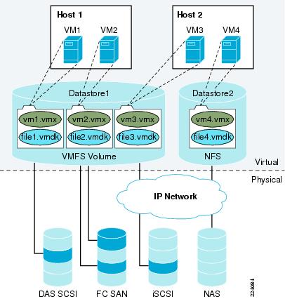
The virtual SCSI disks inside the virtual machines are provisioned from datastore elements in the data center (see Figure 27). A datastore is like a storage appliance that serves up storage space for virtual disks inside the virtual machines, and stores the virtual machine definitions themselves. As shown in Figure 27, a virtual machine is stored as a set of files in its own directory in the datastore.
A virtual disk (vmdk) is a file that resides in a datastore that is managed by ESX. A datastore will reside on a VMFS volume for block-based storage or a mount-point for NFS storage. The VMFS volume is typically comprised of a single LUN, but can span several LUNs. A virtual disk can be easily manipulated (copied, moved, back-up, and so on) just like a file. For guest OS's that support hot-adds of new disks, a new virtual disk can be added without having to shutdown the VM.
The datastore provides a simple model to allocate storage space for the virtual machines without exposing them to the complexity of the variety of physical storage technologies available, such as:
•![]() FibreChannel SAN—The most common deployment option as it enables VMotion, ESX boot from SAN, support for raw device mapping, support high availability clusters (such as Microsoft MSCS). It supports the Virtual Machine File System (VMFS).
FibreChannel SAN—The most common deployment option as it enables VMotion, ESX boot from SAN, support for raw device mapping, support high availability clusters (such as Microsoft MSCS). It supports the Virtual Machine File System (VMFS).
•![]() iSCSI SAN—When associated with hardware-based acceleration, iSCSI SAN enables functions similar to FibreChannel SAN: VMotion migration, ESX boot from SAN, support for raw device mapping. In the case of software-based iSCSI, booting from the SAN is not supported. It supports the VMFS.
iSCSI SAN—When associated with hardware-based acceleration, iSCSI SAN enables functions similar to FibreChannel SAN: VMotion migration, ESX boot from SAN, support for raw device mapping. In the case of software-based iSCSI, booting from the SAN is not supported. It supports the VMFS.
•![]() Direct Attached Storage—Not shared; therefore, not commonly used. Note that ESX Server 3.5 supports VMotion with swap files located on local (DAS) storage.
Direct Attached Storage—Not shared; therefore, not commonly used. Note that ESX Server 3.5 supports VMotion with swap files located on local (DAS) storage.
•![]() NAS—NFS-based storage does not support raw device mapping, nor high availability clusters, it does not use the VMFS, but it allows VMotion migration and booting from NFS.
NAS—NFS-based storage does not support raw device mapping, nor high availability clusters, it does not use the VMFS, but it allows VMotion migration and booting from NFS.
A datastore is physically just a VMFS volume or an NFS-mounted directory. Each datastore can span multiple physical storage subsystems.
As shown in Figure 27, a single VMFS volume can contain one or more smaller volumes from a direct-attached SCSI disk array on a physical server, a FibreChannel SAN disk farm, or iSCSI SAN disk farm. New volumes added to any of the physical storage subsystems or LUNs known to the ESX Server that are expanded within the storage subsystem will be discovered by the ESX Server upon issuing a rescan request through the Virtual Center management interface. They can be added to extend a previously created datastore without powering down physical servers or storage subsystems.
VMware ESX Server Storage Components
This section provides a more detailed technical description of internal ESX Server components and their operation. Figure 28 provides a more detailed view of the ESX Server architecture and specific components that perform VMware storage operations.
Figure 28 Storage Architecture Components
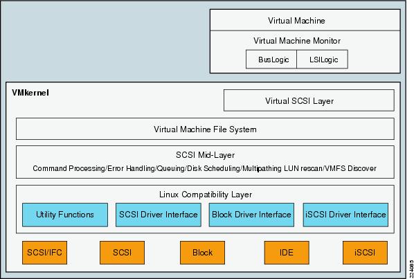
The key components shown in Figure 28 are the following:
•![]() Virtual Machine Monitor (VMM)
Virtual Machine Monitor (VMM)
•![]() Virtual SCSI Layer
Virtual SCSI Layer
•![]() VMFS
VMFS
•![]() SCSI Mid-Layer
SCSI Mid-Layer
•![]() Host Bus Adapter (HBA) Device Drivers
Host Bus Adapter (HBA) Device Drivers
Virtual Machine Monitor (VMM)
The VMM module's primary responsibility is to monitor a virtual machine's activities at all levels (CPU, memory, I/O, and other guest operating system functions and interactions with VMkernel). The VMM module contains a layer that emulates SCSI devices within a virtual machine. A virtual machine operating system does not have direct access to FibreChannel devices because VMware infrastructure virtualizes storage and presents only a SCSI interface to the operating system. Thus, from any type of virtual machine (regardless of operating system), applications only access storage subsystems only via a SCSI driver. Virtual machines can use either BusLogic or LSI Logic SCSI drivers. These SCSI drivers enable the use of virtual SCSI HBAs within a virtual machine.
Note ![]() Within a Windows virtual machine, under the Windows control panel display for Computer Management > Device Manager > SCSI and RAID Controllers, there are listings for BusLogic or LSI Logic drivers. BusLogic indicates that Mylex BusLogic BT-958 emulation is being used. BT-958 is a SCSI-3 protocol providing Ultra SCSI (Fast-40) transfer rates of 40MB per second. The driver emulation supports the capability of "SCSI Configured AutoMatically," also known as SCAM, which allows SCSI devices to be configured with an ID number automatically, so you do not have to assign IDs manually.
Within a Windows virtual machine, under the Windows control panel display for Computer Management > Device Manager > SCSI and RAID Controllers, there are listings for BusLogic or LSI Logic drivers. BusLogic indicates that Mylex BusLogic BT-958 emulation is being used. BT-958 is a SCSI-3 protocol providing Ultra SCSI (Fast-40) transfer rates of 40MB per second. The driver emulation supports the capability of "SCSI Configured AutoMatically," also known as SCAM, which allows SCSI devices to be configured with an ID number automatically, so you do not have to assign IDs manually.
Virtual SCSI HBAs
In an ESX Server environment, each virtual machine includes from one to four virtual SCSI HBAs. Virtual SCSI HBAs allow virtual machines access to logical SCSI devices, just as a physical HBAs allow access to physical storage devices. However, in contrast to a physical HBA, the virtual SCSI HBA does not allow storage administrators (such as SAN administrators) access to the physical machine.
Virtual SCSI Layer
The virtual SCSI layer's primary responsibility is to manage SCSI commands and intercommunication between the VMM, the VMFS, and the SCSI mid-layer below. All SCSI commands from virtual machines must go through the virtual SCSI layer. Also, input/output (I/O) abort and reset operations are managed at this layer. From here, the virtual SCSI layer passes I/O or SCSI commands from virtual machines to lower layers, either via VMFS or device mapping (RDM), which supports two modes: passthrough and non-passthrough. In RDM passthrough mode, all SCSI commands are allowed to pass through without traps.
Virtual Machine File System (VMFS)
VMFS is a clustered file system that leverages shared storage to allow multiple physical servers to read and write to the same storage simultaneously. VMFS provides on-disk distributed locking to ensure that the same virtual machine is not powered on by multiple servers at the same time.
In a simple configuration, the virtual machines' disks are stored as files within a VMFS. When guest operating systems issue SCSI commands to their virtual disks, the virtualization layer translates these commands to VMFS file operations. For details about VMFS, refer to File System Formats.
SCSI Mid-Layer
The SCSI mid-layer is the most important layer in VMkernel for storage activities, managing physical HBAs on ESX Server hosts, queuing requests, and handling SCSI errors. In addition, this layer contains automatic rescan logic that detects changes to LUN mapping assigned to an ESX Server host. Path management such as automatic path selection, path collapsing, failover, and failback to specific volumes are also handled in the SCSI mid-layer.
The SCSI mid-layer gathers information from HBAs, switches, and storage port processors to identify path structures between the ESX Server host and the physical volume on storage arrays. During a rescan, ESX Server looks for device information such as the network address authority (NAA) identifier, and serial number. ESX Server identifies all available paths to a storage array and collapses it to one single active path (regardless of how many paths are available). All other available paths are marked as standby. Path change detection is automatic. Depending on the storage device response to the TEST_UNIT_READY SCSI command, ESX Server marks the path as on, active, standby, or dead.
File System Formats
Datastores that you use can have the following file system formats:
•![]() VMware Virtual Machine File System (VMFS)—ESX Server deploys this type of file system on local SCSI disks, iSCSI volumes, or FibreChannel volumes, creating one directory for each virtual machine.
VMware Virtual Machine File System (VMFS)—ESX Server deploys this type of file system on local SCSI disks, iSCSI volumes, or FibreChannel volumes, creating one directory for each virtual machine.
•![]() Raw Device Mapping (RDM)—RDM allows support of existing file systems on a volume. Instead of using the VMFS-based datastore, virtual machines can have direct access to raw devices using RDM as a proxy.
Raw Device Mapping (RDM)—RDM allows support of existing file systems on a volume. Instead of using the VMFS-based datastore, virtual machines can have direct access to raw devices using RDM as a proxy.
•![]() Network File System (NFS)—ESX Server can use a designated NFS volume located on an NFS server. (ESX Server supports NFS Version 3.) ESX Server mounts the NFS volume, creating one directory for each virtual machine. From the viewpoint of the user on a client computer, the mounted files are indistinguishable from local files.
Network File System (NFS)—ESX Server can use a designated NFS volume located on an NFS server. (ESX Server supports NFS Version 3.) ESX Server mounts the NFS volume, creating one directory for each virtual machine. From the viewpoint of the user on a client computer, the mounted files are indistinguishable from local files.
This document focuses on the first two file system types: VMFS and RDM.
VMFS
VMFS is a clustered file system that leverages shared storage to allow multiple physical servers to read and write to the same storage simultaneously. VMFS provides on-disk distributed locking to ensure that the same virtual machine is not powered on by multiple servers at the same time. If a physical server fails, the on-disk lock for each virtual machine can be released so that virtual machines can be restarted on other physical servers.
A VMFS volume can be extended over 32 physical storage extents, including SAN volumes and local storage. This allows pooling of storage and flexibility in creating the storage volumes necessary for virtual machines. With the new ESX Server 3 LVM, you can extend a volume while virtual machines are running on the volume. This lets you add new space to your VMFS volumes as your virtual machine needs it.
VMFS is first configured as part of the ESX Server installation. Details on VMFS configuration are provided in the VMware Installation and Upgrade Guide as well as the Server Configuration Guide.
Note ![]() ESX Server Version 3 supports only VMFS Version 3 (VMFSv3); if you are using a VMFS-2 datastore, the datastore will be read-only. VMFSv3 is not backward compatible with versions of ESX Server earlier than ESX Server Version 3.
ESX Server Version 3 supports only VMFS Version 3 (VMFSv3); if you are using a VMFS-2 datastore, the datastore will be read-only. VMFSv3 is not backward compatible with versions of ESX Server earlier than ESX Server Version 3.
Users can upgrade VMFS-2 datastores to VMFS-3 in a non-disruptive manner by following the procedure described under "Upgrading Datastores" section in the VI3 SAN System Design and Deployment Guide at the following URL:
http://www.vmware.com/pdf/vi3_san_design_deploy.pdf
For more information on VMFS, refer to the VMware Virtual Machine File System: Technical Overview and Best Practices guide at the following URL:
http://www.vmware.com/pdf/vmfs-best-practices-wp.pdf
The key benefits of using VMFS include:
•![]() VMFS is proprietary to VMware ESX Server and is optimized for storing and accessing large files. The use of large block sizes keeps virtual machine disk performance close to that of native SCSI disks. A simple algorithm provides the formatting on disks. In addition, VMFS-formatted volumes have low overhead; the larger the VMFS disk, the lower the percentage of space used for storing metadata.
VMFS is proprietary to VMware ESX Server and is optimized for storing and accessing large files. The use of large block sizes keeps virtual machine disk performance close to that of native SCSI disks. A simple algorithm provides the formatting on disks. In addition, VMFS-formatted volumes have low overhead; the larger the VMFS disk, the lower the percentage of space used for storing metadata.
•![]() It has built-in logic for rescan that detects changes in LUNs automatically.
It has built-in logic for rescan that detects changes in LUNs automatically.
•![]() VMFS also features enterprise-class crash consistency and recovery mechanisms, such as distributed journaling, crash-consistent virtual machine I/O paths, and machine state snapshots. These mechanisms can aide quick root-cause analysis and recovery from virtual machine, physical server, and storage subsystem failures.
VMFS also features enterprise-class crash consistency and recovery mechanisms, such as distributed journaling, crash-consistent virtual machine I/O paths, and machine state snapshots. These mechanisms can aide quick root-cause analysis and recovery from virtual machine, physical server, and storage subsystem failures.
Raw Device Mapping
VMFS also supports RDM, which provides a mechanism for a virtual machine to have direct access to a volume on the physical storage subsystem (with FibreChannel or iSCSI only). This is used for applications such as high availability clusters running on the Guest OS or SAN-based backups.
An RDM can be thought of as providing a symbolic link from a VMFS volume to a raw volume (see Figure 29). The mapping makes volumes appear as files in a VMFS volume. The mapping file—not the raw volume—is referenced in the virtual machine configuration.
Figure 29 VMware Raw Device Mapping
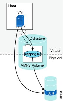
When a volume is opened for access, VMFS resolves the RDM file to the correct physical device and performs appropriate access checking and locking before accessing the volume. Thereafter, reads and writes go directly to the raw volume rather than going through the mapping file.
RDM files contain metadata used to manage and redirect disk accesses to the physical device. RDM provides the advantages of direct access to a physical device while keeping some advantages of a virtual disk in the VMFS. In effect, it merges VMFS manageability with raw device access. See Figure 30.
Figure 30 Raw Device Mapping Redirects Data Transfers
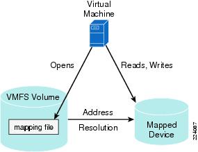
Using RDMs, you can:
•![]() Use VMotion to migrate virtual machines using raw volumes.
Use VMotion to migrate virtual machines using raw volumes.
•![]() Add raw volumes to virtual machines using the virtual infrastructure client.
Add raw volumes to virtual machines using the virtual infrastructure client.
•![]() Use file system features such as distributed file locking, permissions, and naming.
Use file system features such as distributed file locking, permissions, and naming.
Two compatibility modes are available for RDMs:
•![]() Physical compatibility—Allows the guest operating system to access the hardware directly. Physical compatibility is useful if you are using SAN aware applications in the virtual machine. However, a virtual machine with the physical compatibility RDM cannot be cloned, made into a template, or migrated if the migration involves copying the disk.
Physical compatibility—Allows the guest operating system to access the hardware directly. Physical compatibility is useful if you are using SAN aware applications in the virtual machine. However, a virtual machine with the physical compatibility RDM cannot be cloned, made into a template, or migrated if the migration involves copying the disk.
•![]() Virtual compatibility—Allows the RDM to behave as if it were a virtual disk, so you can use such features as snapshotting, cloning, and so on. Depending on your choice, subsequent screens offer different options.
Virtual compatibility—Allows the RDM to behave as if it were a virtual disk, so you can use such features as snapshotting, cloning, and so on. Depending on your choice, subsequent screens offer different options.
Note ![]() VMware VMotion, VMware Dynamic Resource Scheduler, and VMware HA are all supported in both RDM physical and virtual compatibility modes.
VMware VMotion, VMware Dynamic Resource Scheduler, and VMware HA are all supported in both RDM physical and virtual compatibility modes.
While VMFS is recommended for most virtual disk storage, sometimes you need raw disks. The most common use is as data drives for Microsoft Cluster Service (MSCS) configurations using clusters between virtual machines or between physical and virtual machines. Cluster data and quorum disks should be configured as RDMs rather than as individual files on a shared VMFS.
Note ![]() For more information on MSCS configurations supported with VMware infrastructure, refer to the VMware Setup for Microsoft Cluster Service documentation available at the following URL: http://www.vmware.com/support/pubs
For more information on MSCS configurations supported with VMware infrastructure, refer to the VMware Setup for Microsoft Cluster Service documentation available at the following URL: http://www.vmware.com/support/pubs
Multipathing and Path Failover
A FibreChannel path describes a route as follows:
1. ![]() From a specific HBA port in the host
From a specific HBA port in the host
2. ![]() Through the switches in the fabric
Through the switches in the fabric
3. ![]() Into a specific storage port on the storage array
Into a specific storage port on the storage array
A given host might be able to access a volume on a storage array through more than one path. Having more than one path from a host to a volume is called multipathing.
By default, VMware ESX Server systems use only one path from the host to a given volume at any time. If the path actively being used by the VMware ESX Server system fails, the server selects another of the available paths. The process of detecting a failed path by the built-in ESX Server multipathing mechanism and switching to another path is called path failover. A path fails if any of the components along the path fails, which may include the HBA, cable, switch port, or storage processor. This method of server-based multipathing may take up to a minute to complete, depending on the recovery mechanism used by the SAN components (that is, the SAN array hardware components).
ESX multipathing has two main operation modes:
•![]() Fixed—User specifies a preferred path. If that path is lost, a secondary one is used. Once the primary path comes back, traffic is switched again to the primary path.
Fixed—User specifies a preferred path. If that path is lost, a secondary one is used. Once the primary path comes back, traffic is switched again to the primary path.
•![]() Most Recently Used (MRU)—If the current path fails, ESX selects a secondary path. Once the previous path reappears, the traffic is still switched along the secondary path.
Most Recently Used (MRU)—If the current path fails, ESX selects a secondary path. Once the previous path reappears, the traffic is still switched along the secondary path.
Active/Active and Active/Passive Disk Arrays
It is useful to distinguish between active/active and active/passive disk arrays:
•![]() An active/active disk array allows access to the volumes simultaneously through all the storage paths that are available without significant performance degradation. All the paths are active at all times (unless a path fails).
An active/active disk array allows access to the volumes simultaneously through all the storage paths that are available without significant performance degradation. All the paths are active at all times (unless a path fails).
•![]() In an active/passive disk array, one storage path is actively servicing a given volume. The other storage path acts as backup for the volume and may be actively servicing other volume I/O. I/O can be sent only to an active processor. If the primary storage processor fails, one of the secondary storage processors becomes active, either automatically or through administrator intervention.
In an active/passive disk array, one storage path is actively servicing a given volume. The other storage path acts as backup for the volume and may be actively servicing other volume I/O. I/O can be sent only to an active processor. If the primary storage processor fails, one of the secondary storage processors becomes active, either automatically or through administrator intervention.
In Figure 31, one storage processor is active while the other is passive. Data arrives through the active array only.
Figure 31 Active/Passive Storage Array
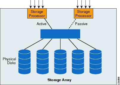
Path Failure Detection
During boot up or a rescan operation, ESX Server automatically assigns a path policy of fixed for all active/active storage array types. With a fixed path policy, the preferred path is selected if that path is in the ON state.
ESX Server multipathing software does not actively signal virtual machines to abort I/O requests. If the multipathing mechanism detects that the current path is no longer operational, ESX Server initiates a process to activate another path to the volume and reissues the virtual machine I/O request to the new path (instead of immediately returning the I/O failure to the virtual machine).
For active/active storage array types, ESX Server performs a path failover only if a SCSI I/O request fails with a FC driver status of NO_CONNECT, which indicates a loss of FC connectivity. Commands that fail with check conditions are returned to the guest operating system. When a path failover is completed, ESX Server issues the command to the next path that is in the on state.
For active/passive storage array types, ESX Server automatically assigns a path policy of most recently used (MRU). A device response to TEST_UNIT_READY of NO_CONNECT and specific SCSI check conditions triggers ESX Server to test all available paths to see if they are in the ON state.
Note ![]() For active/passive storage arrays that are not on the VMware SAN Compatibility list, manually changing an active/passive array to use the MRU policy is not sufficient to make the array be fully interoperable with ESX Server. Any new storage arrays must be approved by VMware and be listed in the VMware SAN Compatibility Guide.
For active/passive storage arrays that are not on the VMware SAN Compatibility list, manually changing an active/passive array to use the MRU policy is not sufficient to make the array be fully interoperable with ESX Server. Any new storage arrays must be approved by VMware and be listed in the VMware SAN Compatibility Guide.
ESX Server Connectivity and Networking Design Considerations
LAN Connectivity
The Cisco data center architecture provides scalability, availability, and network services to enterprise server farms. Figure 32 shows the Cisco data center network design.
Figure 32 Cisco Data Center Architecture
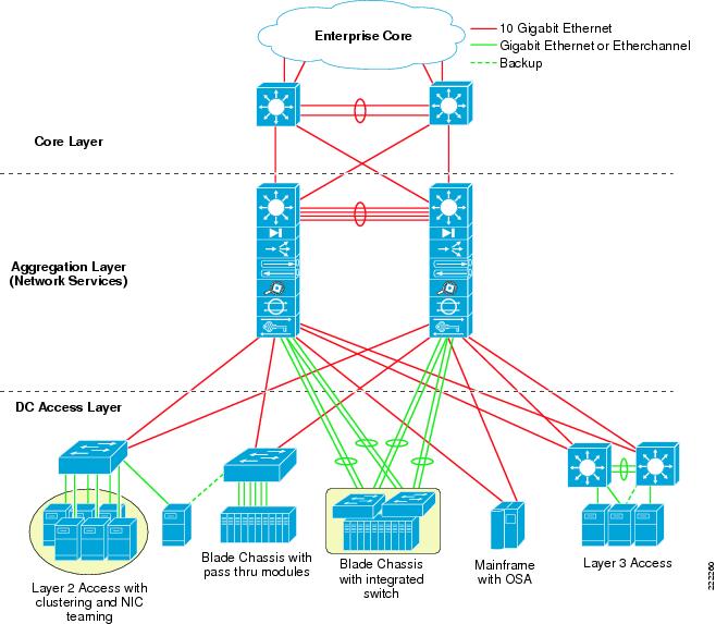
The design comprises three major functional layers (core, aggregation, and access), and provides the following:
•![]() Support for Layer 2/3 requirements (high availability via HSRP, STP)
Support for Layer 2/3 requirements (high availability via HSRP, STP)
•![]() High performance multi-layer switching
High performance multi-layer switching
•![]() Multiple uplink options
Multiple uplink options
•![]() Consolidated physical infrastructure
Consolidated physical infrastructure
•![]() Network services (security, load balancing, application optimization)
Network services (security, load balancing, application optimization)
•![]() Scalable modular design
Scalable modular design
For more information and details on the Cisco Data Center Network, see the following URL: http://www.cisco.com/go/datacenter/
Preliminary Design Considerations
Connecting an ESX Server to the LAN infrastructure is an exercise that mainly involves designing vSwitches connectivity to the LAN infrastructure. The forwarding behavior of the vSwitch needs to be considered, and if not understood it is recommended that you design the LAN switching infrastructure as you would in presence of a server with active/standby NIC Teaming or Port-Channeling (depending on the ESX host configuration).
Another important aspect of the design is the network management of the ESX host via the Service Console and VMkernel. The configuration needs to provide both performance and high availability in case of network link failures. ESX host networking configurations combined with the Cisco LAN switching technology provide both.
vSwitch Comparison with a LAN switch
The preceding sections described how a vSwitch differs from a regular LAN switch. These characteristics are listed in ESX Virtual Switch. The following is a list of the most significant behaviors of the vSwitch:
•![]() Traffic generated by the VMs with a destination MAC address of a VM is sent to the local VM. Everything else is sent to the vmnics.
Traffic generated by the VMs with a destination MAC address of a VM is sent to the local VM. Everything else is sent to the vmnics.
•![]() If traffic coming from the LAN switching infrastructure has a destination MAC address of the VMs is sent to the VMs, otherwise it is dropped.
If traffic coming from the LAN switching infrastructure has a destination MAC address of the VMs is sent to the VMs, otherwise it is dropped.
•![]() External broadcast and multicast traffic is flooded to the VMs, but not to the other vmnics.
External broadcast and multicast traffic is flooded to the VMs, but not to the other vmnics.
•![]() VM generated Broadcast and Multicast traffic is sent out of a single vmnic.
VM generated Broadcast and Multicast traffic is sent out of a single vmnic.
•![]() Traffic from VM-to-VM within the same vSwitch and VLAN remains local.
Traffic from VM-to-VM within the same vSwitch and VLAN remains local.
•![]() vSwitches are capable of trunking (802.1q trunks without negotiation protocols).
vSwitches are capable of trunking (802.1q trunks without negotiation protocols).
•![]() vSwitches color traffic from the VM with the VLAN ID specified in the Port Group configuration.
vSwitches color traffic from the VM with the VLAN ID specified in the Port Group configuration.
VLAN Provisioning
The network design for vSwitches connected to the LAN in a redundant fashion should always ensure a Layer 2 path from one vSwitch NIC to other vSwitches that are in the same Layer 2 domain. This Layer 2 path needs to be provided by the Cisco LAN network and cannot be provided by vSwitches themselves.
Although vSwitches for the most part look like a LAN switch, certain forwarding characteristics and the specific techniques used for loop avoidance, make certain designs possible and others not.
If you do not know what is inside the ESX Server in terms of vSwitches and VMs, you should design LAN connectivity as if it were a regular server with NIC teaming. You should assume that it requires Layer 2 adjacency between two NICs. The example in Figure 33 shows why. From a Layer 2 design point of view, Figure 33 shows a "looped" topology, which means that there are redundant Layer 2 paths to every destination. vSwitches keep the topology free from loops with VMware-specific mechanisms that are partially related to distance vector technology such as avoiding to forward traffic back to the NICs it was received from. Traffic from the VMs is load balanced to both vmnics based on the NIC teaming load-balancing algorithms previously described.
Figure 33 VLAN Design
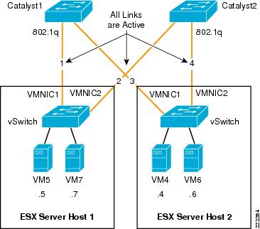
If you consider the network created by vSwitches and the Cisco Catalyst switches, in this topology everything is Layer 2 adjacent. All links are 802.1q trunks that carry the VMs' VLANs. For the purpose of this example, all VMs are in the same VLAN.
You may be surprised to find out that VM5 can talk to VM7, but cannot talk to VM4. Imagine that VM5 and VM7 both hash to vmnic1, while VM4 and VM6 both hash to vmnic2. Catalyst1 learns VM5 and VM7's MAC address on link1, Catalyst2 learns VM4 and VM6's MAC address on link4.
When VM5 sends traffic to VM4, Catalyst 1 would then have to flood the traffic destined from VM5 to VM4 out of link3. The vSwitch in ESX Server Host 2, would not take this traffic as a loop prevention mechanism: it expects to see the traffic destined to VM4 to come in from link4. In order to solve this problem, all you need to do is connect Catalyst1 to Catalyst2 with a Layer 2 link trunking the VM's VLANs.
The VLAN design depicted in Figure 37 shows a portion of an overall LAN switching topology (the U-shape which is explained later) that fixes the problem. In Figure 34 the network administrator has provisioned Layer 2 adjacency between the NIC cards via the Cisco Catalyst switches.
As a summary, when designing a network that supports VMware, make sure to provision a Layer 2 redundant path that does not rely on the vSwitch for VMs of different vSwitches to communicate with each other.
Figure 34 VLAN Design that Ensures VMs Connectivity
Traffic Load Balancing
One common requirement when designing network connectivity is to use all the available links from the server to the network. Some NIC teaming configuration allow this intrinsically:
•![]() Active/active with load balancing based upon the hash of the MAC address.
Active/active with load balancing based upon the hash of the MAC address.
•![]() Active/active with load balancing based upon the hash of the originating virtual port ID (recommended option).
Active/active with load balancing based upon the hash of the originating virtual port ID (recommended option).
•![]() EtherChanneling.
EtherChanneling.
Both were described in previous sections of this document. In addition to these mechanisms, it is also possible to achieve outgoing and incoming traffic load balancing by using active/standby as described in this section. VMs are divided into two groups, one belongs to Port Group 1, and one belongs to Port Group 2. Both Port Groups use the same vSwitch, but Port Group 1 uses vmnic0 as the main NIC and vmnic1 as the standby NIC, and Port Group 2 uses vmnic1 as the main NIC and vmnic0 as the standby NIC. Figure 35 illustrates the configuration.
Figure 35 ESX Server Redundant Configuration with Traffic Load Balancing
The advantage of this design is that the network administrator knows that at any given time if no failure occurs, VM5 and VM7 use vmnic0 and VM4 and VM6 use vmnic1.
Note ![]() Realize that for traffic load balancing from the vSwitch to the Cisco LAN switching infrastructure you do not need to have two set of VLANs. In other words VM4, VM5, VM6, VM7 can all be on the same VLAN. All that is required is to split them on two different Port Groups. Splitting the VMs in two Port Groups does not affect the ability of VM5 and VM7 to communicate with VM4 and VM6.
Realize that for traffic load balancing from the vSwitch to the Cisco LAN switching infrastructure you do not need to have two set of VLANs. In other words VM4, VM5, VM6, VM7 can all be on the same VLAN. All that is required is to split them on two different Port Groups. Splitting the VMs in two Port Groups does not affect the ability of VM5 and VM7 to communicate with VM4 and VM6.
Note ![]() This design is an interesting option to consider when provisioning Service Console and VMkernel connectivity; in that with two NICs, you can give the full bandwidth of one NIC to Service Console + VMkernel and the full bandwidth of the other NIC to VMs, while still providing redundancy. If either NIC fails, the remaining one provides connectivity for all the Port Groups: Service Console, VMkernel, and VMs.
This design is an interesting option to consider when provisioning Service Console and VMkernel connectivity; in that with two NICs, you can give the full bandwidth of one NIC to Service Console + VMkernel and the full bandwidth of the other NIC to VMs, while still providing redundancy. If either NIC fails, the remaining one provides connectivity for all the Port Groups: Service Console, VMkernel, and VMs.
VMware Management Interface Assignment
Given the limited number of NIC cards available on many server platforms (most notably on blade servers) and the need for providing redundant paths to Service Console and VMkernel, it is necessary to configure ESX hosts on a server platform such that management traffic shares NICs with production traffic.
Note ![]() Depending on the blade server vendor, only two or three Ethernet adapters may be available. Therefore, ESX supports blade server deployments through the sharing of physical resources via 802.1q trunks.
Depending on the blade server vendor, only two or three Ethernet adapters may be available. Therefore, ESX supports blade server deployments through the sharing of physical resources via 802.1q trunks.
Figure 36 shows an example network configuration where vmnic1 and vmnic2 are shared by the Service Console Port Group, VMkernel Port Group, and the production traffic.
Figure 36 Sharing Adapter Resources
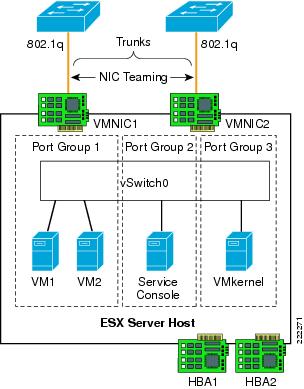
The virtual switch supports VMotion transport in addition to the traffic originating from the VMs. Service Console and VMkernel are configured in separate Port Groups than the VMs, each one with their respective VLAN. The VM VLAN, Service Console VLAN, and VMkernel VLANs share the ESX Server NIC ports.
Sharing network resources may affect the performance of all traffic types because competition for a finite resource may occur. For example, the VMotion process may take longer to complete when interfaces are allocated for production and management traffic.
vSwitch Configuration Guidelines
The following guidelines apply to configuring the vSwitch in the ESX host:
•![]() There is no need to create multiple vSwitches to segment VM traffic or Service Console/ VMkernel traffic, just use Port Groups with different VLAN IDs and override the global teaming configuration to implement Port Group specific traffic load balancing.
There is no need to create multiple vSwitches to segment VM traffic or Service Console/ VMkernel traffic, just use Port Groups with different VLAN IDs and override the global teaming configuration to implement Port Group specific traffic load balancing.
•![]() The preferred 802.1q VLAN tagging mechanism is VST (i.e., assigning a specific VLAN ID to a Port Group).
The preferred 802.1q VLAN tagging mechanism is VST (i.e., assigning a specific VLAN ID to a Port Group).
•![]() Avoid using the native VLAN as an explicit VLAN ID; if you need to use the native VLAN, specify VLAN ID = 0 to the relevant Port Group.
Avoid using the native VLAN as an explicit VLAN ID; if you need to use the native VLAN, specify VLAN ID = 0 to the relevant Port Group.
•![]() The preferred traffic load balancing mechanism is active/active virtual Port-ID-based.
The preferred traffic load balancing mechanism is active/active virtual Port-ID-based.
•![]() If possible, create NIC teaming configurations across different NIC chipsets.
If possible, create NIC teaming configurations across different NIC chipsets.
•![]() Beaconing is not recommended.
Beaconing is not recommended.
•![]() Failback = Yes (ESX 3.5) or Rolling Failover = No (ESX 3.0.x) is recommended only if there is no likelihood of blackholing traffic. This should be used in conjunction with trunkfast on aggregation switches and/or link state tracking. See Teaming Failback.
Failback = Yes (ESX 3.5) or Rolling Failover = No (ESX 3.0.x) is recommended only if there is no likelihood of blackholing traffic. This should be used in conjunction with trunkfast on aggregation switches and/or link state tracking. See Teaming Failback.
Access Port Configuration Guidelines
Within the context of this document, the term access port refers to the port connecting to the ESX Server NIC card. This port can be a switchport access type of configuration as well as a switchport trunk configuration, and most of the time it is in fact a switchport trunk, because internally ESX Servers use multiple VLANs.
The most common ESX Server design consists of using the Virtual Switch Tagging (VST) configuration, which requires the Cisco LAN switch port to be configured as a trunk.
Due to the specifics of VMware, the following design considerations apply:
•![]() Configure the switchport trunk for trunkfast (i.e., such that the port goes forwarding immediately without waiting for Spanning Tree timers).
Configure the switchport trunk for trunkfast (i.e., such that the port goes forwarding immediately without waiting for Spanning Tree timers).
•![]() On ESX, the native VLAN of a switchport is always tagged, unless you configure the VM Port Group that uses the native VLAN with VLAN ID = 0 (EST). For simplicity of configuration and to avoid traffic isolation, make sure no VM uses the native VLAN. If you still want to use the native VLAN in a VST configuration configure, the Cisco LAN switch for native VLAN tagging is enabled with the vlan dot1q tag native command. If you use a VM Port Group in EST mode (VLAN ID = 0), no special configuration is required on the Cisco Catalyst switch (i.e., the no vlan dot1q tag native command is enabled).
On ESX, the native VLAN of a switchport is always tagged, unless you configure the VM Port Group that uses the native VLAN with VLAN ID = 0 (EST). For simplicity of configuration and to avoid traffic isolation, make sure no VM uses the native VLAN. If you still want to use the native VLAN in a VST configuration configure, the Cisco LAN switch for native VLAN tagging is enabled with the vlan dot1q tag native command. If you use a VM Port Group in EST mode (VLAN ID = 0), no special configuration is required on the Cisco Catalyst switch (i.e., the no vlan dot1q tag native command is enabled).
•![]() Port-security is not recommended due to the need for the VM MAC addresses to move from one switchport to a different switchport on the same or a different switch and on the same VLAN without the port physically going down.
Port-security is not recommended due to the need for the VM MAC addresses to move from one switchport to a different switchport on the same or a different switch and on the same VLAN without the port physically going down.
Port Configuration with Virtual Switch Tagging
VST permits the vSwitch to tag all egress traffic and conversely to remove the tags from all ingress traffic. VST mode require the use of 802.1q trunks. The switchport configuration that follows sets the encapsulation to 802.1q, it specifies the native VLAN, the allowed VLANs, the mode to be trunk (instead of access), and the fact that the Dynamic Trunking Negotiation Protocol (DTP) is not enabled. It also specifies that the port should go into forwarding mode immediately upon link up.
Note that Cisco Discovery Protocol (CDP) is supported on ESX and provides administrators visibility into what physical switch ports are connected to the vSwitch vmnics.
spanning-tree portfast bpduguard default
!
interface GigabitEthernetX/X
description <<** VM Port **>>
no ip address
switchport
switchport trunk encapsulation dot1q
switchport trunk native vlan <id>
switchport trunk allowed vlan xx,yy-zz
switchport mode trunk
switchport nonegotiate
no cdp enable
spanning-tree portfast trunk
!
ESX Hosts with Two NICs
Active/Active all NICs Shared
The simplest design with VMware consists in spreading the physical NICs of the ESX Server to two access layer switches, and splitting the NICs for Service Console and VMkernel; and sharing the NICs for Guest VM production traffic. With this design, NICs are part of an ESX NIC teaming configuration. Figure 37 illustrates the design. With this design, VMs share the two vmnics with active/active VM Port-ID-based load balancing. The 802.1q VLAN assignment scheme chosen is VST. The Service Console Port Group is on its own VLAN and would be configured to use vmnic1 and, should vmnic1 fail, use vmnic2. Similarly, the VMkernel Port Group has its own VLAN and would be configured to use vmnic2 and should vmnic2 fail, use vmnic1.
By following this approach, all vmnics are used, connectivity is fully redundant, and the management traffic is spread on the two upstream vmnics. Note that the Port Group teaming configuration for the Service Console and the VMkernel override the global vSwitch NIC teaming configuration.
The main advantage of this design is that the production traffic is spread on both upstream vmnics. The main disadvantage is that VMotion migration may slow down due to the traffic sharing with production traffic.
The ESX Server in this design is dual-homed to the access layer switches. Configuring the physical switch ports as 802.1q trunks enables traffic forwarding for VMs that may be on different VLANs on the vSwitch. Configuring these ports as edge ports (trunkfast) in relation to Spanning Tree accelerates network convergence when failure conditions occur. The VMotion process uses the same physical infrastructure virtualized through VLANs to allow active VM migrations.
Figure 37 ESX Server vSwitch Design with Active/Active NIC Teaming
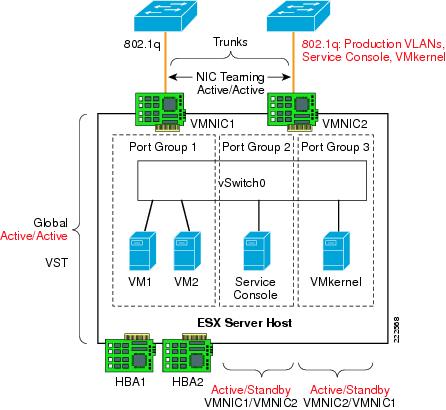
Redundant Dedicated NICs for Production and for VMkernel/Service Console
If ensuring enough bandwidth for the VMkernel is a concern, you can deploy a slightly different design than the one describes in the previous section. The alternative design is illustrated in Figure 38. In this design the VMs all use vmnic1 as the active NIC and vmnic2 as the standby NIC. At the same time Service Console and VMkernel Port Groups use vmnic1 as the active NIC and vmnic2 as the standby NIC. By following this approach, enough bandwidth for VMotion is always available to the VMkernel and should vmnic2 fail, vmnic1 can accommodate both production and VMkernel traffic. Just like in the previous design, the vSwitch assigns VLANs to Service Console traffic, VMkernel traffic, and VMs traffic with the VST approach.
The main advantage of this design is that the VMkernel traffic has its own vmnics and there is no production traffic on this vmnic. Production traffic uses only one upstream vmnic.
Figure 38 Dedicated Active NIC for VMkernel and Service Console
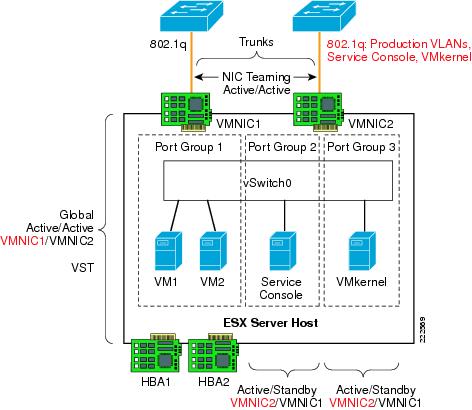
The ESX Server in this design is dual-homed to the access layer switches. Configuring the access ports as 802.1q trunks enables traffic forwarding for VMs that may be on different VLANs on the vSwitch. Configuring these ports as edge ports (trunkfast) in relation to Spanning Tree accelerates network convergence when failure conditions occur. The VMotion process uses the same physical infrastructure virtualized through VLANs to allow active VM migrations.
Access Layer Connectivity with Classic Access Layer Design
Both of the designs previously described (see Figure 37 and Figure 38) can be attached to a Cisco LAN switching infrastructure in the possible design flavors depicted in Figure 39: the loop free U-shape design (which has no Spanning Tree blocking ports) and the V-shape design (which has one forwarding link per access switch, and the redundant link or links in blocking mode).
In order to further clarify the designs, consider Figure 40. In this diagram, you can see how the U-shape access switches Catalyst1 and Catalyst2 connect to each other and to the aggregation layer. The direct link connecting the two access switches provides the Layer 2 adjacency required by the vmnics.
Rapid PVST+ provides fast Spanning Tree convergence, even if no port is in blocking state. The ESX hosts do not run Spanning Tree and connect in redundant fashion to both access switches. All the access layer switches ports connecting to the ESX host are trunks and are configured to carry the Service Console VLAN, the VMkernel VLAN, and the VM production VLANs.
Figure 39 ESX Server Correct VLAN Designs
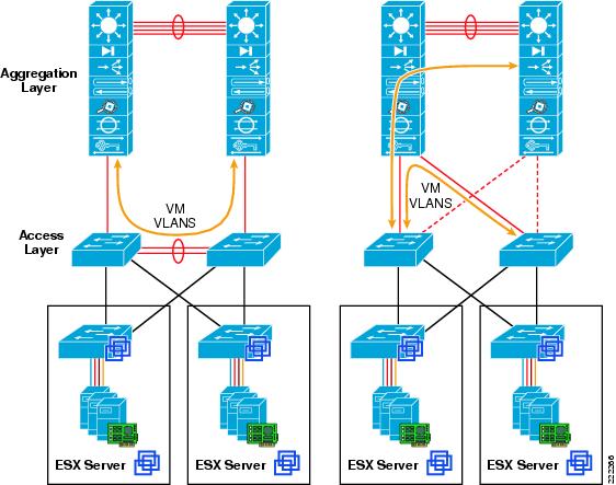
Figure 40 ESX Server with Cisco Switches U-shape Design
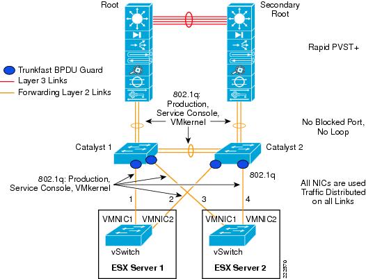
Figure 41 illustrates the design with the use of the Cisco V-shape LAN switching topology. The access switches Catalyst1 and Catalyst2 are dual-connected to the aggregation layer switches. The aggregation layer provides the root and secondary root function. Of the two set of links from the access layer, the one connecting to the secondary root is in Spanning Tree blocking state.
As with the previous design, the access ports connecting to the ESX hosts are configured as 802.1q trunks carrying the Service Console VLAN, the VMkernel VLAN, and the VM production VLANs.
Figure 41 ESX Server with Cisco Switches V-shape Design
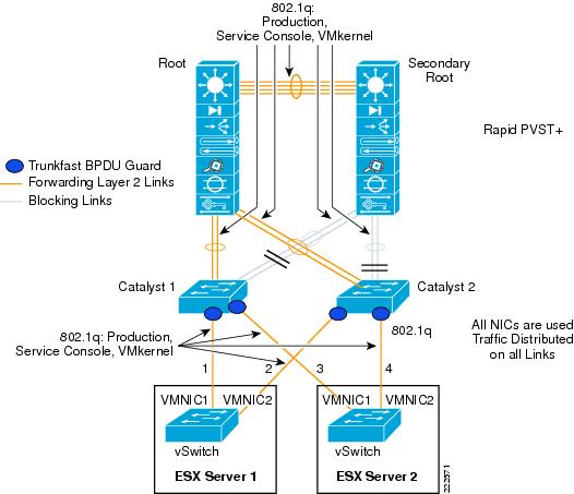
Access Layer Connectivity with EtherChannel
An alternative design consists in connecting both vmnics from a vSwitch to the Cisco Catalyst switch with an EtherChannel. This EtherChannel would, in turn, trunk all the VLANs: VM production VLANs, Service Console VLAN, and VMkernel VLAN.
Three options exist on the Catalyst switch side:
•![]() Using a single switch with dual supervisors capable of stateful switchover (SSO)
Using a single switch with dual supervisors capable of stateful switchover (SSO)
•![]() Using Cisco Catalyst 6500 Virtual Switching System (VSS) configured to virtualize (cluster) two Catalyst systems to look like a single switch
Using Cisco Catalyst 6500 Virtual Switching System (VSS) configured to virtualize (cluster) two Catalyst systems to look like a single switch
•![]() Using Cisco Blade Switches (CBS) in Virtual Blade Switch (VBS) mode configured to virtualize (cluster) up to 8 blade switches to look like a single switch.
Using Cisco Blade Switches (CBS) in Virtual Blade Switch (VBS) mode configured to virtualize (cluster) up to 8 blade switches to look like a single switch.
•![]() Using Catalyst 3750 with Cross Stack Etherchannel to virtualize up to eight switches as a single logical switch.
Using Catalyst 3750 with Cross Stack Etherchannel to virtualize up to eight switches as a single logical switch.
SSO provides Layer 2 high availability using redundant supervisors in an active/standby scenario, introducing approximately 0 to 3 seconds of packet loss when a supervisor switchover occurs. Attaching the ESX Server to a single access layer switch with supervisor redundancy may be an acceptable level of redundancy for some enterprises.
Aggregating the ESX Server links to the access layer switch allows for increased utilization of server resources. The ESX administrator may configure the team to load balance egress traffic on the source and destination IP address information. This algorithm may improve the overall link use of the ESX system by providing a more balanced distribution across the aggregated links.
The 802.3ad links remove a single point of failure from the server uplink perspective, which reduces the chances that VM traffic will be black-holed. On the other hand, if the upstream switch becomes unavailable the ESX host is isolated both from a management perspective as well as for the production VLANs.
It is also possible to use an aggregated link EtherChannel configuration with stackable switches, such as the Cisco 3750 platform. A switch stack is logically a single switch that allows the use of aggregated ports and src/dst IP load balancing equivalent to the single switch access design.
An example of configuration for two Cisco switch access ports configured to channel to vmnic0 and vmnic1 looks like as follows:
interface GigabitEthernet1/0/14
description Link to ESX vmnic0
switchport trunk encapsulation dot1q
switchport trunk allowed vlan 55,100,200,511
switchport mode trunk
switchport nonegotiate
no mdix auto
channel-group 5 mode on
spanning-tree portfast trunk
end
!
interface GigabitEthernet2/0/14
description to_ESX_vmnic1
switchport trunk encapsulation dot1q
switchport trunk allowed vlan 55,100,200,511
switchport mode trunk
switchport nonegotiate
no mdix auto
channel-group 5 mode on
spanning-tree portfast trunk
end
Note the configuration channel-group <number> mode on command, which forces the ports into forming an EtherChannel without negotiating with LACP.
Figure 42 shows the topology with the clustered access switches where channels are configured with one port on switch1 (GigabitEthernet1/0/x) and one on switch2 (GigabitEthernet2/0/x). All links to the access switches are configured as 802.1q trunks carrying VM Production VLANs, Service Console traffic as well as VMkernel traffic.
Figure 42 ESX Server EtherChannel with Cisco Clustered Switches

The aggregation switches connect the access switches with EtherChannels, and one EtherChannel (the one to the secondary root) is in blocking mode from a Spanning Tree prespective.
ESX Hosts with Four NICs
An ESX host with four NICs offers more connectivity options than an ESX host with two NICs. It may be tempting to assign one dedicated NIC for the Service Console, one for the VMkernel and the remaining, two for VM production traffic. Such a configuration is good but can be optimized.
In fact a non-redundant Service Console configuration may isolate the ESX host from management, and in case VMware HA is used, cause the VMs to be powered down on the affected ESX host and started up on a different one, which is undesirable since the ESX host may still be connected to the VM production network.
Similarly, a single NIC dedicated to the VMkernel with no redundancy may cause problems from which is very difficult to recover if you are using iSCSI or make a VM VMotion migration impossible.
Configuration Optimized for Redundancy
The configuration described in this section provides no single point of failure which could isolate the management or cause VMware HA false alarms. This configuration also provides fault tolerance against chipset problems by teaming NIC cards across different chipsets. Figure 43 shows such configuration.
The VM Port Groups are connected to both vmnic1 and vmnic3 which exist on different chipset. The two vmnics are configured for active/active virtual Port-ID-based load balancing. The Service Console Port Group is configured to use vmnic2 as the active vmnic, and vmnic4 as the standby. The VMkernel Port Group is configured to use vmnic4 as the active NIC and vmnic2 as the standby.
Figure 43 ESX Server with 4 NICs and a Fully Redundant Configuration

With this configuration, the Catalyst switch access ports connected to vmnic1 and vmnic3 need to be configured for 802.1q trunking of the VM production VLANs. The Catalyst switch access ports connecting to vmnic2 and vmnic4 need to be configured for 802.1q trunking of the Service Console and VMkernel VLAN.
For server architecture performance reasons, it may be preferred to provide traffic load balancing in a NIC teaming configuration from a single NIC chipset. If this is a concern, the configuration in Figure 43 can be modified as shown in Figure 44. In this case, one chipset of two NICs is used by VM production traffic and the other chipset of two NICs is used by the Service Console and VMkernel traffic.
Figure 44 ESX Server with 4 NICs and NIC Teaming per-Chipset
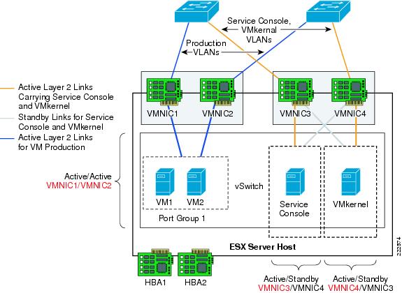
Access Layer Connectivity with Classic Access Layer Design
Both of the designs previously described (Figure 43 and Figure 44) can be attached to a Cisco LAN switching infrastructure in the possible design flavors depicted in Figure 39: the loop free U-shape design (which has no Spanning Tree blocking ports) and the V-shape design (which has one forwarding link per access switch, and the redundant link or links in blocking mode).
In order to further clarify the designs, consider Figure 45. In this diagram you can see how the U-shape access switches Catalyst1 and Catalyst2 connect to each other and to the aggregation layer. The direct link connecting the two access switches provides the Layer 2 adjacency required by the vmnics.
Rapid PVST+ provides fast Spanning Tree convergence, even if no port is in blocking state. The ESX hosts do not run Spanning Tree and connect in redundant fashion to both access switches. The access layer switches ports connecting to the ESX host for the VM production VLANs are trunks and are configured to carry the associated VLANs. The access layer switches ports connecting to the management ports are configured to trunk the Service Console VLAN and the VMkernel VLAN.
Figure 45 ESX Server with Cisco Switches U-shape Design
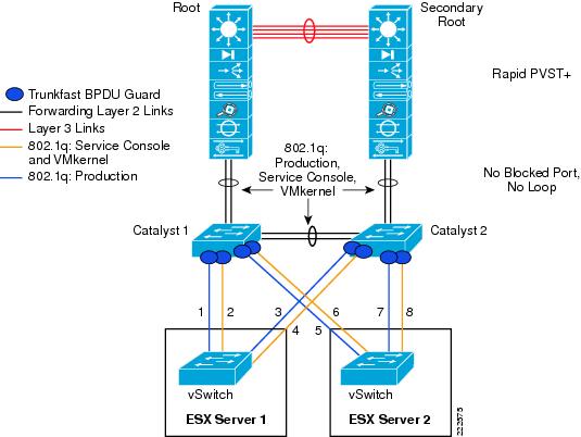
Figure 46 illustrates the design with the use of the Cisco V-shape LAN switching topology. The access switches Catalyst1 and Catalyst2 are dual-connected to the aggregation layer switches. The aggregation layer provides the root and secondary root function. Of the two set of links from the access layer, the one connecting to the secondary root is in Spanning-Tree blocking state.
As with the previous design, the access ports connecting to the ESX hosts are configured as 802.1q trunks carrying the Service Console VLAN and the VMkernel VLAN or the VM production VLANs.
Figure 46 ESX Server with Cisco Switches V-shape Design
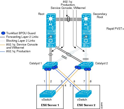
Access Layer Connectivity with EtherChannel
Given the availability of four NICs from an ESX host, it is possible to configure them as EtherChannels in many different ways, which also depends on the technology deployed at the Cisco access layer switch. Figure 47 shows an suboptimal topology where the two vmnics for production traffic are EtherChanneled to Catalyst1 and the two vmnics for Service Console and VMkernel traffic are EtherChanneled to Catalyst2. The main caveat of this topology is that if one Catalyst switch fails, it affects the operation of both ESX hosts. In this example, if the Catalyst 1 switch fails, ESX Server 1 cannot communicate on the production VLANs, thus isolating the VMs. At the same time, ESX2 loses the management connectivity which, if part of an VMware HA cluster may signifies that the VMs on ESX Server 2 may be powered off.
Figure 47 Suboptimal ESX EtherChannel Configuration
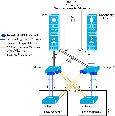
Figure 48 shows a better topology. In this topology each ESX host is connected to only one Catalyst switch (which may be operating with two supervisors in SSO mode). SSO provides Layer 2 high availability using redundant supervisors in an active/standby scenario, introducing approximately 0 to 3 seconds of packet loss when a supervisor switchover occurs. Attaching the ESX Server to a single access layer switch with supervisor redundancy may be an acceptable level of redundancy.
The EtherChannel from the ESX host to the Catalyst switch carries the VM production VLANs, Service Console, and VMkernel VLANs. Two configurations are possible where you could carry production and management traffic together on all links: 1, 2, 3, and 4; or you could create two separate EtherChannels, one for production with 1 and 2 bundled and one for management with 3 and 4 bundled.
In a VMware HA Cluster configuration between ESX Server1 and ESX Server2, the failure of Catalyst 1 or Catalyst 2 switch would sever the HA heartbeat connection between the two servers. This would cause ESX Server1 to bring down its virtual machines and ESX Server2 to power up its virtual machines.
Figure 48 ESX EtherChannel Configuration with Catalyst Switches
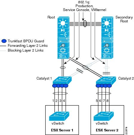
Finally, it is also possible to configure ESX Servers to run an EtherChannel across clustered Catalyst switches as depicted in Figure 49. In this diagram, you can see the access switch portion of the configuration where ESX Servers 1 and 2 are connected to both switches in the cluster.
Figure 49 ESX EtherChannel Configuration with Clustered Switches (like Cisco VSS or VBS Technology)
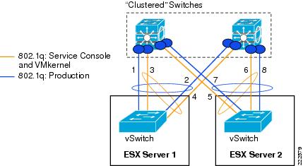
Two EtherChannel configurations are possible: one in which links 1, 2, 3, and 4 are bundled together can carry both production and management traffic, or (as shown in Figure 49) one in which one EtherChannel linking wires 1 and 2 carries the production traffic and one EtherChannel linking interfaces 3 and 4 carries the management traffic.
SAN Connectivity
Large scale VMware deployments use FibreChannel connectivity for the most part. ESX hosts in this case can boot off of the SAN, and Guest Operating systems access storage via the virtual SCSI controller. The packet flow looks as follows (see Figure 50):
•![]() The virtual machine issue a read/write command to the disk.
The virtual machine issue a read/write command to the disk.
•![]() The guest operating system driver sends the request to the virtual SCSI controller.
The guest operating system driver sends the request to the virtual SCSI controller.
•![]() The virtual SCSI controller sends the command to the VMkernel.
The virtual SCSI controller sends the command to the VMkernel.
•![]() VMkernel locates VM file on VMFS, maps virtual to physical blocks, sends request to physical HBA driver.
VMkernel locates VM file on VMFS, maps virtual to physical blocks, sends request to physical HBA driver.
•![]() HBA sends FCP operations out the wire.
HBA sends FCP operations out the wire.
Figure 50 ESX Host Storage Architecture
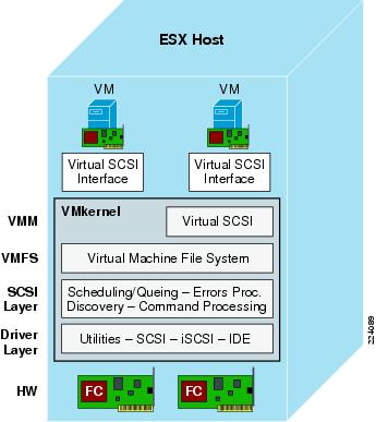
The VMFS layer makes the underlying FibreChannel and disk arrays appear as a homogeneous pool of storage space. VMFS provides many valuable services like ease of administration, LUN aggregation, and VM locking for clustering.
FibreChannel Implementation Considerations
There are two important design aspects in deploying VMware in a FibreChannel environment. One has to do with the zoning, and the second one has to do with multipathing. All VMs running on a single ESX Server access the storage via the same physical HBA; therefore, on the FibreChannel network there is a single login and zoning needs to consider only one port World Wide Name.
Zoning and LUN Masking
SAN best practices dictate the use of a common model to best manage, protect and secure data in a FibreChannel connected storage area network. Key practices include:
•![]() Logical Unit Number (LUN) masking is an authorization process that makes a logical unit number available to some hosts and unavailable to other hosts. LUN masking is usually used to protect data corruption caused by misbehaving servers.
Logical Unit Number (LUN) masking is an authorization process that makes a logical unit number available to some hosts and unavailable to other hosts. LUN masking is usually used to protect data corruption caused by misbehaving servers.
•![]() LUN mapping refers to the conversion between the physical SCSI device (storage) logical unit number and the logical unit number of the storage presented to operating environments.
LUN mapping refers to the conversion between the physical SCSI device (storage) logical unit number and the logical unit number of the storage presented to operating environments.
Implementation of these SAN best practices typically requires the use of an HBA Worldwide Port Name as a means of specifying the data path between the server and the storage LUN. As of this writing this data path is predicated on the physical WWPN of the HBA installed in the server: the physical HBA port World Wide Name is the same for all the virtual machines. This is depicted in Figure 51.
Figure 51 ESX FibreChannel Configuration
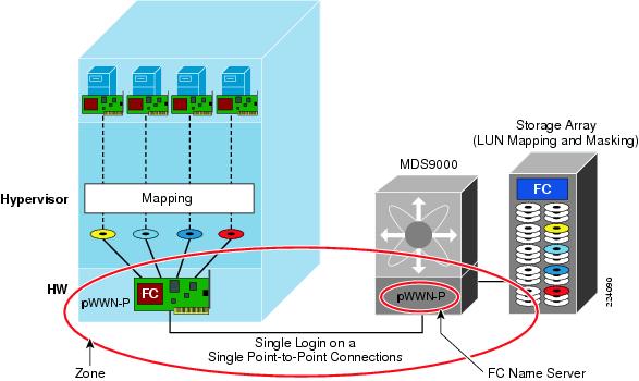
In addition to zoning an ESX Server to a disk array and properly configuring LUN masking, you need to consider which ESX hosts are part of the same cluster. VMotion migration can happen from one ESX host to a different ESX host in the same cluster. This requires that both hosts be zoned to see the same storage. From a FibreChannel perspective, this zoning configuration is open in that all ESX hosts in the same cluster can see all the LUNs and the VMFS provides on-disk distributed locking mechanism to prevent data corruption.
Note ![]() N-Port ID Virtualization provides more granular control on what a VM is allowed to see.
N-Port ID Virtualization provides more granular control on what a VM is allowed to see.
Multipathing
You cannot install products like EMC Powerpath or the likes on the VM because multipathing is performed at the SCSI mid-layer and not by the guest operating system. The ESX Server automatically identifies all available paths to a storage array and collapses it to one single active path (regardless of how many paths are available). As a result, the VMware ESX host provides only one active path and a failover mechanism should the primary path disappears.
N-Port ID Virtualization
One of the new technologies that is available as part of VMware ESX Server 3.5, is support for the N-Port ID Virtualization standard (NPIV). NPIV is a T11 ANSI standard which was developed by Emulex and IBM, to provide the capability for a fabric switch to register several WWPN on the same physical HBA port.
Support of NPIV enables each virtual machine (VM) on a VMware ESX Server to have a unique FibreChannel Worldwide Port Name (WWPN) providing an independent data path to the SAN through the Virtual HBA Port. By providing a unique virtual HBA port, storage administrators can implement SAN best practices such as LUN-masking and zoning for individual virtual machines.
How it Works
When a virtual machine has a WWN assigned to it, the virtual machine's configuration file (.vmx) is updated to include a WWN pair (consisting of a WWPN and a World Wide Node Name (WWNN)). As that virtual machine is powered on, the VMkernel instantiates a virtual port (VPORT) on the physical HBA that is used to access the LUN. The VPORT is a virtual HBA that appears to the FiberChannel fabric as a physical HBA; that is, it has its own unique identifier, the WWN pair, that was assigned to the virtual machine. Each VPORT is specific to the virtual machine, and the VPORT is destroyed on the host and it no longer appears to the FiberChannel fabric when the virtual machine is powered off.
Requirements
NPIV has the following requirements:
•![]() NPIV can only be used for virtual machines with RDM disks. Virtual machines with regular virtual disks use the WWNs of the host's physical HBAs. For more information on RDMs, see the ESX Server 3 Configuration Guide or ESX Server 3i Configuration Guide.
NPIV can only be used for virtual machines with RDM disks. Virtual machines with regular virtual disks use the WWNs of the host's physical HBAs. For more information on RDMs, see the ESX Server 3 Configuration Guide or ESX Server 3i Configuration Guide.
•![]() The physical HBAs on an ESX Server host must have access to all LUNs that are to be accessed by virtual machines running on that host.
The physical HBAs on an ESX Server host must have access to all LUNs that are to be accessed by virtual machines running on that host.
•![]() The ESX Server host's physical HBAs must support NPIV. Currently, the following vendors and types of HBA provide this support: QLogic—any 4GB HBA; Emulex—4GB HBAs that have NPIV compatible firmware.
The ESX Server host's physical HBAs must support NPIV. Currently, the following vendors and types of HBA provide this support: QLogic—any 4GB HBA; Emulex—4GB HBAs that have NPIV compatible firmware.
•![]() When a virtual machine or template with a WWN assigned to it is cloned, the clones do not retain the WWN.
When a virtual machine or template with a WWN assigned to it is cloned, the clones do not retain the WWN.
•![]() FibreChannel switches must be NPI-aware.
FibreChannel switches must be NPI-aware.
•![]() Always use the VI client to manipulate virtual machines with WWNs.
Always use the VI client to manipulate virtual machines with WWNs.
WWN Assignment
You can assign a WWN to a new virtual machine with an RDM disk when you create this virtual machine, or to an existing virtual machine you can temporarily power off.
To create a virtual machine with an RDM all you need to do is to go in the Virtual Machine configuration where you choose the type of SCSI adapter. There, you should select Raw Device Mapping. From a list of SAN disks or LUNs, you would select a raw LUN you want the virtual machine to access directly. You can then choose an existing datastore or specify a new one.
In the compatibility mode, menu you can select either physical or virtual:
•![]() Physical compatibility—Allows the guest operating system to access the hardware directly. Physical compatibility is useful if you are using SAN-aware applications in the virtual machine. However, a virtual machine with the physical compatibility RDM cannot be cloned, made into a template, or migrated if the migration involves copying the disk.
Physical compatibility—Allows the guest operating system to access the hardware directly. Physical compatibility is useful if you are using SAN-aware applications in the virtual machine. However, a virtual machine with the physical compatibility RDM cannot be cloned, made into a template, or migrated if the migration involves copying the disk.
•![]() Virtual compatibility—Allows the RDM to behave as if it were a virtual disk, so you can use such features as snapshotting, cloning, and so on. Depending on your choice, subsequent screens offer different options.
Virtual compatibility—Allows the RDM to behave as if it were a virtual disk, so you can use such features as snapshotting, cloning, and so on. Depending on your choice, subsequent screens offer different options.
The WWN can be assigned from the Specify Advanced Options page, where can change the virtual device node in the menu To assign or modify WWNs.
Zoning
As of the writing of this document, zoning requires use of the HBA Worldwide Port Name to identify the data path. In ESX 3.5, zoning can be used to isolate VMs running on the same ESX Server from one another. Since all physical HBAs and array controllers must be visible to VMkernel, an array port requires two zones:
•![]() A working zone, including the virtual port linked to a VM and the array port for the LUN used by the VM.
A working zone, including the virtual port linked to a VM and the array port for the LUN used by the VM.
•![]() A control zone, including all physical HBA ports on the ESX Server and all array ports attached to that ESX Server.
A control zone, including all physical HBA ports on the ESX Server and all array ports attached to that ESX Server.
Also note that with zoning and VMotion, the control zone must include all physical HBA ports of the ESX Server you might want to migrate to.
Figure 52 illustrates three VMs on two servers. Zoning is used to provide isolation for different users, applications, or departments. In this case, each individual disk is placed in an individual zone together with the related virtual initiator. The zone P includes physical devices, that are the physical HBAs (pWWN-P1, pWWN-P2) and the disks (pWWN-D1, pWWN-D2, pWWN-D3). Each zone Vx includes only the virtual HBA (pWWN-Vx) and the physical disk Dx (pWWN-Dx).
Figure 52 Virtual Machines using NPIV
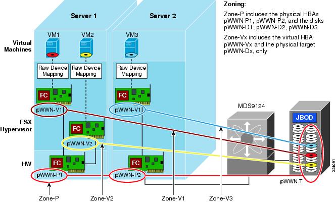
Note ![]() The VMkernel must have visibility to all the LUNs used by all the virtual machines on the system. For practical purposes, it is recommended to set up and mask each LUN to make them visible to the physical HBA WWPN (and thereby to VMkernel) and the virtual WWPN associated with the VM that will use it, blocking out all other virtual WWPNs and VMs.
The VMkernel must have visibility to all the LUNs used by all the virtual machines on the system. For practical purposes, it is recommended to set up and mask each LUN to make them visible to the physical HBA WWPN (and thereby to VMkernel) and the virtual WWPN associated with the VM that will use it, blocking out all other virtual WWPNs and VMs.
VMotion in an NPIV Environment
With ESX Server leveraging NPIV, a virtual HBA or VPORT can be created for each VM. Figure 53 and Figure 54 illustrate how LUN mapping works in a future ESX Server environment with NPIV-aware VMotion- enabled. Note that the requirements and behaviors for LUN masking will vary by array.
In Figure 53, each LUN x is exposed only to the physical initiators (pWWN-P1, pWWN-P2) and to virtual machine VMx (pWWN-Vx). The zone P includes the physical devices, that are the physical HBAs (pWWN-P1, pWWN-P2) and the storage array port (pWWN-T). Each zone Vx includes only the VMx virtual HBA (pWWN-Vx) and the storage array port (pWWN-T).
Figure 54 depicts a VMotion migration of VM-2 from SRV-1 to SRV-2. The SAN configuration is unchanged. Zone V2 is unchanged, but now VM2 is located in SRV-2. LUN mapping and masking is unchanged.
Using NPIV a virtual machine can be relocated from one physical ESX Server to another, without the storage and fabric administrator being requested to change any zoning or LUN mapping and masking settings. At the same time the storage access is protected from any other virtual server by both zoning and LUN masking and mapping, as it is common practice for any physical server.
Figure 53 Virtual Machines Using NPIV: Zoning, LUN Masking
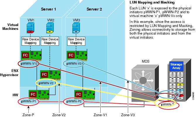
Figure 54 Virtual Machines Using NPIV: Zoning, LUN Masking and Mapping after VM2 VMotion from Server 1 to Server 2

Multipathing
If NPIV is enabled, four WWN pairs (WWPN and WWNN) are specified for each virtual machine at creation time. When a virtual machine using NPIV is powered on, it uses each of these WWN pairs in sequence to try to discover an access path to the storage. The number of VPORTs that are instantiated equals the number of physical HBAs present on the host up to the maximum of four. A VPORT is created on each physical HBA that a physical path is found on. Each physical path is used to determine the virtual path that will be used to access the LUN. As is the case without NPIV, all FibreChannel multipathing is active/passive.
Note ![]() The HBAs that are not NPIV-aware are skipped in this discovery process because VPORTs cannot be instantiated on them.
The HBAs that are not NPIV-aware are skipped in this discovery process because VPORTs cannot be instantiated on them.
Troubleshooting
Fcping is used to determine the basic connectivity between two FibreChannel network points, as well as monitor and measure network latency. Traceroute reports on a SAN path, including node hops and latency data. Both fcping and fctraceroute can be used for connectivity from either the physical, or with NPIV, a virtual HBA associated with a VM.
Benefits
The following is a list of advantages when using NPIV within the VMware ESX Server. These benefits are listed in order of the relative benefit to the IT community.
•![]() As each NPIV entity is seen uniquely on the SAN, it is possible to track the individual SAN usage of a virtual server. Prior to NPIV, the SAN and ESX Server could only see the aggregate usage of the physical FC port by all of the virtual machines running on that system.
As each NPIV entity is seen uniquely on the SAN, it is possible to track the individual SAN usage of a virtual server. Prior to NPIV, the SAN and ESX Server could only see the aggregate usage of the physical FC port by all of the virtual machines running on that system.
•![]() Virtual machines can be associated to devices mapped under RDM to allow for LUN tracking and customization to the application needs. SAN tools tracking individual FCID and WWPN can report virtual machine specific performance or diagnostic data. As each NPIV entity is seen uniquely on the SAN, switch-side reporting tools and array-side tools can report diagnostic and performance-related data on a virtual machine basis.
Virtual machines can be associated to devices mapped under RDM to allow for LUN tracking and customization to the application needs. SAN tools tracking individual FCID and WWPN can report virtual machine specific performance or diagnostic data. As each NPIV entity is seen uniquely on the SAN, switch-side reporting tools and array-side tools can report diagnostic and performance-related data on a virtual machine basis.
•![]() Bi-Directional Association of Storage with virtual machines gives administrations the ability to both trace from a virtual machine to a LUN provisioned on the SAN, but also be able to trace back from a LUN provisioned on the SAN to a VM (significantly enhanced with NPIV support).
Bi-Directional Association of Storage with virtual machines gives administrations the ability to both trace from a virtual machine to a LUN provisioned on the SAN, but also be able to trace back from a LUN provisioned on the SAN to a VM (significantly enhanced with NPIV support).
•![]() Storage provisioning for ESX Server-hosted virtual machines can use the same methods, tools, and expertise in place for physical servers. As the virtual machine is once again uniquely related to a WWPN, traditional methods of zoning and LUN masking can continue to be used.
Storage provisioning for ESX Server-hosted virtual machines can use the same methods, tools, and expertise in place for physical servers. As the virtual machine is once again uniquely related to a WWPN, traditional methods of zoning and LUN masking can continue to be used.
•![]() Fabric zones can restrict target visibility to selected applications. Configurations that required unique physical adapters based on an application can now be remapped on to unique NPIV instances on the ESX Server.
Fabric zones can restrict target visibility to selected applications. Configurations that required unique physical adapters based on an application can now be remapped on to unique NPIV instances on the ESX Server.
•![]() Virtual machine migration supports the migration of storage visibility. Access to storage can be limited to the ESX Server actively running the virtual machine. If the virtual machine is migrated to a new ESX Server, no changes in SAN configuration would be required to adjust for the use of different physical Fibre Channel ports as the virtual machine's assigned WWN is maintained.
Virtual machine migration supports the migration of storage visibility. Access to storage can be limited to the ESX Server actively running the virtual machine. If the virtual machine is migrated to a new ESX Server, no changes in SAN configuration would be required to adjust for the use of different physical Fibre Channel ports as the virtual machine's assigned WWN is maintained.
•![]() HBA upgrades, expansion, and replacement is now seamless. As the physical HBA WWPNs are no longer the entities upon which the SAN zoning and LUN-masking is based, the physical adapters can be replaced or upgraded without any change to SAN configuration.
HBA upgrades, expansion, and replacement is now seamless. As the physical HBA WWPNs are no longer the entities upon which the SAN zoning and LUN-masking is based, the physical adapters can be replaced or upgraded without any change to SAN configuration.
Performance Considerations
VMware deployments are often associated with consolidation projects whose goal is to aggregate applications with lower I/O onto the same physical machine. This results in fewer FibreChannel ports being used, but higher bandwidth utilization on the remaining ports. The Cisco MDS9000 offers several tools to optimize bandwidth utilization of ESX Servers.
MDS Port Group Selection
The Cisco MDS linecards with flexible bandwidth allocation can be reconfigured to address the requirement for higher bandwidth. Take for example the 24 ports module. This linecards provides four Cisco MDS Port Groups (see note below for explanations on what a Port Group is). You could allocate up to 4Gbps bandwidth to the ESX host HBAs, depending on the needs, up to 3 per Port Group and shut down the remaining ports, or use the remaining ports in shared mode for non-ESX Servers. When a Port Group is fully utilized (e.g., 3 x 4Gbps dedicated ports) , you should start using the ports from a different Port Group.
Note ![]() Port Group in Cisco terminology referring to a grouping of ports sharing a certain level of bandwidth. Depending on the bandwidth allocation, you could have dedicated 4Gbps or 2Gbps bandwidth to a set of ports and a 4Gbps or 2Gbps shared bandwidth allocated to the remaining ports, with a total available bandwidth that cannot exceed 12Gbps.
Port Group in Cisco terminology referring to a grouping of ports sharing a certain level of bandwidth. Depending on the bandwidth allocation, you could have dedicated 4Gbps or 2Gbps bandwidth to a set of ports and a 4Gbps or 2Gbps shared bandwidth allocated to the remaining ports, with a total available bandwidth that cannot exceed 12Gbps.
FibreChannel Congestion Control
FibreChannel Congestion Control (FCC) is a Cisco proprietary flow control mechanism that alleviates congestion on FibreChannel networks. For more information, refer to the following URL: http://www.cisco.com/en/US/products/ps5989/products_configuration_guide_chapter09186a0080663141.html
FCC slows down the source by pacing the generation of Receiver Ready frames on the F-port connecting to the source. In the case of VMware deployments, this feature should be used with caution because several VMs are situated behind a single HB; so if one VM is causing congestion, all the VMs on the same machine would be slowed down.
Quality of Service (with NPIV)
Using the Cisco MDS Fabric Manager console, the administrator can assign a traffic priority level of high, medium, or low to any initiator WWPN (physical or virtual). In a local SAN where congestion issues are generally minimal, setting different priority levels to different ports will not bring any visible results. QoS without NPIV is not very useful in VMware environment because all VMs would end up in the same priority.
With NPIV, the administrator can assign each VM individually to a different QoS priority. For example, the same server may use remote mirroring for one VM, requiring very short response times, while another VM will be set up to send backup files to a remote backup server or virtual tape appliance. In this case, the user will want to assign a high priority to the virtual WWPN engaged in remote mirroring, and a low priority to the WWPN for backup.
Figure 55 shows a configuration where QoS is used to prioritize bandwidth allocation in cases where this bandwidth may be restricted, such as remote SAN access by IP or DWDM gateways. In this case, the traffic generated by VM1 has higher priority with respect to the traffic generated by VM2, or by other devices sharing the common infrastructure. A SCSI traffic generator like IOmeter can be used to evaluate whether the performance requirements are met for a given configuration and set up the appropriate QoS level for a given VM.
Figure 55 QoS for VMs Using NPIV
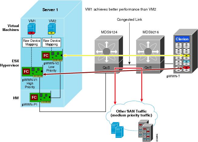
iSCSI Implementation Considerations
The iSCSI can be used to access storage from the ESX hosts. For iSCSI to work, both a VMkernel interface and a Service Console interface need to have access to the iSCSI target and be configured on the same vSwitch. The VMkernel handles iSCSI traffic as previously indicated.
A possible configuration is shown in Figure 17. Service Console 2, with the IP address 10.0.2.171 on VLAN 511 is used for management access to the ESX host; another Service Console instance, with IP address 10.0.200.173 on VLAN 200; a VMkernel instance on VLAN 200 with IP address 10.0.200.171 is used for iSCSI software initiator; a VMkernel instance on VLAN100 with IP address 10.0.55.171 is used for VMotion.
To complete the configuration you need to go to the Firewall Properties configuration (select the ESX Host, Configuration tab, look at the Software box, Security Profile, Properties) to allow the iSCSI software initiator traffic.
The iSCSI initiator configuration is shown in Figure 56. Once you have selected an ESX host in the Configuration tab, you select Storage Adapters. Here, you can find iSCSI Software Adapter, which allows you to enable the initiator (see Figure 56).
Figure 56 Enabling the iSCSI Initiator
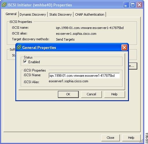
From the Dynamic Discovery tab, you can then Add Send Targets Server, where you provide the iSCSI target IP address. See Figure 57.
Note ![]() In case the iSCSI target is provided by a Cisco MDS9000 family FibreChannel switch or director equipped with an IPS (IP service Module) blade, the iSCSI Server address can be made highly available by using a VRRP (virtual router) address. The virtual router address is mapped to a physical MDS9000 gigabit Ethernet interface in an active-passive fashion (pure VRRP group) or using iSLB (iSCSI Server Load Balancing - active VRRP group).
In case the iSCSI target is provided by a Cisco MDS9000 family FibreChannel switch or director equipped with an IPS (IP service Module) blade, the iSCSI Server address can be made highly available by using a VRRP (virtual router) address. The virtual router address is mapped to a physical MDS9000 gigabit Ethernet interface in an active-passive fashion (pure VRRP group) or using iSLB (iSCSI Server Load Balancing - active VRRP group).
Figure 57 Discovering iSCSI Targets
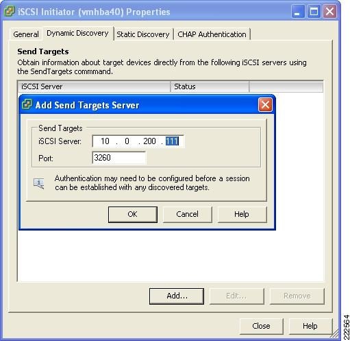
VMotion Networking
VMotion is the method used by ESX Server to migrate powered-on VMs within an ESX farm/datacenter (in VMware VirtualCenter terminology) from one physical ESX host to another. VMotion is perhaps the most powerful feature of an ESX virtual environment, allowing the movement of active VMs with minimal downtime. Server administrators may schedule or initiate the VMotion process manually through the VMware VirtualCenter management tool.
The VMotion process occurs in the following steps:
Step 1 ![]() VirtualCenter verifies the state of the VM and target ESX host. VirtualCenter determines the availability of resources necessary to support the VM on the target host.
VirtualCenter verifies the state of the VM and target ESX host. VirtualCenter determines the availability of resources necessary to support the VM on the target host.
Step 2 ![]() If the target host is compatible (e.g., CPU of same vendor and family), a copy of the active VMs state is sent from the source ESX host to the target ESX host. The state information includes memory, registers, network connections, and configuration information. Note that the memory state is copied during the pre-copy state and the all device state is moved only after the VM is stunned.
If the target host is compatible (e.g., CPU of same vendor and family), a copy of the active VMs state is sent from the source ESX host to the target ESX host. The state information includes memory, registers, network connections, and configuration information. Note that the memory state is copied during the pre-copy state and the all device state is moved only after the VM is stunned.
Step 3 ![]() The source ESX Server VM is suspended.
The source ESX Server VM is suspended.
Step 4 ![]() The .vmdk file (virtual disk) lock is released by the source ESX host.
The .vmdk file (virtual disk) lock is released by the source ESX host.
Step 5 ![]() The remaining copy of state information is sent to the target ESX host.
The remaining copy of state information is sent to the target ESX host.
Step 6 ![]() The target ESX host activates the new resident VM and simultaneously locks its associated .vmdk file.
The target ESX host activates the new resident VM and simultaneously locks its associated .vmdk file.
Step 7 ![]() The vSwitch on the target ESX host is notified, vSwitch generates a RARP for the MAC address of the the VM. This updates the Layer 2 forwarding tables on the Cisco Catalyst switches. No Gratuitous ARP is needed as the MAC address of the VM does not change during the VMotion process.
The vSwitch on the target ESX host is notified, vSwitch generates a RARP for the MAC address of the the VM. This updates the Layer 2 forwarding tables on the Cisco Catalyst switches. No Gratuitous ARP is needed as the MAC address of the VM does not change during the VMotion process.
Figure 58 shows the VMotion process and the key components in the system: the SAN-based VMFS volume accessible by both ESX hosts and the VLAN segments, the one used to synchronize memory information (VMotion network, which is the network connecting the VMkernels), and the production network which is the network used for the client-access to the application running on the VMs.
Figure 58 VMotion Process
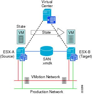
VMotion is not a full copy of a virtual disk from one ESX host to another but rather a copy of "state". The .vmdk file resides in the SAN on a VMFS partition and is stationary; the ESX source and target servers simply swap control of the file lock after the VM state information synchronizes.
Deploying a VMotion-enabled ESX Server farm requires the following:
•![]() VirtualCenter management software with the VMotion module.
VirtualCenter management software with the VMotion module.
•![]() ESX farm/datacenter (VMotion only works with ESX hosts that are part of the same data center in the VirtualCenter configuration). Each host in the farm should have almost-identical hardware processors to avoid errors after migration (check the compatibility information from VMware)
ESX farm/datacenter (VMotion only works with ESX hosts that are part of the same data center in the VirtualCenter configuration). Each host in the farm should have almost-identical hardware processors to avoid errors after migration (check the compatibility information from VMware)
•![]() Shared SAN, granting access to the same VMFS volumes (.vmdk file) for source and target ESX hosts.
Shared SAN, granting access to the same VMFS volumes (.vmdk file) for source and target ESX hosts.
•![]() Volume names used when referencing VMFS volumes to avoid WWN issues between ESX hosts.
Volume names used when referencing VMFS volumes to avoid WWN issues between ESX hosts.
•![]() VMotion "connectivity" (i.e., reachability of VMkernels from originating to target ESX host and vice versa). It may be desirable to have Gigabit Ethernet network for state information exchange, although VMotion will work just fine on a VLAN.
VMotion "connectivity" (i.e., reachability of VMkernels from originating to target ESX host and vice versa). It may be desirable to have Gigabit Ethernet network for state information exchange, although VMotion will work just fine on a VLAN.
•![]() The ESX originating host and the ESX target host need to have the same Network Label configured with the same Security Policy configuration.
The ESX originating host and the ESX target host need to have the same Network Label configured with the same Security Policy configuration.
Note ![]() Regular migration (i.e., non-VMotion migration) is the migration of a powered off VMs. This type of migration does not present any special challenge in that there is no memory replication, and if a SAN is present the VMFS volumes are already visible by the ESX hosts in the same data center. In case a relocation is involved (i.e., in the case where the .vmdk disk file needs to be moved to a different datastore) the MAC address of the powered-on VM may change.
Regular migration (i.e., non-VMotion migration) is the migration of a powered off VMs. This type of migration does not present any special challenge in that there is no memory replication, and if a SAN is present the VMFS volumes are already visible by the ESX hosts in the same data center. In case a relocation is involved (i.e., in the case where the .vmdk disk file needs to be moved to a different datastore) the MAC address of the powered-on VM may change.
VMotion Migration on the same Subnet (Flat Networks)
The most common deployment of VM migration requires Layer 2 adjacency between the machines involved (see Figure 59). The scope of the Layer 2 domain is for the most part limited to the access layer hanging off of the same pair of aggregation switches, or in other words typically either within the same facility (building) or at a maximum across buildings in a campus, and typically involves 10 to 20 ESX hosts at a maximum due to the requirements of the host to be part of the same data center for migration purposes and of the same cluster for DRS purposes.
A Layer 2 solution for a VMware cluster satisfies the requirements of being able to turn on a machine anywhere within the cluster as well as migrating an active machine from an ESX Server to a different one without noticeable disruption from the user (VMotion).
Figure 59 VMware Layer 2 Domain Requirements
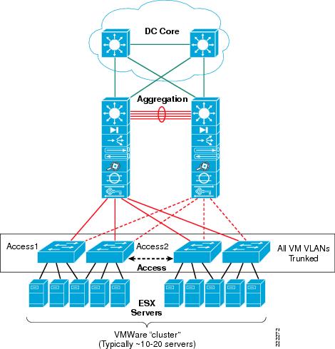
VMotion is better explained starting from a real example. Imagine a server farm deployment such as the one shown in Figure 60. ESX Server Host 1 is in Rack 1 in the data center. ESX Server Host 2 is in Rack 10 in the same data center. Each rack provides Layer 2 connectivity to the servers (design approach referred to as top of the rack design). A pair of Layer 3 switches interconnects the racks which may very well be several rows away from each other. The goal of the implementation is to be able to move VM4 from ESX Server Host 2 in Rack 10 to ESX Server Host 1 in Rack 1.
Figure 60 VMotion Migration on a Layer 2 Network
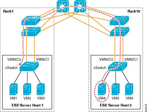
For this to happen, you need to provision the network to carry VMkernel traffic from ESX Server Host 2 to ESX Server Host 1 and you need to make sure that VM4 can be reached by clients when running in ESX Server Host 1.
A solution that meets these requirements is the following:
•![]() Provisioning a VLAN for the VMkernel
Provisioning a VLAN for the VMkernel
•![]() Trunking this VLAN from ESX Server Host 2 all across the LAN network to ESX Server Host 1
Trunking this VLAN from ESX Server Host 2 all across the LAN network to ESX Server Host 1
•![]() Provisioning a VLAN for VM public access
Provisioning a VLAN for VM public access
•![]() Trunking this VLAN from ESX Server Host 2 all across the LAN network to ESX Server Host 1
Trunking this VLAN from ESX Server Host 2 all across the LAN network to ESX Server Host 1
•![]() Making sure that the VMkernel VLAN and the VM VLANs are separate (although they may share the same physical links)
Making sure that the VMkernel VLAN and the VM VLANs are separate (although they may share the same physical links)
The ESX host configuration would look like Figure 61. The ESX host would have a vSwitch with its own dedicated NIC for the VMkernel. The VMkernel VLAN would be trunked from the aggregation switch to the access switches in Rack 1 all the way to the vSwitch in ESX Server Host 2.
Similarly, the VM4 VLAN and the Network Label would be identical on vSwitch2/ESX Server Host 2 as in vSwitch2/ESX Server Host1.
Figure 61 VM Mobility and VLAN Assignment
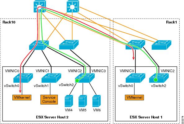
ESX HA Cluster
As previously explained, a VMware ESX HA cluster differs from regular HA clusters—it does not provide application availability, but the capability to restart VMs that were previously running on a failed ESX host onto a different ESX host.
An HA agent runs in each ESX host and is used to monitor the availability of the other ESX hosts that are part of the same VMware HA cluster. ESX hosts network monitoring is achieved with unicast UDP frames that are exchanged on the Service Console VLAN, or VLANs if multiple Service Consoles are configured. The agents use four different UDP ports such as ~8042. UDP heartbeats are sent every second. No heartbeats are exchanged on the production VLANs. Note that ESX HA requires the Domain Name Service (DNS) for initial configuration.
When an ESX host loses connectivity via the heartbeats to other ESX hosts, it starts pinging the gateway to verify if it still has access to the network or whether it has become isolated. In principle, if an ESX host finds out that it is isolated, it will power down the VMs so that the lock on the .vmdks file is released and the VMs can be restarted on other ESX hosts.
Note that the default settings will shutdown VMs to avoid split-brain scenarios. ESX assumes a highly available and redundant network that makes network isolations highly rare. HA recommendations are as follows:
Step 1 ![]() Configure two Service consoles on different networks.
Configure two Service consoles on different networks.
Step 2 ![]() Configure each Service Console with two teamed vmnics with Rolling Failover = Yes (ESX 3.0.x) or Failback = No (ESX 3.5).
Configure each Service Console with two teamed vmnics with Rolling Failover = Yes (ESX 3.0.x) or Failback = No (ESX 3.5).
Step 3 ![]() Ensure the teamed vmnics are attached to different physical switches.
Ensure the teamed vmnics are attached to different physical switches.
Step 4 ![]() Ensure there is a completely redundant physical path between the ESX hosts with no single points of failure that could cause a split-brain scenario.
Ensure there is a completely redundant physical path between the ESX hosts with no single points of failure that could cause a split-brain scenario.
Just like with VMware for a VM to restart on a different ESX host, there needs to be a Network Label where the VM connects to when powered-on. The following failure scenarios help explaining the behavior of the VMware HA cluster.
For more information on VMware ESX HA, refer to the VMware HA: Concepts and Best Practices technical paper at:
http://www.vmware.com/resources/techresources/402
Maintenance Mode
In this first example, esxserver1 is put into Maintenance Mode. The VM is VMotion migrated to esxserver2 as it is shown in Figure 62. Note that from a network's perspective, the only requirement for a VM to move to esxserver2 is that the same Network Label exists. For the clients to keep working on the migrating VM, this Network Label must be the same VLAN as esxserver1 and there must be vmnics trunking this VLAN to the Cisco Catalyst switches.
Note ![]() Apart from the naming of the Network Label , VirtualCenter and the HA cluster software do not verify either the VLAN number or the presence of vmnics on the vSwitch. It is up to the administrator to ensure that VLAN configurations and vmnics are correctly configured before hand.
Apart from the naming of the Network Label , VirtualCenter and the HA cluster software do not verify either the VLAN number or the presence of vmnics on the vSwitch. It is up to the administrator to ensure that VLAN configurations and vmnics are correctly configured before hand.
Figure 62 HA Cluster and ESX Host Maintenance Mode
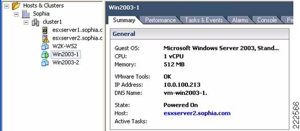
ESX Host Disconnected from Production, Management and Storage
In this example, the ESX Server Host 1 is connected via a single vmnic to the LAN switching network (see Figure 63). One VLAN provides network management access (10.0.2.0), one VLAN provides access to the production network (10.0.100.0), and one VLAN provides access to the SAN via iSCSI (10.0.200.0).
Figure 63 HA Cluster and NIC Failure

When the NIC vmnic0 gets disconnected, ESX1 connectivity is lost on all VLANs. The HA agent on ESX2 determines that ESX1is not reachable via the Service Console network, and it tries to reserve the VMFS volumes to be able to start VM1 and VM2. Because ESX1 is not only isolated but also lost control for the iSCSI disks, the lock eventually times out and ESX2 can reserve the disks and restart VM1 and VM2. The total time for the VMs to be restarted is approximately 18 to 20 seconds.
Note ![]() During this process, ESX2 tries to reach ESX1 several times before declaring it failed and it also verifies that it can reach the gateway.
During this process, ESX2 tries to reach ESX1 several times before declaring it failed and it also verifies that it can reach the gateway.
Note ![]() If you happen to watch the failure of ESX1 from the VirtualCenter, do not expect to see that vmnic0 is marked as failed. Losing vmnic0 means that you also lost network management connectivity, so VirtualCenter cannot collect status information from ESX1 any longer.
If you happen to watch the failure of ESX1 from the VirtualCenter, do not expect to see that vmnic0 is marked as failed. Losing vmnic0 means that you also lost network management connectivity, so VirtualCenter cannot collect status information from ESX1 any longer.
Overall, having two vmnics configured for NIC teaming provides a faster convergence time than having to restart VMs in a different ESX host.
Lost Connectivity on Service Console Only
Imagine now a network similar to Figure 63 modified in a way that the vmnic for the Service Console is separate from the other vmnics used for production, VMkernel, and iSCSI traffic. If the Service Console vmnic fails on ESX Host 1, the ESX Host 1 appears as disconnected from the VirtualCenter, due to the lack of management communication, but the ESX Host 1 is still up and running and the VMs are powered-on. If ESX Host 2 can still communicate with ESX Host1 over a redundant Service Console (which may be not routed), the VMs do not need to be powered off and restarted on ESX Host 2.
A redundant Service Console is recommended. The software iSCSI initiator is implemented using the VMkernel address. The iSCSI uses the Service Console for authentication; therefore, it must have Layer 3 or Layer 2 connectivity to the iSCSI VLAN or network.
Lost Connectivity on Production Only
Consider Figure 63 and imagine that the NIC on ESX1 is not disconnected, but that for some reason the path on the production network is not available (most likely due to a misconfiguration). The HA cluster is not going to shutdown the VM on ESX1 and restart it on ESX2, because ESX1 and ESX2 can still communicate on the Service Console network. The result is that VMs on ESX1 are isolated.
Similarly, assume that ESX1 has two vmnics, one used for the production network and one used for the Service Console, VMkernel and iSCSI. If the first vmnic fails, this is not going to cause VMs to be restarted on ESX2. The result is that VMs on ESX1 are isolated.
In order to avoid this scenario, the best solution is to not dedicate a single vmnic to production traffic alone, but to use vmnics configured for NIC teaming.
Additional Resources
For more information on ESX Server releases, visit the VMware technology network site at the following URLs:
http://www.vmware.com/support/pubs/vi_pubs.html
http://www.vmware.com/products/vc/
http://www.vmware.com/pdf/vi3_301_201_admin_guide.pdf
Cisco Catalyst 6500:
http://www.cisco.com/en/US/products/hw/switches/ps708/
Cisco Blade Switches:
http://www.cisco.com/en/US/products/ps6748/index.html
http://www.cisco.com/en/US/products/ps6294/index.html
http://www.cisco.com/en/US/products/ps6982/index.html
http://www.vmware.com/resources/techresources/
http://pubs.vmware.com/vi35/wwhelp/wwhimpl/js/html/wwhelp.htm
 Feedback