-
Cisco NAC Appliance - Clean Access Manager Configuration Guide, Release 4.9(2)
-
About This Guide
-
Introduction
-
Device Management: Adding Clean Access Servers, Adding Filters
-
Switch Management: Configuring Out-of-Band Deployment
-
Wireless LAN Controller Management: Configuring Wireless Out-of-Band Deployment
-
Configuring User Login Page and Guest Access
-
User Management: Configuring User Roles and Local Users
-
User Management: Configuring Authentication Servers
-
User Management: Traffic Control, Bandwidth, Schedule
-
Configuring Cisco NAC Appliance for Agent Login and Client Posture Assessment
-
Cisco NAC Appliance Agents
-
Monitoring and Troubleshooting Agent Sessions
-
Configuring Network Scanning
-
Monitoring Event Logs
-
Administering the CAM
-
Error and Event Log Messages
-
API Support
-
MIB Support
-
Open Source License Acknowledgements
-
 Feedback
Table Of Contents
Wireless LAN Controller Management: Configuring Wireless Out-of-Band Deployment
Wireless In-Band Versus Out-of-Band
Wireless Out-of-Band Requirements
Summary Steps to Configure Wireless Out-of-Band
Wireless Out-of-Band Virtual Gateway Deployment
Login and Authentication Flow in Wireless OOB Virtual Gateway Mode
Configure Your Network for Wireless Out-of-Band
Configure Your Wireless LAN Controllers
Wireless LAN Controllers Configuration Notes
Example Wireless LAN Controller Configuration Steps
Create the Dynamic Interface on the Wireless LAN Controller
Create the WLAN on the Wireless LAN Controller and Enable Cisco NAC Appliance Integration
Configure SNMP on the Wireless LAN Controller
Specify the CAM as the SNMP Trap Receiver
Wireless OOB Network Setup/Configuration Worksheet
Configure Wireless LAN Controller Connection on the CAM
Add a Wireless Out-of-Band Clean Access Server and Configure Environment
Configure Wireless LAN Controller Profiles
Add Wireless LAN Controller Profile
Add and Manage Wireless LAN Controllers
Add New Wireless LAN Controller
Search New Wireless LAN Controllers
View Wireless Out-of-Band Online Users
Wireless and Wired OOB User List Summary
Wireless LAN Controller Management: Configuring Wireless Out-of-Band Deployment
This chapter describes how to configure Cisco NAC Appliance for Wireless Out-of-Band (Wireless OOB) deployment. Topics include:
•
Wireless Out-of-Band Virtual Gateway Deployment
•
•
•
See Cisco NAC Appliance - Clean Access Server Configuration Guide, Release 4.9(2) for additional information on OOB deployments.
Overview
In a traditional In-Band Cisco NAC Appliance wireless deployment, all network traffic to or from wireless client machines passes through the Clean Access Server (CAS). For high throughput or highly routed environments, a Cisco NAC Appliance Wireless Out-of-Band (Wireless OOB) deployment allows client traffic to pass through the network only in order to be authenticated and certified before being connected directly to the access network.
Wireless Out-of-Band can be configured in the following deployments:
•
•
•
Note
Starting from NAC Appliance Release 4.9, the wireless OOB is supported for roaming as well. When the client machine roams, the connectivity is not lost.
Wireless Out-of-Band is supported in the following scenarios of roaming:
•
•
•
This section discusses the following topics:
•
•
•
Wireless In-Band Versus Out-of-Band
Table 4-1 summarizes different characteristics of each type of deployment.
Wireless Out-of-Band Requirements
Wireless Out-of-band implementation of Cisco NAC Appliance requires the following to be in place:
•
•
•
•
Note
The update WLC OID feature only applies to existing models. If a new WLC series is introduced, administrators will still need to upgrade to ensure Wireless OOB support for the new WLCs. See Configure and Download Updates.
Note
Local Switching is not supported with Cisco NAC Wireless OOB.
Note
DHCP Bridging Mode
To enable the DHCP bridging functionality on the controller, you must disable the DHCP proxy feature on the controller. By default, DHCP proxy is enabled.
In the 4.2.x.x codes this can be done using the CLI using the following commands:
(Cisco Controller) > config dhcp proxy disable(Cisco Controller) > show dhcp proxyDHCP Proxy Behavior: disabledThe DHCP bridging feature is a global setting, so it affects all DHCP transactions within the controller. You need to add ip helper statements in the wired infrastructure for all necessary VLANs on the controller.
You can disable the DHCP proxy through the User Interface as well. In the WLC graphical user interface, click Controller > Advanced > DHCP and uncheck the Enable DHCP Proxy check box as shown in Figure 4-1.
Figure 4-1
Disable DHCP Proxy
Note
SNMP Control
In a Wireless OOB deployment, you can add WLCs to the Clean Access Manager's domain and communicate with the WLC using the Simple Network Management Protocol (SNMP). SNMP is an application layer protocol used by network management tools to exchange management information between network devices. Cisco NAC Appliance and Cisco WLCs support the following SNMP versions in a Wireless OOB environment:
•
•
•
•
•
•
•
You first need to configure the WLC to send and receive SNMP traffic to/from the Clean Access Manager, then configure matching settings on the Clean Access Manager to send and receive traffic to/from the WLC. This will enable the Clean Access Manager to get VLAN information from the WLC and coordinate with the WLC when wireless users log out (or are "kicked out") of the network and removed from the Online Users list.
Summary Steps to Configure Wireless Out-of-Band
To enable Wireless OOB in you access network, you need to perform the following tasks:
1.
a.
b.
c.
2.
3.
Note
4.
5.
–
–
–
Wireless Out-of-Band Virtual Gateway Deployment
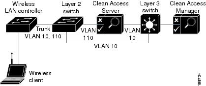
Figure 4-2 illustrates a typical Wireless OOB Virtual Gateway deployment. The WLC assigns two VLANs, AUthentication (Quarantine) VLAN 110 and Access VLAN 10, to one or more SSIDs/dynamic interfaces to support wireless client access. The WLC and the Layer 2 access switch have a VLAN trunk assignment for both VLANs so that client traffic automatically reaches the Layer 2 switch regardless of whether the wireless client machine has authenticated with Cisco NAC Appliance or not. The Layer 2 switch ensures that all unauthenticated traffic gets directed to the Clean Access Server via VLAN 110 and that authenticated clients remain Out-of-Band, thus bypasses the CAS and proceeding directly to the internal network via Access VLAN 10.
Figure 4-2 Wireless Out-of-Band Layer 2 VGW Mode
Login and Authentication Flow in Wireless OOB Virtual Gateway Mode
1.
2.
Note
If the device cannot run Java applet or ActiveX, then the MAC address is not detected and this leads to error.3.
4.
Note
Cisco WLCs do not support IPSec communication with the Cisco NAC Appliance network, so you cannot provide RADIUS SSO capability to users in your FIPS 140-2 compliant environment.5.
6.
When the user logs out of the wireless OOB network, the WLC sends another SNMP update to the CAM to ensure the CAM removes the user profile from the wireless Online Users list. Likewise, if the Cisco NAC Appliance administrator is forced to "kick" a user out of the network, the CAM sends an SNMP trap to the WLC and the WLC, in return, automatically moves the user back to the Authentication (Quarantine) VLAN, thus directing the now unauthenticated client traffic to the CAS.
Configure Your Network for Wireless Out-of-Band
The CAM communicates with associated WLCs using SNMP and manages Wireless OOB CASs through the admin network. The trusted interface of the CAS connects to the admin/management network, and the untrusted interface of the CAS connects to the managed client network.
When a wireless client connects to a WLC, the WLC automatically assigns the client to an Authentication (Quarantine) VLAN and the traffic to/from the client goes through the CAS. After the client is authenticated and certified through the Clean Access Server, the WLC receives an SNMP message from the CAM allowing the client access to the network via the Access VLAN. Once on the access VLAN, traffic to and from certified clients moves Out-of-Band, bypassing the Clean Access Server.
The next sections describe the configuration steps needed to set up your Wireless OOB deployment:
•
•
Configure Your Wireless LAN Controllers
This section describes the steps needed to set up Wireless LAN Controllers (WLCs) to be used with Cisco NAC Appliance for Wireless Out-of-Band.
•
•
•
Wireless LAN Controllers Configuration Notes
The following considerations should be taken into account when configuring Wireless LAN Controllers for OOB:
•
•
•
•
•
•
•
•
Note
•
Example Wireless LAN Controller Configuration Steps
This section provides a configuration example for a Cisco 4400 series Wireless LAN Controller.
•
•
•
•
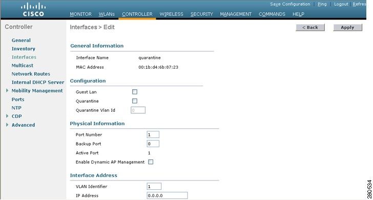
Create the Dynamic Interface on the Wireless LAN Controller
To create and specify settings for a new Dynamic Interface on the Wireless LAN Controller:
Step 1
Step 2
Step 3
Figure 4-3 WLC 4400 Interfaces > Edit Page
Step 4
•
•
Note
•
•
•
•
•
Note
Step 5
Step 6
For more information, refer to the Cisco Wireless LAN Controller Configuration Guide, Release 5.1.
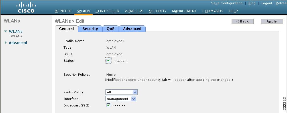
Create the WLAN on the Wireless LAN Controller and Enable Cisco NAC Appliance Integration
To create a new WLAN on the Wireless LAN Controller and enable integration with Cisco NAC Appliance:
Step 1
Step 2
Step 3
Step 4
Step 5
Figure 4-4 WLC 4400 WLANs > Edit Page
Step 6
Caution
Step 7
Step 8
Step 9
Step 10
For more information, refer to the Cisco Wireless LAN Controller Configuration Guide, Release 5.1.
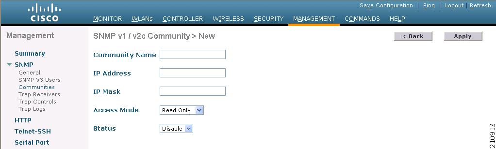
Configure SNMP on the Wireless LAN Controller
To ensure the Wireless LAN Controller is able to receive and process SNMP transmissions from the CAM regarding OOB client machine status in the Cisco NAC Appliance system, you must enable and configure SNMP behavior on the WLC.
To create a new SNMP community and enable SNMP on the WLC:
Step 1
Step 2
Figure 4-5 SNMP v1 / v2c Community > New Page
Step 3
Step 4
Step 5
Step 6
Step 7
Step 8
Step 9
For more information, refer to the Cisco Wireless LAN Controller Configuration Guide, Release 5.1.
Specify the CAM as the SNMP Trap Receiver
Once you enable and configure SNMP on the Wireless LAN Controller, you must also ensure the WLC knows which CAM is receiving SNMP trap messages.
To specify the host name and IP address of the SNMP trap receiver CAM:
Step 1
Figure 4-6 SNMP Trap Receivers > New Page
Step 2
Step 3
Step 4
Step 5
Step 6
Wireless OOB Network Setup/Configuration Worksheet
Table 4-3 summarizes information needed to configure WLCs and the Clean Access Manager.
Configure Wireless LAN Controller Connection on the CAM
This section describes the web admin console configuration steps to implement Wireless OOB. In general, you first configure Group and Wireless LAN Controller profiles, and the CAM's SNMP Receiver settings under OOB Management > Profiles. After the WLC profile is configured, add the new WLC you want to communicate with to the Clean Access Manager's domain under OOB Management > Devices, and ensure the new profile appears in the Devices list.
The configuration sequence is as follows:
1.
2.
4.
6.
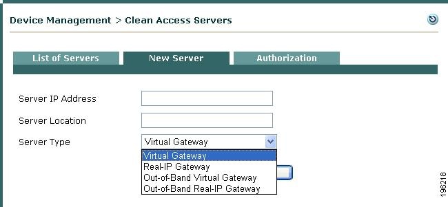
Add a Wireless Out-of-Band Clean Access Server and Configure Environment
Almost all the CAM/CAS configuration for Wireless Out-of-Band deployment is done directly in the OOB Management module of the CAM web console. If your Wireless LAN Controller installation features great enough throughput/bandwidth, you can (and may need to) configure more than one Clean Access Server to handle all of the authentication traffic between wireless client machines and the Cisco NAC Appliance system.
To add a Wireless OOB Clean Access Server to the CAM:
Step 1
Figure 4-7 Add New OOB Server
The Clean Access Server itself must be either In-Band or Out-of-Band. The Clean Access Manager can control both In-Band and Out-of-Band CASs in its domain.
Note
Step 2
Step 3
Step 4
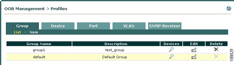
Configure Group Profiles
When you first add a WLC to the Clean Access Manager's domain (under OOB Management > Devices), a Group profile must be applied to add the new WLC. There is a predefined Group profile called default, shown in Figure 4-8. All WLCs are automatically put in the default group when you add them. You can leave this default Group profile setting, or you can create additional Group profiles as needed. If you are adding and managing a large number of WLCs, creating multiple Group profiles allows you to filter which sets of devices to display from the list of WLCs (under OOB Management > Devices > Devices > List).
Figure 4-8 Group Profiles List
Add Group Profile
Step 1
Figure 4-9 New Group
Step 2
Step 3
Step 4
Edit Group Profile
Step 1
Step 2
Figure 4-10 Edit Group
Step 3
Step 4
Note
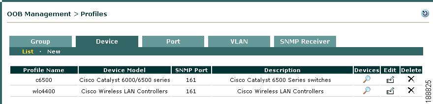
Configure Wireless LAN Controller Profiles
A WLC profile must first be created under OOB Management > Profiles > Device > New, then applied when a new WLC is added. A WLC profile classifies WLCs of the same model and SNMP settings, as shown in Figure 4-11. The WLC profile configures how the CAM learns client Authentication/Access VLAN assignments from the WLC and when to remove Wireless OOB clients from the Online Users list for a WLC of that type.
Figure 4-11 Device Profiles List
The Device profiles list under OOB Management > Profiles > Device > List provides three icons:
•
•
•
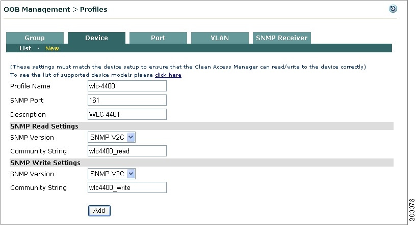
Add Wireless LAN Controller Profile
Use the following steps to add a Wireless LAN Controller profile.
Step 1
Figure 4-12 New Wireless LAN Controller Profile
Step 2
Note
Step 3
Step 4
Note
Step 5
•
•
Step 6
•
•
•
•
Step 7
•
•
Step 8
•
•
•
•
Note
Step 9
Figure 4-13 illustrates a WLC profile defining a Cisco 440 Wireless LAN Controller with the same SNMP settings: SNMP V2c with read community string "wlc4400_read" and write community string "wlc4400_write."
Figure 4-13 Example Wireless LAN Controller Profile
Configure SNMP Receiver
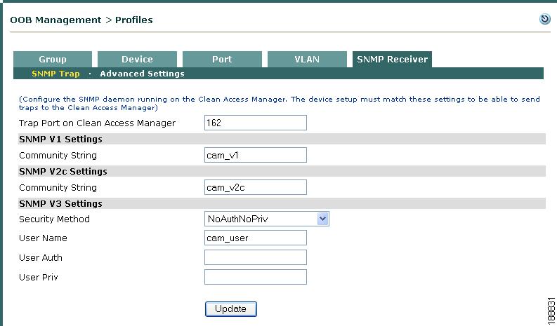
The SNMP Receiver form configures how the SNMP Receiver running on the Clean Access Manager receives and responds to SNMP trap notifications from WLCs when user events occur (such as when a user first logs on to or logs off of the network). The SNMP Receiver configuration on the CAM must match the WLC configuration in order for the WLC to send SNMP traps to the CAM.
SNMP Trap
This page configures settings for the SNMP traps the CAM receives from switches and WLCs. The Clean Access Manager SNMP Receiver can simultaneously support different versions of SNMP (V1, V2c, V3) when controlling groups of switches and/or WLCs in which individual devices may be using different versions of SNMP.
Step 1
Figure 4-14 CAM SNMP Receiver
Step 2
Step 3
Step 4
Step 5
•
•
•
•
Step 6
Add and Manage Wireless LAN Controllers
The pages under the OOB Management > Devices > Devices tab are used to discover and add new switches and WLCs within an IP range, add new switches or WLCs by exact IP address, and manage the list of associated devices. There are two methods to add new managed WLCs:
•
•
Figure 4-15 List of Devices
The list of devices under OOB Management > Devices > Devices > List displays all switches added from the New or Search forms. Wireless LAN Controller entries in the list include the WLC's IP address, MAC address, Description, and WLC Profile. You can sort the entries on the list by Device Group or Device Profile dropdowns, or you can simply type a Device IP and hit Enter to search for a switch by its address. Additionally the List provides one control and two icons:
•
•
Note
Profile links do not apply to WLCs and are "grayed out" in the Devices list for WLC entries.
Add New Wireless LAN Controller
The New page allows you to add WLCs when exact IP addresses are already known.
Step 1
Figure 4-16 Add New Wireless LAN Controller
Step 2
Step 3
Step 4
Step 5
Step 6
Step 7
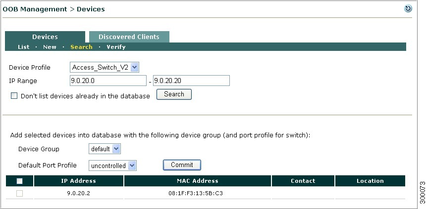
Search New Wireless LAN Controllers
The Search page allows you to discover and add unmanaged switches within an IP range.
Step 1
Figure 4-17 Search Devices
Step 2
Step 3
Step 4
Step 5
Step 6
Note
Step 7
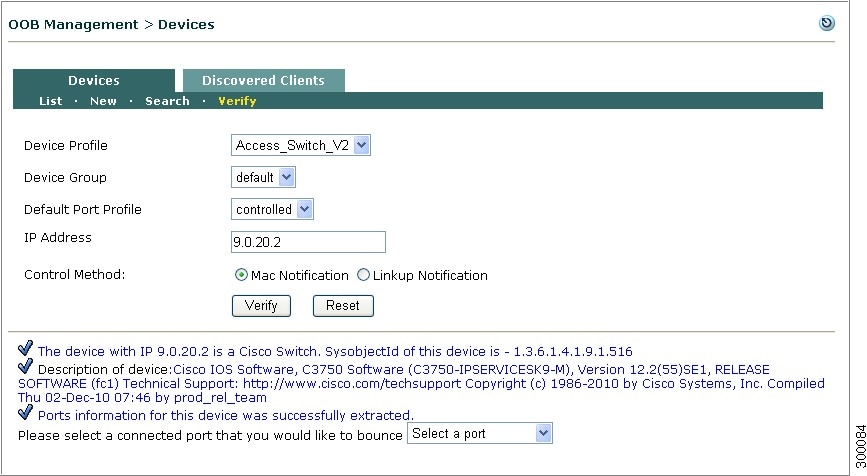
Verify Devices
The Verify page allows you to verify the devices. This utility verifies a device already added to CAM or a new device that is yet to be added to CAM. The device may be a switch or WLC.
Note
Step 1
Figure 4-18 Verify Devices
Step 2
Step 3
Step 4
Step 5
Step 6
Note
•
Note
•
Step 7
The device is verified and the results are displayed at the bottom of the page as shown in Figure 4-19.
Figure 4-19 Verify Devices
- Result
The device status is displayed and you can select a connected port that you would like to bounce from the dropdown.
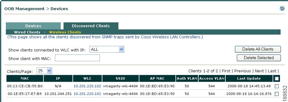
Discovered Wireless Clients
Figure 4-20 shows the OOB Management > Devices > Discovered Clients > Wireless Clients page. The Wireless Clients page lists all clients discovered by the Clean Access Manager via SNMP traps between the CAM and the WLC. The page records the activities of Out-of-Band clients (regardless of VLAN), based on the SNMP trap information that the Clean Access Manager receives.
When a client connects to a WLC and is assigned to the Authentication (Quarantine) VLAN, a trap is sent and the Clean Access Manager creates an entry on the Wireless Clients page. The Clean Access Manager adds a client's MAC address, IP address, associated WLC, Access Point MAC address, and Authentication (Quarantine) and Access VLAN assignments to the Wireless Clients list. Thereafter, the CAM updates the entry as it receives new SNMP trap information for the client.
Removing an entry from the Wireless Clients list clears this status information for the Wireless OOB client from the CAM.
Figure 4-20 Wireless Clients
Elements of the page are as follows:
•
•
•
•
•
•
–
–
–
–
–
–
A value of "N/A" in this column indicates that the VLAN ID for this MAC address is unavailable from the WLC.–
A value of "N/A" in this column indicates the Access VLAN ID is unavailable for the client. For example, if the user is switched to the Authentication VLAN but has never successfully logged into Cisco NAC Appliance (due to wrong user credentials), this machine will never have been assigned to the Access VLAN.–
See Wireless Out-of-Band Users for additional details on monitoring Out-of-Band users.
Config Tab
The Config tab allows you to modify Basic and Group profile settings for a particular Wireless LAN Controller:
Basic
The Basic tab (Figure 4-21) shows the following values configured for the WLC.
Figure 4-21 Config > Basic
•
–
–
–
–
–
•
•
Group
This page displays all the Group Profiles configured in the Clean Access Manager, and the Group Profiles to which the WLC currently belongs. You can add the WLC to other Groups, or you can remove the WLC from a Group Joined. To change the Group membership for all switches, go to OOB Management > Profiles > Group (see Configure Group Profiles).
Figure 4-22 Config > Group
View Wireless Out-of-Band Online Users
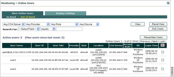
When Out-of-Band is enabled, the Monitoring > View Online Users page displays links for both In-Band and Out-of-Band users and display settings (Figure 4-23). See Out-of-Band Users for details.
Figure 4-23 View Out-of-Band Online Users
Wireless Out-of-Band Users
Wireless OOB User Sessions
The following events trigger Wireless OOB users' disconnection from the Cisco NAC Appliance system:
•
•
•
•
Following log-off, users must undergo authentication again before they are allowed back into the internal network. For additional details, see also Interpreting Event Logs and Manage Certified Devices.
Wireless and Wired OOB User List Summary
Table 3-4 describes the lists used to track Out-of-Band users.