-
Cisco NAC Appliance - Clean Access Manager Configuration Guide, Release 4.9(2)
-
About This Guide
-
Introduction
-
Device Management: Adding Clean Access Servers, Adding Filters
-
Switch Management: Configuring Out-of-Band Deployment
-
Wireless LAN Controller Management: Configuring Wireless Out-of-Band Deployment
-
Configuring User Login Page and Guest Access
-
User Management: Configuring User Roles and Local Users
-
User Management: Configuring Authentication Servers
-
User Management: Traffic Control, Bandwidth, Schedule
-
Configuring Cisco NAC Appliance for Agent Login and Client Posture Assessment
-
Cisco NAC Appliance Agents
-
Monitoring and Troubleshooting Agent Sessions
-
Configuring Network Scanning
-
Monitoring Event Logs
-
Administering the CAM
-
Error and Event Log Messages
-
API Support
-
MIB Support
-
Open Source License Acknowledgements
-
 Feedback
Table Of Contents
User Management: Configuring Authentication Servers
Adding an Authentication Provider
Add a FIPS 140-2 Compliant RADIUS Auth Provider Using an ACS Server
RADIUS Challenge-Response Impact On the Agent
Configure LDAP Server with Simple Authentication
Configure LDAP Server with GSSAPI Authentication
Active Directory Single Sign-On (SS0)
Implementing Windows NetBIOS SSO
Configuring Authentication Cache Timeout (Optional)
Authenticating Against a Backend Active Directory
Map Users to Roles Using Attributes or VLAN IDs
Restore Factory Default Settings
Add Data to Login, Logout or Shared Events
Add New Entry (Login Event, Logout Event, Shared Event)
User Management: Configuring Authentication Servers
This chapter describes how to set up external authentication sources, configure Active Directory Single Sign-On (SSO), VLAN ID or attribute-based auth server mapping rules, and RADIUS accounting. Topics are as follows:
•
Adding an Authentication Provider
•
•
•
For details on AD SSO, see the "Configuring Active Directory Single Sign-On (AD SSO)" chapter in the Cisco NAC Appliance - Clean Access Server Configuration Guide, Release 4.9(2).
For details on creating and configuring the web user login page, see Chapter 5 "Configuring User Login Page and Guest Access."
For details on configuring user roles and local users, see Chapter 6 "User Management: Configuring User Roles and Local Users."
For details on configuring traffic policies for user roles, see Chapter 8 "User Management: Traffic Control, Bandwidth, Schedule."
Overview
By connecting the Clean Access Manager to external authentication sources, you can use existing user data to authenticate users and administrator users in the untrusted network. Cisco NAC Appliance supports several authentication provider types for the following two cases:
•
•
Working with Existing Backend Authentication Servers
When working with existing backend authentication servers, Cisco supports the following authentication protocol types:
•
•
•
•
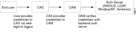
When using this option, the CAM is the authentication client which communicates with the backend auth server. Figure 7-1 illustrates the authentication flow.
Figure 7-1 Cisco NAC Appliance Authentication Flow with Backend Auth Server
Currently, it is required to use RADIUS, LDAP, Windows NT, or Kerberos auth server types if you want to enable Cisco NAC Appliance system features such as:
•
•
•
Note
Working with Transparent Auth Mechanisms
When using this option, Cisco supports the following authentication protocol types:
•
•
•
•
Depending on the protocol chosen, the Clean Access Server sniffs traffic relevant to the authentication source flowing from the end user machine to the auth server (for example, Windows logon traffic for the Windows NetBIOS SSO auth type). The CAS then uses or attempts to use that information to authenticate the user. In this case, the user does not explicitly log into the Cisco NAC Appliance system (via web login or Agent).
Note
Local Authentication
You can set up any combination of local and external authentication mechanisms for both users and Cisco NAC Appliance administrators. Typically, external authentication sources are used for general users, while local authentication (where users are validated internally to the CAM) is used for test users, guests, or other types of users with limited network access. For details on using local authentication for guest access, see Guest User Access.
Providers
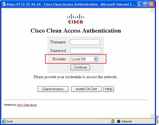
A provider is a configured authentication source. You can configure the providers you set up to appear in the Provider dropdown menu of the web login page (Figure 7-2) and Agent to allow users to choose the domain in which to be authenticated.
Figure 7-2 Provider Field in Web Login Page
Mapping Rules
You can set up role assignment for users based on the authentication server. For all auth server types, you can create mapping rules to assign users to roles based on VLAN ID. For LDAP and RADIUS auth servers, you can additionally map users into roles based on attribute values passed from the authentication server.
FIPS 140-2 Compliance
For LDAP over GSSAPI and Kerberos functions with FIPS-compliant CAMs/CASs, you must ensure that hosts are running Windows 2008 Server to support secure authentication sessions between external resources and FIPS-compliant appliances.
You can configure a FIPS 140-2 compliant external RADIUS Authentication Provider type by setting up a secure IPSec tunnel between your Cisco NAC Appliance system and Cisco ACS 4.x in a Windows environment running Windows Server 2003 or 2008.
Adding an Authentication Provider
The following are the general steps to add an authentication server to the Clean Access Manager:
Step 1
Step 2
Step 3
Step 4
Step 5
Step 6
Step 7
The new authentication source appears under User Management > Auth Servers > List.
•
•
Specific parameters to add each auth server type are described in the following sections:
•
•
Specific parameters to add each auth server type are described in the following sections:
•
Note
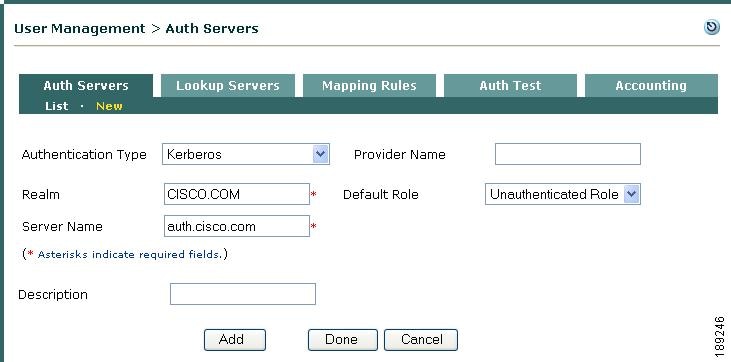
Kerberos
Note
Note
Step 1
Step 2
Figure 7-3 Add Kerberos Auth Server
Step 3
Step 4
Step 5
Step 6
Step 7
Step 8
Note
While running Windows 2008 AD Server at 2003 Server functional level, if you face issues, try the following:
Run KTPass to allow multiple algorithms for new service account.
ktpass -princ newadsso/[adserver.]domain.com@DOMAIN.COM -mapuser newadsso -pass
PasswordText -out c:\newadsso.keytab -ptype KRB5_NT_PRINCIPAL
Note
After running the ktpass command above, manually modify two files on the CAM as follows:
–
[libdefaults]kdc_timeout = 20000default_tkt_enctypes = RC4-HMACdefault_tgs_enctypes = RC4-HMACpermitted_enctypes = RC4-HMAC–
Search for CATALINA_OPTS.
Add -DKRB_OVERRIDE=true to the value of CATALINA_OPTS.
For example:
Old value: CATALINA_OPTS="-server ..."New Value: CATALINA_OPTS="-server ... -DKRB_OVERRIDE=true"
Note
Restart the CAM by entering the service perfigo stop and service perfigo start commands. See also Cisco NAC Appliance - Clean Access Server Configuration Guide, Release 4.9(2) for complete details.
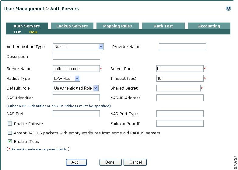
RADIUS
The RADIUS authentication client in the Clean Access Manager can support failover between two RADIUS servers. This allows the CAM to attempt to authenticate against a pair of RADIUS servers, trying the primary server first and then failing over to the secondary server if it is unable to communicate with the primary server. See the Enable Failover and Failover Peer IP field descriptions below for details.
Note
Step 1
Step 2
Figure 7-4 Add RADIUS Auth Server
Step 3
Step 4
Step 5
Step 6
Step 7
Step 8
Step 9
Step 10
Step 11
Note
Step 12
Step 13
Step 14
Step 15
Step 16
Step 17
Step 18
Step 19
Note
Add a FIPS 140-2 Compliant RADIUS Auth Provider Using an ACS Server
You can configure a FIPS 140-2 compliant external RADIUS Auth Provider type by setting up IPSec communication between your Cisco NAC Appliance system and Cisco ACS 4.x in a Windows environment running Windows Server 2003 or 2008. There are two primary stages to this task:
•
Import Certificates in Windows
Step 1
Step 2
Step 3
Step 4
Step 5
Step 6
Step 7
Step 8
Step 9
Step 10
Step 11
openssl pkcs12 -export -in cert.pem -inkey key.pem -out ACSCert.p12Step 12
You will also need to use this password when you import the ACS certificate on in Windows.
Step 13
Step 14
Step 15
Step 16
Step 17
Step 18
Step 19
Set Up the IPSec Tunnel
Note
Step 1
Step 2
Step 3
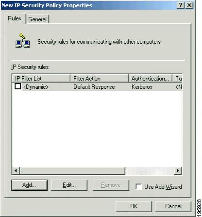
Figure 7-5 New IP Security Policy
Step 4
Step 5
Step 6
Step 7
Step 8
Step 9
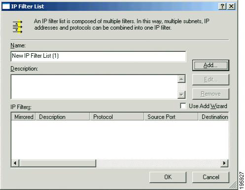
Figure 7-6 IP Filter List
Step 10
Step 11
Step 12
Step 13
Step 14
Step 15
Step 16
Step 17
Step 18
Step 19
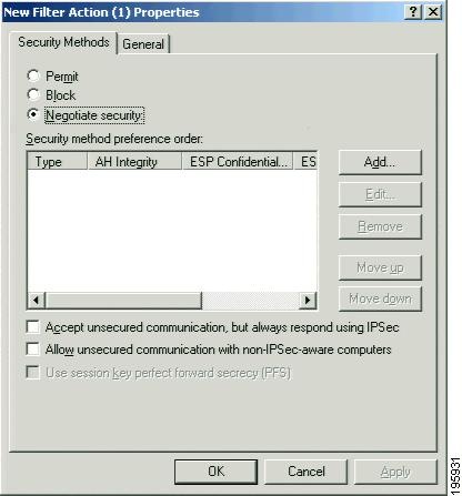
Figure 7-7 New Filter Action
Step 20
Step 21
Step 22
Step 23
Step 24
•
•
•
Step 25
Step 26
Step 27
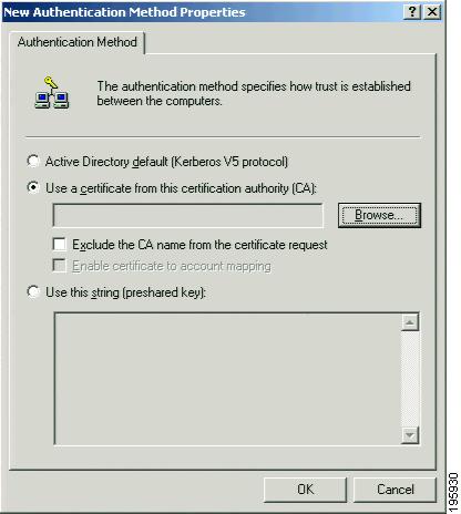
Figure 7-8 Authentication Methods
Step 28
Step 29
Figure 7-9 Use a certificate from this certification authority (CA)
Step 30
Step 31
Step 32
Step 33
Step 34
Step 35
Step 36
Step 37
RADIUS Challenge-Response Impact On the Agent
If you configure the Clean Access Manager to use a RADIUS server to validate remote users, the end-user Agent login session can accommodate extra authentication challenge-response dialogs not available in other dialog sessions—beyond the standard user ID and password. This additional interaction is due to the user authentication profile on the RADIUS server, itself, and does not require any additional configuration on the Clean Access Manager. For example, the RADIUS server profile configuration may feature an additional authentication challenge like verifying a token-generated PIN or other user-specific credentials in addition to the standard user ID and password. In this case, one or more additional login dialog screens may appear as part of the login session. For details, refer to RADIUS Challenge-Response Cisco NAC Agent Dialogs.
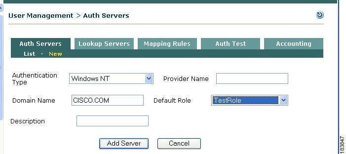
Windows NT
Note
•
1.
2.
Figure 7-10 Add Windows NT Auth Server
3.
4.
5.
6.
7.
LDAP
Note
An LDAP auth provider in the Clean Access Manager can be used to authenticate users against a Microsoft Active Directory server. See Authenticating Against a Backend Active Directory for details. You can configure the LDAP server to use one of two authentication mechanisms:
•
•
Note
In Cisco NAC Appliance, you can configure one LDAP auth provider using the GSSAPI authentication method and one Kerberos auth provider, but only one of the two can be active at any time. See Kerberos for more information.
For LDAP over GSSAPI functions with FIPS 140-2 compliant CAMs, you must ensure that hosts are running Windows 2008 Server to support secure authentication sessions between external resources and FIPS-compliant appliances.
Note
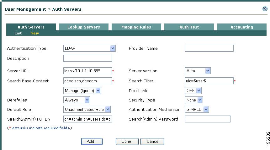
Configure LDAP Server with Simple Authentication
Step 1
Step 2
Figure 7-11 Add LDAP Auth Server—SIMPLE Authentication Mechanism
Step 3
Step 4
Step 5
ldap://<directory_server_name>:<port_number>If no port number is specified, 389 is assumed.
Note
You can add redundancy for LDAP Authentication servers by entering multiple LDAP URLs in the Server URL field separated by a space, for example:ldap://ldap1.abc.com ldap://ldap2.abc.com ldap://ldap3.abc.com
If the first LDAP server listed does not respond within 15 seconds, the CAM then attempts to authenticate using the alternate LDAP server(s) in the list. Every LDAP authentication request is passed to the first server specified in the list by default. You can only input 128 characters in this field, thus limiting the number of redundant servers you can specify.
Step 6
Step 7
Step 8
Step 9
Step 10
Step 11
Step 12
Note
Step 13
Step 14
Step 15
cn= jane doe, cn=users, dc=cisco, dc=comStep 16
Step 17
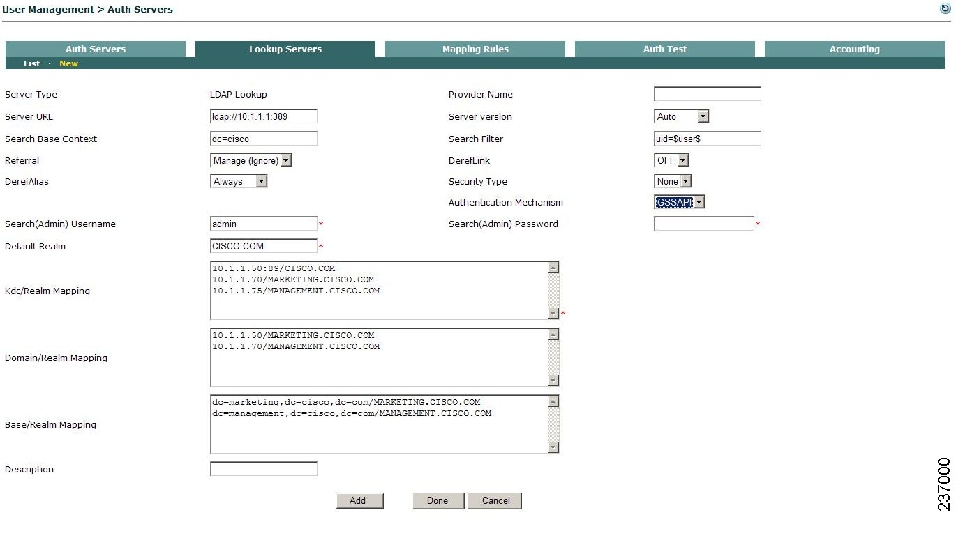
Configure LDAP Server with GSSAPI Authentication
Note
Note
Step 1
Step 2
Figure 7-12 Add LDAP Auth Server—GSSAPI Authentication Mechanism
Step 3
Step 4
Step 5
ldap://<directory_server_name>:<port_number>If no port number is specified, 389 is assumed.
Note
You can add redundancy for LDAP Authentication servers by entering multiple LDAP URLs in the Server URL field separated by a space, for example:ldap://ldap1.abc.com ldap://ldap2.abc.com ldap://ldap3.abc.com
If the first LDAP server listed does not respond within 15 seconds, the CAM then attempts to authenticate using the alternate LDAP server(s) in the list. Every LDAP authentication request is passed to the first server specified in the list by default. You can only input 128 characters in this field, thus limiting the number of redundant servers you can specify.
Step 6
Step 7
Step 8
Step 9
Step 10
Step 11
Step 12
Note
Step 13
Step 14
Note
Step 15
Step 16
Step 17
Step 18
Step 19
Note
Step 20
Step 21
Step 22
Active Directory Single Sign-On (SS0)
See the "Configuring Active Directory Single Sign-On (AD SSO)" chapter in the Cisco NAC Appliance - Clean Access Server Configuration Guide, Release 4.9(2) for complete details.
Windows NetBIOS SSO
Note
In Windows NetBIOS SSO authentication (formerly known as "Transparent Windows"), the CAS sniffs relevant Windows login packets from the end-user machine to the domain controller to determine whether or not the user is logged in successfully. If Windows NetBIOS SSO authentication is enabled and the CAS successfully detects login traffic, the user is logged into the Cisco NAC Appliance system without having to explicitly login through the web login page or Agent.
With Windows NetBIOS SSO, only authentication can be done—posture assessment, quarantining, remediation, do not apply. However, the user only needs to perform Ctrl-Alt-Dlt to login.
Note
Implementing Windows NetBIOS SSO
Implementing Windows NetBIOS SSO login involves the following steps:
1.
2.
a.
b.
See section "Enable Windows NetBIOS SSO" of the Cisco NAC Appliance - Clean Access Server Configuration Guide, Release 4.9(2) for details.
3.
Note
Add Windows NetBIOS SSO Auth Server
1.
2.
Figure 7-13 Add Windows NetBIOS SSO Auth Server
3.
4.
5.
6.
Cisco VPN SSO
Cisco NAC Appliance enables administrators to deploy the CAS In-Band behind a VPN concentrator, or router, or multiple routers. Cisco NAC Appliance supports multi-hop Layer 3 In-Band deployment by allowing the CAM and CAS to track user sessions by unique IP address when users are separated from the CAS by one or more routers. With Layer 2-connected users, the CAM/CAS continue to manage these user sessions based on the user MAC addresses, as before.
Note
•
•
•
•
•
You can configure Cisco NAC Appliance to perform VPN SSO via a Cisco ASA in a FIPS-compliant network deployment. For detailed configuration information, see the "Configure VPN SSO in a FIPS 140-2 Compliant Deployment" section of the Cisco NAC Appliance - Clean Access Server Configuration Guide, Release 4.9(2).
Cisco NAC Appliance provides integration with Cisco VPN concentrators and can enable SSO capability for VPN users, using RADIUS Accounting information. The Clean Access Server can acquire the client's IP address from either Framed_IP_address or Calling_Station_ID RADIUS attributes for SSO purposes.
•
Note
•
•
Figure 7-14 illustrates the login and posture assessment process for a VPN user using the Agent with Single Sign-On. Note that the initial download of the Agent must be performed via the VPN connection.
Figure 7-14 Agent with SSO for VPN Users
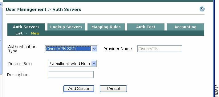
Add Cisco VPN SSO Auth Server
To enable SSO for Cisco VPN concentrator users, add a Cisco VPN SSO auth server:
Step 1
Step 2
Figure 7-15 Add Cisco VPN Auth Server
Step 3
Step 4
Step 5
Step 6
Make sure you have completed configuration under Device Management > CCA Servers > List of Servers > Manage [CAS_IP] > Authentication > VPN Auth. For complete details on configuring the Clean Access Server for VPN concentrators, see the Cisco NAC Appliance - Clean Access Server Configuration Guide, Release 4.9(2).
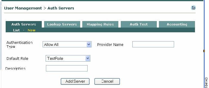
Allow All
The AllowAll option is a special authentication type that provides an alternative to the Guest Access login button feature. It allows users to type in any credential to login (e.g., an email address for user name and/or password) but does not validate the credentials. This option can be used when administrators want to capture limited information on who is logging in (such as a list of email addresses). The identifier the user submits in the login page will appear as the User Name in the Online Users page while the user is logged in. In this case, administrators should also modify the Username Label button label on the login page to reflect the type of value they want users to enter as a credential. See Guest User Access for additional details.
Note
Step 1
Step 2
Figure 7-16 Allow All Auth Server Type
Step 3
Step 4
Step 5
Step 6
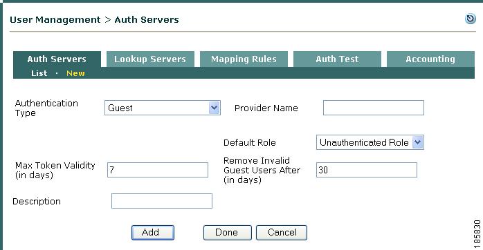
Guest
The Guest option is very similar in implementation and application to the Allow All auth server type and it serves as a useful alternative to guest users simply logging in via the existing guest access button on the web login page. Like the Allow All auth server type, the Guest option allows users to type in any credential to login (e.g., an Email address for user name and/or password) but does not validate the credentials, but also enables you to collect other required or optional information not available in the Allow All function. For example, you can require users to supply a contact phone number and birth date before they are allowed to access the network as a guest user. The identifier a user submits in the login page appears in the Online Users and User Management > Local Users > Guest Users pages while the user is logged in.
Note
To configure a Guest authentication server type:
Step 1
Step 2
Figure 7-17 Guest Auth Server Type
Step 3
Step 4
Step 5
Step 6
Tip
Step 7
Step 8
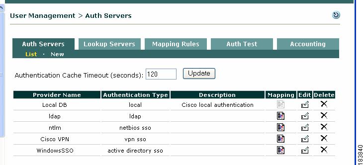
Configuring Authentication Cache Timeout (Optional)
For performance reasons, the Clean Access Manager caches the authentication results from user authentication for 2 minutes by default. The Authentication Cache Timeout control on the Auth Server list page allows administrators to configure the number of seconds the authentication result will be cached in the CAM. When a user account is removed from the authentication server (LDAP, RADIUS, etc.), administrators can restrict the time window a user can login again into Cisco NAC Appliance by configuring the Authentication Cache Timeout.
Step 1
Figure 7-18 List Auth Servers
Step 2
Note
Step 3
Authenticating Against a Backend Active Directory
Several types of authentication providers in the Clean Access Manager can be used to authenticate users against an Active Directory server, Microsoft's proprietary directory service. These include Windows NT (NTLM), Kerberos, and LDAP (preferred).
If using LDAP to connect to the AD server, the Search(Admin) Full DN (distinguished name) can be the DN of an AD administrator or user account and the first CN (common name) entry should be an AD user with read privileges.
Note
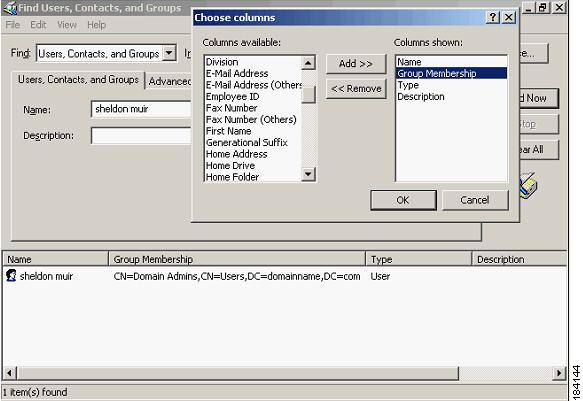
AD/LDAP Configuration Example
The following illustrates a sample configuration using LDAP to communicate with the backend Active Directory:
1.
2.
Figure 7-19 Find Group Membership within Active Directory
3.
4.
5.
Figure 7-20 Example New LDAP Server for AD
6.
a.
b.
Note
c.
d.
e.
f.
g.
h.
7.
8.
Note
Map Users to Roles Using Attributes or VLAN IDs
The Mapping Rules forms can be used to map users into user role(s) based on the following parameters:
•
Note
•
Note
For more information, see the following Microsoft Knowledge Base articles:
http://support.microsoft.com/kb/275523
http://support.microsoft.com/kb/321360For example, if you have two sets of users on the same IP subnet but with different network access privileges (e.g. wireless employees and students), you can use an attribute from an LDAP server to map one set of users into a particular user role. You can then create traffic policies to allow network access to one role and deny network access to other roles. (See Chapter 8 "User Management: Traffic Control, Bandwidth, Schedule" for details on traffic policies.)
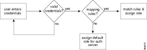
Cisco NAC Appliance performs the mapping sequence as shown in Figure 7-21.
Figure 7-21 Mapping Rules
Note
Cisco NAC Appliance allows the administrator to specify complex Boolean expressions when defining mapping rules for Kerberos, LDAP and RADIUS authentication servers. Mapping rules are broken down into conditions and you can use Boolean expressions to combine multiple user attributes and multiple VLAN IDs to map users into user roles. Mapping rules can be created for a range of VLAN IDs, and attribute matches can be made case-insensitive. This allows multiple conditions to be flexibly configured for a mapping rule.
A mapping rule comprises an auth provider type, a rule expression, and the user role into which to map the user. The rule expression comprises one or a combination of conditions the user parameters must match to be mapped into the specified user role. A condition is comprised of a condition type, a source attribute name, an operator, and the attribute value against which the particular attribute is matched.
To create a mapping rule you first add (save) conditions to configure a rule expression, then once a rule expression is created, you can add the mapping rule to the auth server for the specified user role.
Mapping rules can be cascading. If a source has more than one mapping rule, the rules are evaluated in the order in which they appear in the mapping rules list. The role for the first positive mapping rule is used. Once a rule is met, other rules are not tested. If no rule is true, the default role for that authentication source is used.
Configure Mapping Rule
1.
•
•
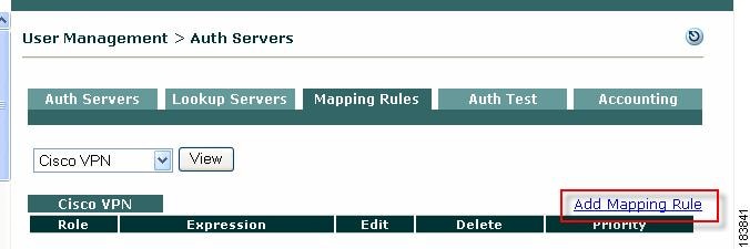
Figure 7-22 List of Auth Servers
Figure 7-23 Mapping for Cisco VPN Auth Type
2.
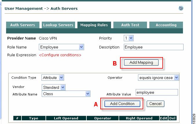
Figure 7-24 Example Add Mapping Rule (Cisco VPN)
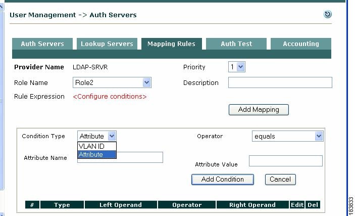
Configure Conditions for Mapping Rule (A)
•
•
–
–
–
3.
–
–
Note
For more information, see the following Microsoft Knowledge Base articles:
http://support.microsoft.com/kb/275523
http://support.microsoft.com/kb/321360–
4.
–
–
Note
–
5.
6.
–
–
–
–
–
–
7.
–
–
–
Note
8.
Add Mapping Rule to Role (B)
Add the mapping rule (step B in Figure 7-24) after you have configured and added the condition(s).
9.
10.
11.
12.
13.
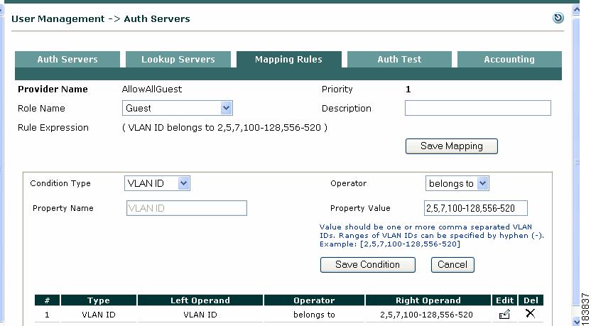
Figure 7-25 Example Add VLAN ID Mapping Rule
Figure 7-26 Example Add LDAP Mapping Rule (Attribute)
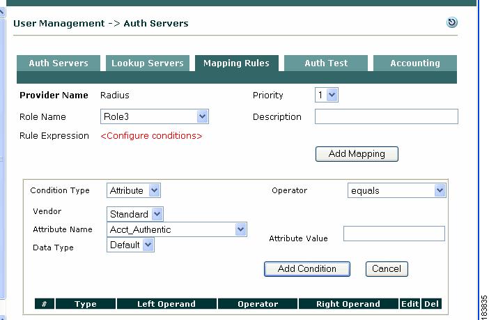
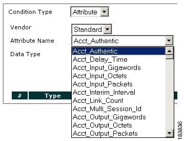
Figure 7-27 Example Add RADIUS Mapping Rule (Attribute)
.
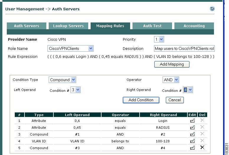
Figure 7-28 Example Compound Condition Mapping Rules
Editing Mapping Rules
Priority—To change the priority of a mapping rule later, click the up/down arrow next to the entry in the User Management > Auth Servers > List. The priority determines the order in which the rules are tested. The first rule that evaluates to true is used to assign the user to a role.
Edit—Click the Edit icon next to the rule to modify the mapping rule, or delete conditions from the rule. Note that when editing a compound condition, the conditions below it (created later) are not displayed. This is to avoid loops.
Delete—Click the delete icon next to the Mapping Rule entry for an auth server to delete that individual mapping rule. Click the delete icon next to a condition on the Edit mapping rule form to remove that condition from the Mapping Rule. Note that you cannot remove a condition that is dependent on another rule in a compound statement. To delete an individual condition, you have to delete the compound condition first.
Figure 7-29 CiscoVPN—Standard Attribute Names
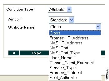
Figure 7-30 RADIUS—Standard Attribute Names
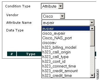
Figure 7-31 RADIUS—Cisco Attribute Names
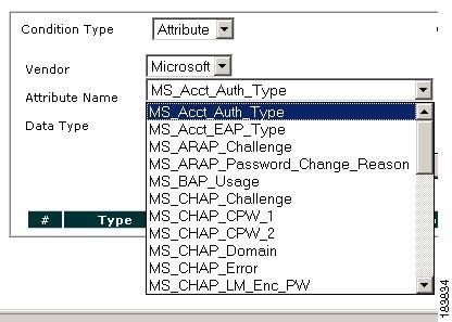
Figure 7-32 RADIUS—Microsoft Attribute Names
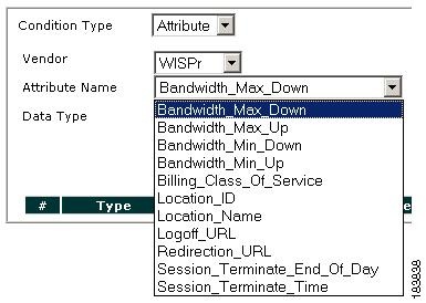
Figure 7-33 RADIUS—WISPr (Wireless Internet Service Provider roaming) Attribute Names
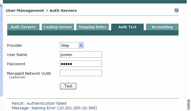
Auth Test
The Auth Test tab is allows you to test Kerberos, RADIUS, Windows NT, LDAP, and AD SSO authentication providers you configured against actual user credentials, and lists the role assigned to the user. Error messages are provided to assist in debugging authentication sources, particularly LDAP and RADIUS servers.
To use the Auth Test function to test AD SSO authentication in Cisco NAC Appliance, you must perform the following set-up steps, as described in the "Configuring Active Directory Single Sign-On (AD SSO)" chapter of the Cisco NAC Appliance - Clean Access Server Configuration Guide, Release 4.9(2), before testing AD SSO server authentication:
1.
2.
Tip
Note
To test authentication:
Step 1
Step 2
Step 3
Figure 7-34 Auth Test
Authentication Successful
For any provider type, the Result "Authentication successful" and Role of the user are displayed when the auth test succeeds.
For LDAP/RADIUS servers, when authentication is successful and mapping rules are configured, the attributes/values specified in the mapping rule are also displayed if the auth server (LDAP/RADIUS) returns those values. For example:
Result: Authentication successfulRole: <role name>Attributes for Mapping:<Attribute Name>=<Attribute value>Authentication Failed
When authentication fails, a Message displays along with the "Authentication failed" result. Table 7-1 illustrates some example authentication test failure messages.
Note
RADIUS Accounting
The Clean Access Manager can be configured to send accounting messages to a RADIUS accounting server. The CAM sends a Start accounting message when a user logs into the network and sends a Stop accounting message when the user logs out of the system (or is logged out or timed out). This allows for the accounting of user time and other attributes on the network.
You can also customize the data to be sent in accounting packets for login events, logout events, or shared events (login and logout events).
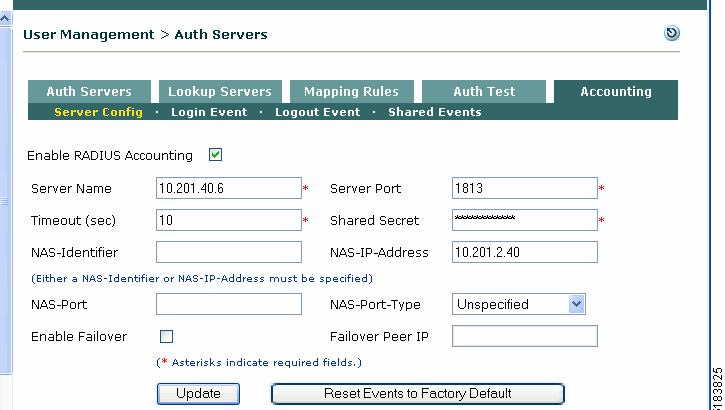
Enable RADIUS Accounting
Step 1
Figure 7-35 RADIUS Accounting Server Config Page
Step 2
Step 3
•
•
•
•
•
•
Note
•
•
•
•
Step 4
Restore Factory Default Settings
The Clean Access Manager can be restored to the factory default accounting configuration as follows:
1.
2.
3.
4.
Add Data to Login, Logout or Shared Events
For greater control over the data that is sent in accounting packets, you can add or customize the RADIUS accounting data that is sent for login events, logout events, or shared events (data sent for both login and logout events).
Data Fields
The following data fields apply to all events (login, logout, shared):
•
•
•
•
•
•
•
•
•
•
•
•
•
•
•
•
•
Note
•
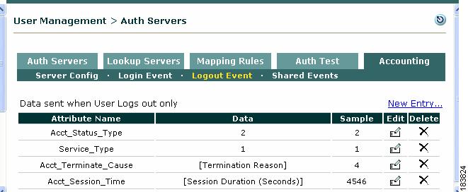
Logout Event Data Fields
The following four data fields apply to logout events only and are not sent for login or shared events:
•
•
•
•
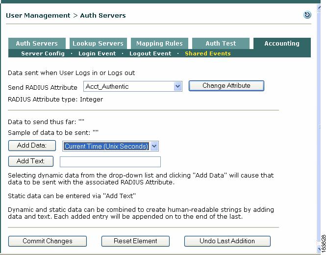
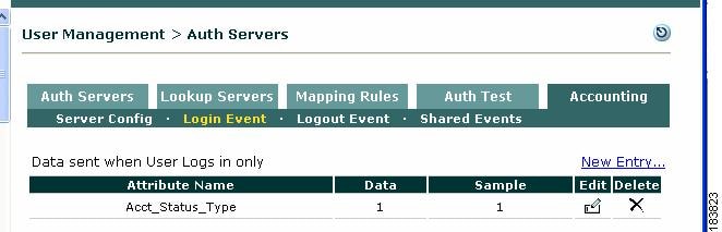
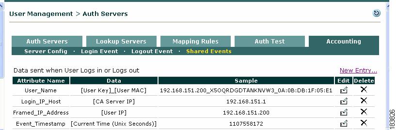
Add New Entry (Login Event, Logout Event, Shared Event)
To add new data to a RADIUS attribute for a shared event:
The following steps describe how to configure a RADIUS attribute with customized data. The steps below describe a shared event. The same process applies for login and logout events.
1.
2.
3.
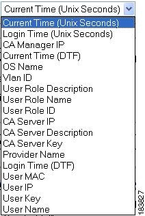
Figure 7-36 New Shared Event
Figure 7-37 RADIUS Attribute Dropdown Menu
4.
5.
6.
–
–
–
User: [User Name] logged in at: [Login Time DTF] from CA Server [CA Server Description]See also Figure 7-38, Figure 7-39, and Figure 7-40 show examples of Login, Logout, and Shared events, respectively. for additional details.
7.
8.
9.
10.
Figure 7-38, Figure 7-39, and Figure 7-40 show examples of Login, Logout, and Shared events, respectively.
Figure 7-38 Login Events
Figure 7-39 Logout Events
Figure 7-40 Shared Events