Feedback
Table Of Contents
Inline Posture Known Limitations
Understanding the Role of Inline Posture
Planning an Inline Posture Deployment
About Inline Posture Configuration
Choosing an Inline Posture Operating Mode
Best Practices for Inline Posture
Standalone Mode or High Availability
Inline Posture High Availability
Inline Posture Guidelines for Distributed Deployment
Deploying an Inline Posture Node
Configuring Inline Posture for High Availability
Configuring a High Availability Pair
Syncing an Inline Posture Node
Adding Inline Posture as a RADIUS Client
Monitoring an Inline Posture Node
Removing an Inline Posture Node from Deployment
Setting Up Inline Posture
This chapter describes how to set up and configure Inline Posture nodes in standalone mode, or as a high availability pair, and covers the following topics:
•
Inline Posture Known Limitations
•
•
•
•
•
•
•
Inline Posture Known Limitations
This section describes known limitations for Inline Posture in Cisco ISE, Release 1.0.
•
•
•
•
For more information on these and other known issues, see the Known Issues section of the Release Notes for the Cisco Identity Services Engine, Release 1.0.
Understanding the Role of Inline Posture
An Inline Posture node is a gatekeeper that enforces access policies and handles change of authorization (CoA) requests. An Inline Posture node is positioned behind the network access devices on your network that are unable to accommodate CoA, such as wireless LAN controllers (WLC) and virtual private network (VPN) devices.
After the initial authentication of a client (using EAP/802.1x and RADIUS), the client must still go through posture assessment. The posture assessment process determines whether the client should be restricted, denied, or allowed full access to the network. When a client accesses the network through a WLC or VPN device, Inline Posture is responsible for the policy enforcement and CoA that these devices are unable to accommodate.
Inline Posture Policy Enforcement
Inline Posture uses RADIUS proxy and URL redirect capabilities in the control plane to manage data plane traffic for endpoints. As a RADIUS proxy, Inline Posture is able to tap into RADIUS sessions between network access devices (NADs) and RADIUS servers. NADs can open full gate to client traffic. However, Inline Posture opens only enough to allow limited traffic from clients. The restricted bandwidth allows clients the ability to have an agent provisioned, have posture assessed, and have remediation done. This restriction is accomplished by downloading and installing DACLs that are tailored for specific client flow.
Upon full compliance, a CoA is sent to the Inline Posture node by the Policy Service ISE node, and full gate is opened by the Inline Posture node for the compliant client endpoint. The RADIUS proxy downloads the full-access DACL, installs it, and associates the client IP address to it. The installed DACL can be common for a number of user groups, so that duplicate downloads are not necessary as long as the DACL content does not change at the Cisco ISE servers.
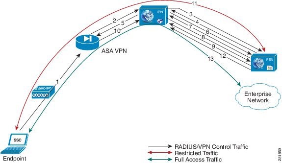
Figure 10-1 illustrates the Inline Posture policy enforcement process. This example shows the flow for WLC enforcement for traffic to the Policy Service ISE node. However, the access steps are similar for an inline deployment with VPN gateways.
Figure 10-1 Inline Posture Policy Enforcement Flow
The Inline Posture policy enforcement flow illustrated in Figure 10-1 follows these steps:
1.
2.
3.
4.
There can be a number of RADIUS transactions between the Endpoint, WLC, Inline Posture node, and the Cisco ISE RADIUS server before the Access-Accept message is sent. The process described in this example has been simplified for the sake of brevity.
5.
6.
7.
8.
9.
There may be a number of transactions before the complete ACL is downloaded, especially if the ACL is too large for one transaction.
10.
The actual data traffic from the endpoint may arrive at the Inline Posture untrusted side before the Accounting-Start message is received by the Inline Posture node. Upon receiving the RADIUS Accounting-Start message, the Inline Posture node learns the IP address of the endpoint involved in the session and associates the endpoint with the ACL (downloaded and installed earlier in the session). The initial profile for this client endpoint could be restrictive, to posture the client before being given full access.
11.
12.
13.
A RADIUS stop message for a given session that is issued from the WLC, resets the corresponding endpoint access at the Inline Posture node.
In a deployment, such as outlined in the example, when more endpoints connect to the wireless network they are likely to fall into one of the identity groups that already have authenticated and authorized users connected to the network.
For instance, there may be an employee, executive, and guest that have been granted access through the outlined steps. This situation means that the respective restrictive or full-access profiles for those ID groups have already been installed on the Inline Posture node. The subsequent endpoint authentication and authorization uses the existing installed profiles on the Inline Posture node, unless the original profiles have been modified at the Cisco ISE policy configuration. In the latter case, the modified profile with ACL is downloaded and installed on the Inline Posture node, replacing the previous version.
Trusted and Untrusted Interfaces
The following terminology plays a significant role in an Inline Posture deployment. For this reason, it is important that you understand the definitions as they relate to Inline Posture:
•
•
Inline Posture Dedicated Nodes
Unlike other persona services, Inline Posture is unable to share a node with other services. This inability to share a node means that Inline Posture must be a dedicated node that is registered to the primary Administration ISE node on your network.
Cisco ISE allows you to have up to two Inline Posture nodes configured as an active-standby pair for high availability.
For information on Cisco ISE distributed deployments, see Chapter 9, "Setting Up Cisco ISE in a Distributed Environment."
Planning an Inline Posture Deployment
Before you begin configuring Inline Posture for your network, you should understand the Inline Posture operating modes, deployment options, as well as the basics of filters and managed subnets as they apply to Inline Posture.
This section provides information on the following topics:
•
•
•
•
•
•
•
Note
About Inline Posture Configuration
Inline Posture is a dedicated node registered to the Administration ISE node. You configure Inline Posture from the administration console, and that configuration is then pushed to the Inline Posture node. A copy of the configuration is stored locally in the administration database. Registration results in the Inline Posture node being rebooted.
If you have an Inline Posture high availability (HA) pair, the configuration automatically pushes to both Inline Posture nodes. If the secondary node is down during a configuration change, you can click a database sync button on the primary node that automatically applies the latest configuration to the secondary node when it comes up. A local database maintains the configurations.
Note
Choosing an Inline Posture Operating Mode
The Inline Posture operating mode you choose depends largely on the architecture of your existing network. However, this choice sets a precedent for many of the other configuration options you have to specify for the deployment. For this reason, it is important that you understand the functions of each of the following Inline Posture operating modes:
•
•
•
Bridged mode and router mode are discussed in greater detail throughout the rest of this section.
Inline Posture Router Mode
In router mode, the Inline Posture node operates as a Layer 3 router, and becomes the default gateway for the untrusted network with its managed clients. All traffic between the untrusted and trusted network passes through the Inline Posture node, which applies the IP filtering rules, access policies, and other traffic-handling mechanisms you decide to configure.
When you configure Inline Posture in router mode, you need to specify the IP addresses of its two interfaces:
•
•
The trusted and untrusted addresses should be on different subnets. Inline Posture can manage one or more subnets, with the untrusted interface acting as a gateway for the managed subnets.
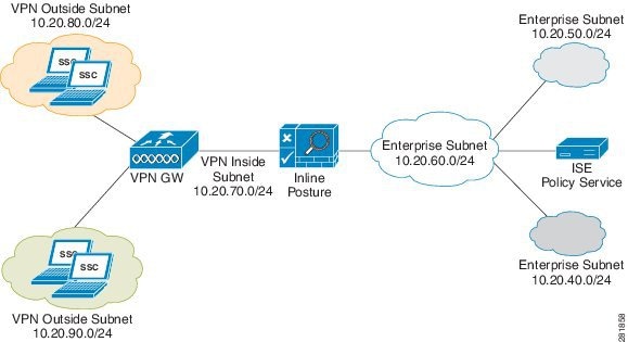
Figure 10-2, illustrates an Inline Posture router mode configuration. In the following router mode example, Inline Posture is a hop for the client traffic from the VPN gateway (GW) en route to the Policy Service ISE node. Inline Posture requires that static routes be configured for subnets 10.20.80.0/24 and 10.20.90.0/24 toward the VPN gateway, just like any other router. The enterprise router on the trusted side of the network also requires that the static routes are configured for the same subnets toward the Inline Posture node.
Figure 10-2 Inline Posture Router Mode Configuration
Inline Posture Bridged Mode
In bridged mode, the Inline Posture node operates as a standard Ethernet bridge. This configuration is typically used when the untrusted network already has a gateway, and you do not want to change the existing configuration.
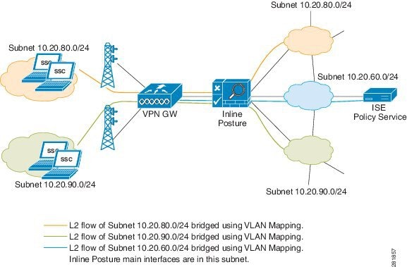
Figure 10-3 shows the Inline Posture node acting as a bridge for the Layer 2 client traffic from the WLC into the Cisco ISE network, managed by the Policy Service ISE node. In this configuration, Inline Posture requires subnet entries for the 10.20.80.0/24 and 10.20.90.0/24 subnets to be able to respond to and send Address Resolution protocol (ARP) broadcasts to the correct VLANs.
Figure 10-3 Inline Posture Bridged Mode Configuration
When the Inline Posture node is in bridged mode, the following conditions apply:
•
•
Best Practices for Inline Posture
This section introduces best practice concepts for deploying Inline Posture in a distributed environment.
Using Filters to Define Access Privileges
Consider the following when configuring filters:
•
•
Inline Posture matches the MAC address of a device, or a MAC and IP address combination, or a subnet address to determine whether the bypass function is enabled for a device. You can choose to bypass policy enforcement, or to forcibly block access.
Warning
Configuring Managed Subnets and Static Routes
Consider the following when configuring managed subnets for Inline Posture:
•
•
•
•
•
Consider the following when configuring static routes for Inline Posture:
•
•
High Availability
Consider the following when configuring Inline Posture for high availability:
•
•
Standalone Mode or High Availability
One of the most important decisions you will make with regard to your Inline Posture deployment, is whether to deploy a single, standalone node, or an active-standby pair to ensure high availability.
A standalone Inline Posture node is simply a single Inline Posture node that provides services and works independently of all other nodes. You might choose to deploy a single standalone Inline Posture node for a network that serves a small facility, where redundancy is not a major concern.
An Inline Posture high availability deployment consists of two Inline Posture nodes that are configured as an active-standby pair. The active node acts as the RADIUS proxy, forwarding all the network packets until such time that it fails, then the standby node takes over. As long as the active node is functioning properly, the standby node remains passive. However, should the active node falter, the standby node takes over to perform Inline Posture functionality.
Figure 10-2 illustrates a simple Inline Posture standalone configuration, with client access through WLC and VPN devices. Figure 10-4 illustrates a router mode high availability Inline Posture configuration.
Inline Posture High Availability
Inline Posture stateless high availability deployment has an active-standby pair node configuration, where the standby node acts as a backup unit and does not forward any packets between the interfaces. Stateless means that sessions that have been authenticated and authorized by an active node are automatically authorized again after a failover occurs.
The standby node monitors the active node using the heartbeat protocol (using eth2 and eth3 interfaces), which requires that messages are sent at regular intervals between the two nodes. If the heartbeat stops or does not receive a response back in the allotted time, failover occurs and recovery action takes place.
Note
In addition to the heartbeat monitor, an optional (but highly recommended) link-detect mechanism is available. With the use of link-detect, Inline Posture trusted and untrusted interfaces ping an external IP address from their respective interfaces. If both nodes are unable to ping the external IP address, then failover does not occur. However, if either of the nodes becomes unreachable, the node that is functional automatically becomes the active node.
Upon failover, the following occurs:
1.
2.
When a failed node is brought back online, a manual sync operation to update the node with the most current information is required. For information on how to perform an Inline Posture node sync operation, see Syncing an Inline Posture Node.
3.
Key Points for High Availability
•
•
•
•
•
Note
•
•
Configuring Inline Posture High Availability in Router Mode
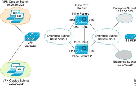
An Inline Posture high availability (HA) pair consists of two physical Inline Posture nodes configured as a cluster that have heartbeat links on the eth2 and eth3 interfaces, connected by dedicated cables. Each Inline Posture node has its own physical IP addresses on the trusted and untrusted Ethernet interfaces, but a separate service IP address must be assigned to the cluster as a whole.
Note
For example, the untrusted IP address for IPEP1 can be10.20.70.101, and the untrusted IP address for IPEP2 can be 10.20.70.102. However, the service IP address for both nodes on the untrusted side of the network would be10.20.70.100. The active Inline Posture node in the pair, at any point of time, assumes the service IP address on the untrusted side of the network. The same holds true for the trusted side of the network.
Figure 10-4 shows an example of an Inline Posture high availability router mode configuration. Note the dedicated cables that connect the eth2 and eth3 interfaces between the two nodes to facilitate the heartbeat communication that checks for failure in the active node.
Figure 10-4 Inline Posture Router Mode High Availability Example
Configuring Inline Posture High Availability in Bridged Mode
The following guidelines apply to an Inline Posture bridged mode high availability configuration:
•
•
Inline Posture Guidelines for Distributed Deployment
Before you begin configuring an Inline Posture node in a distributed deployment, be sure you understand the following statements:
1.
2.
3.
4.
5.
6.
Note
Deploying an Inline Posture Node
The initial process for configuring an Inline Posture node is the same, whether it is intended to be a standalone node or part of an active-standby pair. This section covers the series of tasks you must complete to configure an Inline Posture node on your Cisco ISE network.
To configure an Inline Posture node, complete the following tasks:
1.
2.
3.
4.
Configuring Inline Posture in Bridged or Router Mode
To introduce an Inline Posture node in your Cisco ISE network you must first register the Inline Posture node with the primary Policy Service ISE node, configure the Inline Posture settings, and then create authorization profiles and policies that establish the Inline Posture gatekeeping policies.
The Inline Posture node is a RADIUS proxy that interfaces with NADs as their RADIUS server, making the NADs (VPN gateway, WLC) RADIUS clients. As a proxy, Inline Posture interfaces with the Policy Service ISE node as a client, making the Policy Service ISE node its RADIUS server.
Prerequisites
•
•
Note
•
•
Warning
To configure Inline Posture in bridged or router mode, complete the following steps:
Step 1
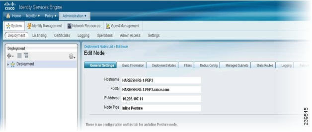
Step 2
Figure 10-5 Edit Inline Posture Node
The tabs change to General Settings, Basic Information, Deployment Modes, Filters, Radius Config, Managed Subnets, Static Routes, Logging, and Failover.
Note
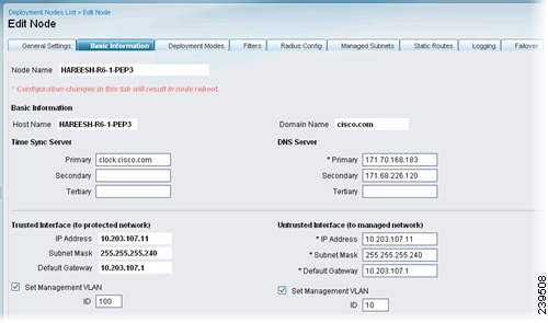
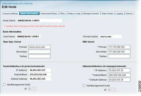
Step 3
•
•
•
•
Figure 10-6 is an example of a bridged mode configuration. Figure 10-7 is an example of a router mode configuration.
Figure 10-6 Basic Information (Bridged)
Figure 10-7 Basic Information (Router)
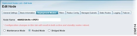
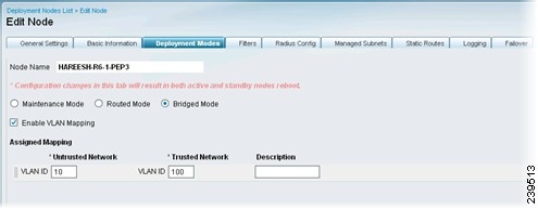
Step 4
•
•
For VLAN mapping, you should also do the following:
–
–
Figure 10-8 Deployment Modes (Router)
Figure 10-9 Deployment Modes (Bridged)
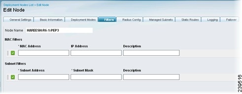
Step 5
You can use MAC and subnet filters to bypass Inline Posture enforcement to certain endpoints or devices on the untrusted side of the network. For example, if VPN or WLC management traffic is required to pass through Inline Posture, you would not want to subject those particular NADs to Cisco ISE policy enforcement. By providing the MAC address and IP address for these NADs on a filter, you can then access the user interface or configuration terminal by way of Inline Posture without restrictions.
•
•
Note
Figure 10-10 Filters
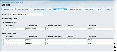
Step 6
•
•
•
Note
RADIUS configuration is mandatory. At least one client and one server configuration is necessary for Inline Posture. For more information on RADIUS proxy services, see Proxy Service, page 15-20.
Figure 10-11 RADIUS Configuration
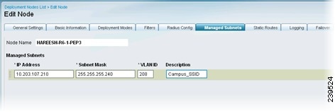
Step 7
•
•
•
•
For subnets of endpoints that are in Layer 2 proximity to the Inline Posture node (such as a WLC), you must configure managed subnets. This configuration requires an unused IP address in the same subnet as the managed subnet, along with the VLAN (if any) of the subnet. You can have multiple managed subnet entries.
Figure 10-12 Managed Subnets
Step 8
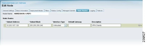
When the subnets of the endpoints under Cisco ISE control are Layer 3 away from the Inline Posture node, a static route entry is needed. For example, if a VPN gateway device (that sends managed subnet traffic to the Inline Posture untrusted interface) is two hops away, its client subnet needs to have a static route defined for Inline Posture. The network on the trusted side should know to send traffic to the Inline Posture trusted interface.
Figure 10-13 Static Routes
Step 9
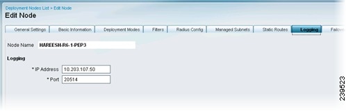
An IP address and port (default 20514) for logging Inline Posture events are mandatory. This requirement ensures that the viable status of the Inline Posture node is displayed on the Cisco ISE dashboard in the System Summary dashlet, and that other log information regarding the nodes is available.
Figure 10-14 Logging
Step 10
Next Steps
To complete the configuration setup of the Inline Posture node, complete the following tasks, creating three DACLs, authorization profiles, and authorization policy rules: unknown, compliant, and noncompliant.
1.
2.
Note
3.
Troubleshooting Topics
•
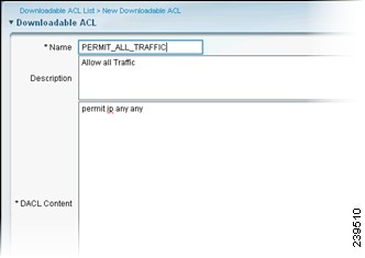
Creating Inline Posture Downloadable Access Control Lists
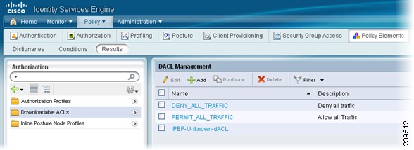
Downloadable access control lists (DACLs) are building blocks for authorization profiles, and they provide the rules for the profiles to follow. Access control lists (ACLs) prevent unwanted traffic from entering the network by filtering source and destination IP addresses, transport protocols, and other variables, using the RADIUS protocol.
After you create DACLs as named permission objects, add them to authorization profiles, which you then specify as the result of an authorization policy. For more information on DACLs, see Understanding Authorization Policies, page 16-1.
Figure 10-15 Inline Posture DACLs
Note
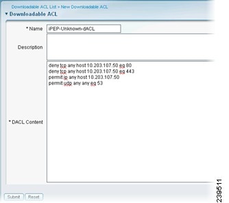
To create a DACL for Inline Posture, complete the following steps:
Step 1
•
•
•
Figure 10-16 Inline Posture DACL Compliance Unknown
Figure 10-17 Inline Posture DACL Compliant
Step 2
Troubleshooting Topics
•
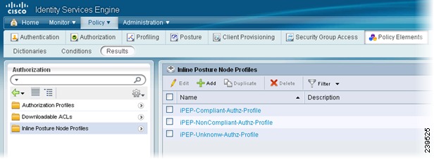
Creating Inline Posture Node Profiles
This section describes how to create authorization profiles for Inline Posture. You create three Inline Posture authorization profiles, as well an authorization profile for a NAD. For more information, see Cisco ISE Authorization Policies and Profiles, page 16-5.
All Inline Posture inbound profiles are automatically set to cisco-av-pair=ipep-authz=true so that the Inline Posture node is sure to apply these rules, instead of proxying them on to the NADs. The URL redirect is essential for client provisioning, as well as agent discovery redirection.
To create authorization profiles for NAD and Inline Posture, complete the following steps:
Step 1
Note
Step 2
Figure 10-18 Inline Posture Profiles
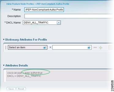
Specify the appropriate DACL for each of the following authorization profiles:
•
From the Inline Posture Authorization Profiles page, choose Cisco-AV-pair from the drop-down menu, enter the following URL redirect in the text field, and click Submit:
url-redirect=https://ip:8443/guestportal/gateway?sessionld=SessionValue&Action=cpp
The URL redirect appears in the Attributes Details field.
Figure 10-19 Unknown Authorization Profile
You are redirected to a web page where you download and install an agent. The agent then scans your system. If your system passes, you are automatically granted full access. If your system does not pass, you are denied access.
•
•
Figure 10-20 Noncompliant Authorization Profile
Step 3
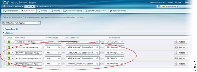
Creating an Inline Posture Authorization Policy
Authorization policies provide the means for controlling access to the network and its resources. Cisco ISE lets you define a number of different authorization policies.
The elements that define the authorization policy are referenced when you create policy rules. Your choice of conditions and attributes defines the authorization profile. Figure 10-21 shows the authorization rules that are necessary for VPN and WLC access.
Figure 10-21 Authorization Rules for VPN and WLC Access
For more information on authorization policies, see Cisco ISE Authorization Policies and Profiles, page 16-5.
To create authorization policies, complete the following steps:
Step 1
Step 2
•
•
•
Step 3
•
•
•
Step 4
•
•
•
Step 5
Next Step
Complete the following task: Adding Inline Posture as a RADIUS Client.
Configuring Inline Posture for High Availability
This section explains how to configure two Inline Posture nodes for high availability. One node is specified as the primary unit in the pair and becomes the active node by default. The other becomes the secondary node, which is a standby unit in case of default.
A high availability node failover prompts the standby node to take over the service IP address. After this process occurs, an administrator must correct the failed Inline Posture node and revert it to the earlier configuration, as needed. Since high availability failover is stateless, all active sessions are automatically reauthorized after a failover occurs.
This section covers the following topics:
•
•
Configuring a High Availability Pair
This section shows you how to define a high availability relationship between two registered Inline Posture nodes.
In the example that is presented, the service IP address used for the bridged mode high availability pair is different from the physical IP addresses of the Inline Posture nodes, effectively creating a cluster. The WLC interacts with the cluster as a single unit, using the service IP address. For this reason, the service IP is defined for the trusted and untrusted networks.
Configuring Primary and Secondary Inline Posture Nodes
Warning
Prerequisites
•
•
•
•
•
To configure an Inline Posture high availability pair, complete the following steps:
Step 1
Step 2
Step 3
Step 4
Step 5
Step 6
a.
b.
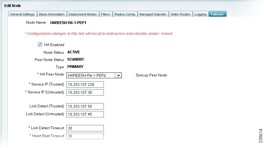
Then, Enter a Link-Detect Timeout value. The default value of 30 seconds is recommended. However, there is no maximum value.
Link-detect ensures that the Inline Posture node maintains communication with the Policy Service ISE node. If the active node does not receive notification (ping) from the Policy Service ISE node at the specified intervals, the active node fails over to the standby node.
Step 7
The heartbeat is a message that is sent between the two Inline Posture nodes at specified intervals. The heartbeat happens on eth2 and eth3 interfaces. If the heartbeat stops or does not receive a response in the allotted time, failover occurs.
Figure 10-22 Failover
Step 8
•
–
–
–
–
•
–
–
–
–
Step 9
Note
Step 10
When the nodes come back up, they are configured as primary and secondary, according to the settings you specified. You can view the state of a node by selecting the node to edit, as described in Step 2, and then clicking the Failover tab.
Note that the primary node has more options available for editing. That is because you make all configuration changes on the primary node. Configuration changes made to the primary node are automatically populated onto the secondary node. For this reason, the secondary node is read-only.
The following screenshots compare the Failover tabs of the active primary and standby secondary Inline Posture nodes.
Figure 10-23 Comparison of Active and Standby Options
Next Step
Complete the following task: Adding Inline Posture as a RADIUS Client.
Troubleshooting Topics
•
Syncing an Inline Posture Node
The procedure that is covered in this section assumes that you have already configured two Inline Posture nodes in an active-standby pair. The purpose of this section is to show you how to sync one node in an active-standby pair to the other node.
Prerequisites
•
•
•
To sync one Inline Posture node to another, complete the following steps:
Step 1
Step 2
Step 3
Step 4
Data from the selected node is automatically transferred to its peer node.
Troubleshooting Topics
•
Adding Inline Posture as a RADIUS Client
For a standalone Inline Posture node, you need to add the trusted IP address as a RADIUS client. For a high availability pair, add the service IP address for the trusted interface as a RADIUS client. This section covers the basic steps for this task. For more in-depth information, see Chapter 6, "Managing Network Devices."
Prerequisites
You must have completed the tasks in the appropriate section:
•
•
To add Inline Posture as a RADIUS client, complete the following steps:
Step 1
Step 2
Step 3
Step 4
•
•
Step 5
Step 6
Step 7
Step 8
Next Step
•
Monitoring an Inline Posture Node
You can monitor the health of a deployed Inline Posture node from the Cisco ISE dashboard, that is running on the Administration ISE node. The Inline Posture node appears on the System Summary dashlet. A green icon with a check mark means that the system is healthy. A yellow icon indicates a warning, and a red icon indicates of a critical system failure. Sparklines indicate the utilization of CPU, memory, and latency over time. You can choose to display data for the past 24 hours or the last 60 minutes.
When you hover the cursor over the health icon, a quick view dialog appears showing detailed information on system health.
Figure 10-24 System Summary Dashlet
For more information, see Cisco ISE Dashboard Monitoring, page 22-3.
Removing an Inline Posture Node from Deployment
To remove an Inline Posture node from the deployment, you must first change it to maintenance mode, and then you can deregister it. Maintenance mode is a neutral state that allows the node to smoothly transition to the network or from a deployment.
Prerequisites
•
To remove a node from deployment, complete the following steps:
Step 1
Step 2
Step 3
Step 4
Step 5
You are prompted with the following message: Are you sure you want to deregister the selected items?
Step 6
Troubleshooting Topics
•