Feedback
Table Of Contents
Connecting an Appliance to a Terminal Server
Understanding Time on the Sensor
Correcting the Time on the Sensor
10/100Base-TX and 10/100/1000Base-TX Connectors
Introducing the Sensor
This chapter introduces the sensor and provides information you should know before you install the sensor. In this guide, the term "sensor" refers to all models unless specifically noted otherwise. For a complete list of supported sensors and their model numbers, see Supported Sensors.
This chapter contains the following sections:
How the Sensor Functions
This section describes how the sensor functions, and contains the following topics:
Capturing Network Traffic
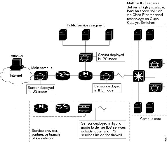
The sensor can operate in either promiscuous or inline mode. Figure 1-1 shows how you can deploy a combination of sensors operating in both inline (IPS) and promiscuous (IDS) modes to protect your network.
Figure 1-1 Comprehensive Deployment Solutions
Note
IDS-4210 and NM-CIDS do not operate in inline mode.
The command and control interface is always Ethernet. This interface has an assigned IP address, which allows it to communicate with the manager workstation or network devices (Cisco switches, routers, and firewalls). Because this interface is visible on the network, you should use encryption to maintain data privacy. SSH is used to protect the CLI and TLS/SSL is used to protect the manager workstation. Both SSH and TLS/SSL are enabled by default on the manager workstations.
When responding to attacks, the sensor can do the following:
•
Note
•
Note
•
IP session logs are used to gather information about unauthorized use. IP log files are written when a certain event or events occur that you have configured the appliance to look for.
•
Sensor Interfaces
The command and control interface is permanently mapped to a specific physical interface, which depends on the type of sensor you have. You can let the sensing interfaces operate in promiscuous mode, or you can pair the network sensing interfaces into logical interfaces called "inline pairs." You must enable the interfaces or inline pairs before the sensor can monitor traffic.
Note
The sensing interface does not have an IP address assigned to it and is therefore invisible to attackers. This lets the sensor monitor the data stream without letting attackers know they are being watched. Promiscuous mode is contrasted by inline technology where all packets entering or leaving the network must pass through the sensor. For more information, see Promiscuous Mode and Inline Mode.
The sensor monitors traffic on interfaces or inline pairs that are assigned to the default virtual sensor. For more information, refer to Assigning Interfaces to the Virtual Sensor.
To configure the sensor so that traffic continues to flow through inline pairs even when SensorApp is not running, you can enable bypass mode. Bypass mode minimizes dataflow interruptions during reconfiguration, service pack installation, or software failure.
The sensor detects the interfaces of modules that have been installed while the chassis was powered off. You can configure them the next time you start the sensor. If a module is removed, the sensor detects the absence of the interfaces the next time it is started. Your interface configuration is retained, but the sensor ignores it if the interfaces are not present.
The following interface configuration events are reported as status events:
•
•
•
•
Promiscuous Mode
In promiscuous mode, packets do not flow through the IPS. The sensor analyzes a copy of the monitored traffic rather than the actual forwarded packet. The advantage of operating in promiscuous mode is that the IPS does not affect the packet flow with the forwarded traffic. The disadvantage of operating in promiscuous mode, however, is the IPS cannot stop malicious traffic from reaching its intended target for certain types of attacks, such as atomic attacks (single-packet attacks). The response actions implemented by promiscuous IPS devices are post-event responses and often require assistance from other networking devices, for example, routers and firewalls, to respond to an attack. While such response actions can prevent some classes of attacks, for atomic attacks, however, the single packet has the chance of reaching the target system before the promiscuous-based sensor can apply an ACL modification on a managed device (such as a firewall, switch, or router).
Inline Mode
Operating in inline mode puts the IPS directly into the traffic flow and affects packet-forwarding rates making them slower by adding latency. An inline IPS sits in the fast-path, which allows the sensor to stop attacks by dropping malicious traffic before it reaches the intended target, thus providing a protective service. Not only is the inline device processing information on layers 3 and 4, but it is also analyzing the contents and payload of the packets for more sophisticated embedded attacks (layers 3 to 7). This deeper analysis lets the system identify and stop and/or block attacks that would normally pass through a traditional firewall device.
In inline mode, a packet comes in through the first interface of the pair on the sensor and out the second interface of the pair. The packet is sent to the second interface of the pair unless that packet is being denied or modified by a signature.
Note
TCP Reset
You need to designate an alternate TCP reset interface in the following situations:
•
•
Note
•
Note
Supported Interfaces
Table 1-1 describes the interface support for appliances and modules running Cisco IPS 5.0:
Table 1-1 Interface Support
InlineIDS-4210
—
None
N/A
All
IDS-4215
—
None
N/A
All
IDS-4215
4FE
FastEthernet0/1
4FE
FastEthernetS/01
FastEthernetS/1
FastEthernetS/2
FastEthernetS/31/0<->1/1
1/0<->1/2
1/0<->1/3
1/1<->1/2
1/1<->1/3
1/2<->1/3
0/1<->1/0
0/1<->1/1
0/1<->1/2
0/1<->1/3FastEthernet0/0
IDS-4235
—
None
N/A
All
IDS-4235
4FE
4FE
FastEthernetS/0
FastEthernetS/1
FastEthernetS/2
FastEthernetS/31/0<->1/1
1/0<->1/2
1/0<->1/3
1/1<->1/2
1/1<->1/3
1/2<->1/3GigabitEthernet0/0
GigabitEthernet0/1IDS-4250
—
None
N/A
All
IDS-4250
4FE
4FE
FastEthernetS/0
FastEthernetS/1
FastEthernetS/2
FastEthernetS/31/0<->1/1
1/0<->1/2
1/0<->1/3
1/1<->1/2
1/1<->1/3
1/2<->1/3GigabitEthernet0/0
GigabitEthernet0/1IDS-4250
SX
None
N/A
All
IDS-4250
XL
2 SX of the XL GigabitEthernet2/0
GigabitEthernet2/12/0<->2/1
GigabitEthernet0/0
GigabitEthernet0/1IDSM-2
—
port 7 and 8
GigabitEthernet0/7
GigabitEthernet0/80/7<->0/8
GigabitEthernet0/2
IPS-4240
—
4 onboard GE
GigabitEthernet0/0
GigabitEthernet0/1
GigabitEthernet0/2
GigabitEthernet0/30/0<->0/1
0/0<->0/2
0/0<->0/3
0/1<->0/2
0/1<->0/3
0/2<->0/3Management0/0
IPS-4255
—
4 onboard GE
GigabitEthernet0/0
GigabitEthernet0/1
GigabitEthernet0/2
GigabitEthernet0/30/0<->0/1
0/0<->0/2
0/0<->0/3
0/1<->0/2
0/1<->0/3
0/2<->0/3Management0/0
NM-CIDS
—
None
N/A
All
AIP-SSM-10
—
GigabitEthernet0/1
By security context
GigabitEthernet0/0
AIP-SSM-20
—
GigabitEthernet0/1
By security context
GigabitEthernet0/0
1 The 4FE card can be installed in either slot 1 or 2. S indicates the slot number, which can be either 1 or 2.
Your Network Topology
Before you deploy and configure your sensors, you should understand the following about your network:
•
•
•
This knowledge will help you determine how many sensors are required, the hardware configuration for each sensor (for example, the size and type of network interface cards), and how many managers are needed.
Supported Sensors
Table 1-2 lists the sensors (appliances and modules) that are supported by Cisco IPS 5.0.
Note
Caution
Table 1-2 Supported Sensors
IDS-4210
IDS-4210
IDS-4210-K9
IDS-4210-NFR—
—
—IDS-4215
IDS-4215-K9
IDS-4215-4FE-K91IDS-4FE-INT=
—IDS-4235
IDS-4235-K9
IDS-4FE-INT=
IDS-4250
IDS-4250-TX-K9
IDS-4250-SX-K9
IDS-4250-XL-K9IDS-4FE-INT=
IDS-4250-SX-INT=
IDS-XL-INT=
IDS-XL-INT=
—IPS-4240
IPS-4240-K9
—
IPS-4255
IPS-4255-K9
—
—
AIP-SSM-10
ASA-SSM-AIP-10-K9
—
AIP-SSM-20
ASA-SSM-AIP-20-K9
—
IDSM-2
WS-SVC-IDSM2-K9
—
NM-CIDS
NM-CIDS-K9
—
1 IDS-4215-4FE-K9 is the IDS-4215-K9 with the optional 4FE card (IDS-4FE-INT=) installed at the factory.
The following NRS and IDS appliance models are legacy models and are not supported in this document:
•
•
•
•
•
•
•
•
•
•
•
•
•
•
•
Note
Note
Appliances
This section describes the Cisco 4200 series appliance, and contains the following topics:
•
Introducing the Appliance
The appliance is a high-performance, plug-and-play device. The appliance is a component of the IPS, a network-based, real-time intrusion prevention system. For a list of supported appliances see Supported Sensors.
You can use the CLI, IDM, or ASDM to configure the appliance. For the list of IPS documents and how to access them, refer to Documentation Roadmap for Cisco Intrusion Prevention System 5.0.
You can configure the appliance to respond to recognized signatures as it captures and analyzes network traffic. These responses include logging the event, forwarding the event to the manager, performing a TCP reset, generating an IP log, capturing the alert trigger packet, and reconfiguring a router. The appliance offer significant protection to your network by helping to detect, classify, and stop threats including worms, spyware and adware, network viruses, and application abuse.
After being installed at key points in the network, the appliance monitors and performs real-time analysis of network traffic by looking for anomalies and misuse based on an extensive, embedded signature library. When the system detects unauthorized activity, appliances can terminate the specific connection, permanently block the attacking host, log the incident, and send an alert to the manager. Other legitimate connections continue to operate independently without interruption.
Appliances are optimized for specific data rates and are packaged in Ethernet, Fast Ethernet, and Gigabit Ethernet configurations. In switched environments, appliances must be connected SPAN port or VACL capture port of the switch.
The Cisco IPS 4200 series appliances provide the following:
•
•
•
•
Appliance Restrictions
The following restrictions apply to using and operating the appliance:
•
•
•
Connecting an Appliance to a Terminal Server
A terminal server is a router with multiple, low speed, asynchronous ports that are connected to other serial devices. You can use terminal servers to remotely manage network equipment, including appliances.
To set up a Cisco terminal server with RJ-45 or hydra cable assembly connections, follow these steps:
Step 1
•
–
–
•
–
–
Step 2
a.
config tline #logintransport input allstopbits 1flowcontrol hardwarespeed 9600exitexitwr memb.
Otherwise, for all other supported appliances, to direct all output to the terminal server, log in to the CLI and type the following commands:
sensor# configure terminalsensor(config)# display-serialOutput is directed to the serial port. Use the no display-serial command to redirect output to the keyboard and monitor.
Note
Note
Step 3
If a terminal session is not stopped properly, that is, if it does not receive an exit(0) signal from the application that initiated the session, the terminal session can remain open. When terminal sessions are not stopped properly, authentication is not performed on the next session that is opened on the serial port.
Caution
Caution
Modules
This section describes the modules, and contains the following topics:
Introducing AIP-SSM
The Cisco ASA Advanced Inspection and Prevention Security Services Module (AIP-SSM) is the IPS plug-in module in the Cisco ASA 5500 series adaptive security appliance (ASA). ASA software combines firewall, VPN concentrator, and intrusion detection and prevention software functionality into one software image.
There are two models of AIP-SSM: ASA-SSM-AIP-K9-10 and ASA-SSM-AIP-K9-20. ASA-SSM-AIP-K9-10 supports approximately 100 Mbps throughput and ASA-SSM-AIP-K9-20 supports approximately 200 Mbps. Only one module can populate the slot in ASA at a time.
AIP-SSM runs advanced IPS software that provides further security inspection either in inline mode or promiscuous mode. ASA diverts packets to the AIP-SSM just before the packet exits the egress interface (or before VPN encryption occurs, if configured) and after other firewall policies are applied. For example, packets that are blocked by an access list are not forwarded to AIP-SSM.
In promiscuous mode, the IPS receives packets over the GigabitEthernet interface, examines them for intrusive behavior, and generates alerts based on a positive result of the examination. In inline mode, there is the additional step of sending all packets, which did not result in an intrusion, back out the GigabitEthernet interface.
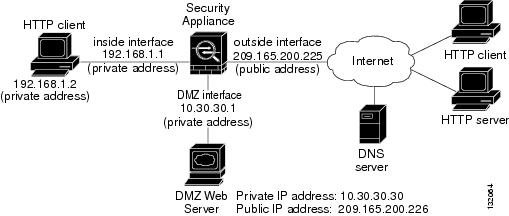
Figure 1-2 shows ASA with AIP-SSM in a typical DMZ configuration. A DMZ is a separate network located in the neutral zone between a private (inside) network and a public (outside) network. The web server is on the DMZ interface, and HTTP clients from both the inside and outside networks can access the web server securely.
In Figure 1-2 an HTTP client (10.10.10.10) on the inside network initiates HTTP communications with the DMZ web server (30.30.30.30). HTTP access to the DMZ web server is provided for all clients on the Internet; all other communications are denied. The network is configured to use an IP pool (a range of IP addresses available to the DMZ interface) of addresses between 30.30.30.50 and 30.30.30.60.
Figure 1-2 DMZ Configuration
For more information on setting up ASA, refer to the following URL:
http://www.cisco.com/en/US/products/ps6120/tsd_products_support_series_home.html
For more information on installing AIP-SSM, see Chapter 6 "Installing AIP-SSM." For more information on configuring AIP-SSM to receive IPS traffic, refer to Configuring AIP-SSM.
Introducing IDSM-2
The Cisco Catalyst 6500 Series Intrusion Detection System Services Module (IDSM-2) is a switching module that performs intrusion prevention in the Catalyst 6500 series switch and 7600 series router. You can use the CLI or IDSM to configure IDSM-2. You can configure IDSM-2 for promiscuous or inline mode.
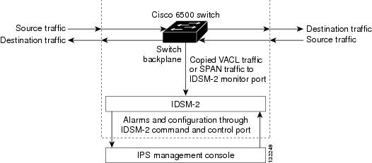
IDSM-2 performs network sensing—real-time monitoring of network packets through packet capture and analysis. IDSM-2 captures network packets and then reassembles and compares the packet data against attack signatures indicating typical intrusion activity. Network traffic is either copied to IDSM-2 based on security VACLs in the switch or is copied to IDSM-2 through the switch's SPAN port feature. These methods route user-specified traffic to IDSM-2 based on switch ports, VLANs, or traffic type to be inspected (see Figure 1-3).
Figure 1-3 IDSM-2 Block Diagram
IDSM-2 searches for patterns of misuse by examining either the data portion and/or the header portion of network packets. Content-based attacks contain potentially malicious data in the packet payload, whereas, context-based attacks contain potentially malicious data in the packet headers.
You can configure IDSM-2 to generate an alert when it detects potential attacks. Additionally, you can configure IDSM-2 to transmit TCP resets on the source VLAN, generate an IP log, and/or initiate blocking countermeasures on a firewall or other managed device. Alerts are generated by IDSM-2 through the Catalyst 6500 series switch backplane to the IPS manager, where they are logged or displayed on a graphical user interface.
Introducing NM-CIDS
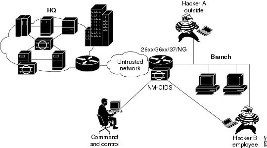
The Cisco Intrusion Detection System Network Module (NM-CIDS) integrates the Cisco IDS functionality into a branch office router. With NM-CIDS, you can implement full-featured IDS at your remote branch offices. You can install NM-CIDS in any one of the network module slots on the Cisco 2600, 3600, and 3700 series routers. NM-CIDS can monitor up to 45 Mbps of network traffic. See Software and Hardware Requirements for a list of supported routers. Only one NM-CIDS is supported per router. Figure 1-4 shows the router in a branch office environment.
Note
Figure 1-4 NM-CIDS in the Branch Office Router
NM-CIDS has one internal 10/100 Ethernet port that connects to the router's backplane. There is also one external 10/100-based Ethernet port that is used for device management (management of other routers and/or PIX Firewalls to perform blocking) and command and control of NM-CIDS by IDS managers.
NM-CIDS communicates with the router to exchange control and state information for bringing up and shutting down NM-CIDS and to exchange version and status information. NM-CIDS processes packets that are forwarded from selected interfaces on the router to the IDS interface on NM-CIDS. NM-CIDS analyzes the captured packets and compares them against a rule set of typical intrusion activity called signatures. If the captured packets match a defined intrusion pattern in the signatures, NM-CIDS can take one of two actions: it can make ACL changes on the router to block the attack, or it can send a TCP reset packet to the sender to stop the TCP session that is causing the attack.
In addition to analyzing captured packets to identify malicious activity, NM-CIDS can also perform IP session logging that can be configured as a response action on a per-signature basis. When the signature fires, session logs are created over a specified time period in a tcpdump format. You can view these logs using Ethereal or replay the IP session using tools such as TCP Replay.
You can manage and retrieve events from NM-CIDS through the CLI or IDM.
The IDS requires a reliable time source. All the events (alerts) must have the correct time stamp, otherwise, you cannot correctly analyze the logs after an attack. You cannot manually set the time on NM-CIDS. NM-CIDS gets its time from the Cisco router in which it is installed. Routers do not have a battery so they cannot preserve a time setting when they are powered off. You must set the router's clock each time you power up or reset the router, or you can configure the router to use NTP time synchronization. We recommend NTP time synchronization. You can configure either NM-CIDS itself or the router it is installed in to use NTP time synchronization. For more information, see Time Sources and the Sensor.
Time Sources and the Sensor
This section explains the importance of having a reliable time source for the sensors and how to correct the time if there is an error. It contains the following topics:
•
•
Understanding Time on the Sensor
The sensor requires a reliable time source. All events (alerts) must have the correct UTC and local time stamp, otherwise, you cannot correctly analyze the logs after an attack. When you initialize the sensor, you set up the time zones and summertime settings. for more information, see Initializing the Sensor.
Here is a summary of ways to set the time on sensors:
•
–
For the procedure, refer to Manually Setting the Clock.
–
You can configure the appliance to get its time from an NTP time synchronization source. For the procedure, refer to Configuring a Cisco Router to be an NTP Server. You will need the NTP server IP address, the NTP key ID, and the NTP key value. You can set up NTP on the appliance during initialization or you can configure NTP through the CLI, IDM, or ASDM.
Note
•
–
Note
Caution
–
You can configure IDSM-2 to get its time from an NTP time synchronization source. For the procedure, refer to Configuring a Cisco Router to be an NTP Server. You will need the NTP server IP address, the NTP key ID, and the NTP key value. You can configure IDSM-2 to use NTP during initialization or you can set up NTP through the CLI, IDM, or ASDM.
Note
•
–
Note
Caution
–
You can configure NM-CIDS to get its time from an NTP time synchronization source, such as a Cisco router other than the parent router. For the procedure, refer to Configuring a Cisco Router to be an NTP Server. You will need the NTP server IP address, the NTP key ID, and the NTP key value. You can configure NM-CIDS to use NTP during initialization or you can set up NTP through the CLI, IDM, or ASDM.
Note
•
–
Note
Caution
–
You can configure AIP-SSM to get its time from an NTP time synchronization source, such as a Cisco router other than the parent router. For the procedure, refer to Configuring a Cisco Router to be an NTP Server. You will need the NTP server IP address, the NTP key ID, and the NTP key value. You can configure AIP-SSM to use NTP during initialization or you can set up NTP through the CLI, IDM, or ASDM.
Note
Correcting the Time on the Sensor
If you set the time incorrectly, your stored events will have the incorrect time because they are stamped with the time the event was created.
The Event Store time stamp is always based on UTC time. If during the original sensor setup, you set the time incorrectly by specifying 8:00 p.m. rather than 8:00 a.m., when you do correct the error, the corrected time will be set backwards. New events might have times older than old events.
For example, if during the initial setup, you configure the sensor as central time with daylight saving time enabled and the local time is 8:04 p.m., the time is displayed as 20:04:37 CDT and has an offset from UTC of -5 hours (01:04:37 UTC, the next day). A week later at 9:00 a.m., you discover the error: the clock shows 21:00:23 CDT. You then change the time to 9:00 a.m. and now the clock shows 09:01:33 CDT. Because the offset from UTC has not changed, it requires that the UTC time now be 14:01:33 UTC, which creates the time stamp problem.
To ensure the integrity of the time stamp on the event records, you must clear the event archive of the older events by using the clear events command. For more information on the clear events command, refer to Clearing Events from the Event Store.
Caution
Installation Preparation
To prepare for installing sensors, follow these steps:
Step 1
Step 2
Step 3
Step 4
Step 5
For more information, see Site and Safety Guidelines.
Step 6
Step 7
Site and Safety Guidelines
This section describes site guidelines and safety precautions to take when working with electricity, with power supplies, and in an ESD environment. It contains the following topics:
•
•
Site Guidelines
Place the appliance on a desktop or mount it in a rack. The location of the appliance and the layout of the equipment rack or wiring room are extremely important for proper system operation. Equipment placed too close together, inadequate ventilation, and inaccessible panels can cause system malfunctions and shutdowns, and can make appliance maintenance difficult.
When planning the site layout and equipment locations, keep in mind the following precautions to help avoid equipment failures and reduce the possibility of environmentally-caused shutdowns. If you are experiencing shutdowns or unusually high errors with your existing equipment, these precautions may help you isolate the cause of failures and prevent future problems.
•
•
•
Rack Configuration Guidelines
Follow these guidelines to plan your equipment rack configuration:
•
•
•
•
Electrical Safety Guidelines
WarningFollow these guidelines when working on equipment powered by electricity:
•
•
•
•
•
–
–
–
–
•
•
•
Power Supply Guidelines
Follow these guidelines for power supplies:
•
•
•
–
–
–
–
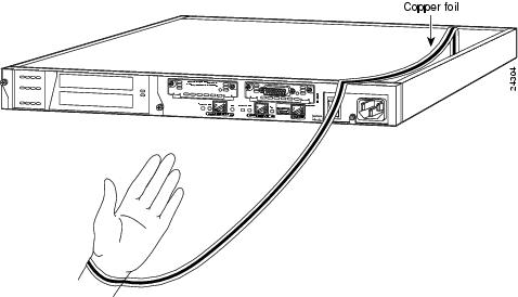
Working in an ESD Environment
Work on ESD-sensitive parts only at an approved static-safe station on a grounded static dissipative work surface, for example, an ESD workbench or static dissipative mat.
To remove and replace components in a sensor, follow these steps:
Step 1
Step 2
Note
Step 3
Step 4
Caution
Note
Cable Pinouts
This section describes pinout information for 10/100/1000BaseT, console, and RJ 45 to DB 9 ports, and the MGMT 10/100 Ethernet port. This section contains the following topics:
•
10/100Base-TX and 10/100/1000Base-TX Connectors
Sensors support 10/100/1000Base-TX ports. You must use at least a Category 5 cable for 100/1000Base-TX operations. You can use a Category 3 cable for 10Base-TX operations.
Note
The 10/100/1000Base-TX ports use standard RJ-45 connectors and support MDI and MDI-X connectors. Ethernet ports normally use MDI connectors and Ethernet ports on a hub normally use MDI-X connectors.
An Ethernet straight-through cable is used to connect an MDI to an MDI-X port. A cross-over cable is used to connect an MDI to an MDI port, or an MDI-X to an MDI-X port.
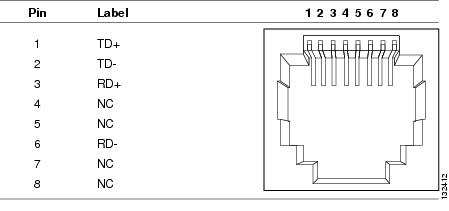
Figure 1-5 shows the 10/100Base-TX (RJ-45) port pinouts.
Figure 1-5 10/100 Port Pinouts
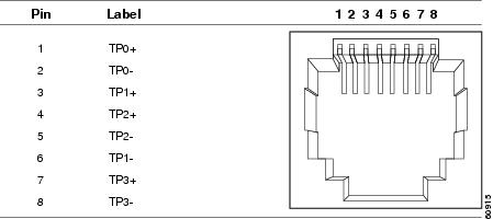
Figure 1-6 shows the 10/100/1000BASE-TX (RJ-45) port pinouts.
Figure 1-6 10/100/1000 Port Pinouts
Console Port (RJ-45)
Cisco products use the following types of RJ-45 cables:
•
•
•
Note
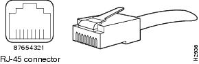
Figure 1-7 shows the RJ 45 cable.
Figure 1-7 RJ-45 Cable
To identify the RJ-45 cable type, hold the two ends of the cable next to each other so that you can see the colored wires inside the ends, as shown in Figure 1-8.
Figure 1-8 RJ-45 Cable Identification
Examine the sequence of colored wires to determine the type of RJ-45 cable, as follows:
•
•
•
RJ-45 to DB-9 or DB-25
Table 1-3 lists the cable pinouts for RJ-45 to DB-9 or DB-25.
Table 1-3 Cable Pinouts for RJ-45 to DB-9 or DB-25
RTS
8
8
DTR
7
6
TxD
6
2
GND
5
5
GND
4
5
RxD
3
3
DSR
2
4
CTS
1
7