Feedback
Table Of Contents
Front and Back Panel Features and Indicators
Installing and Removing the Bezel
Installing Center Mount Brackets
Installing Front Mount Brackets
Installing IDS-4210
This chapter describes IDS-4210 and how to install it and its accessories.
Note
IDS-4215 replaced IDS-4210, which is no longer sold.
Note
Note
This chapter contains the following sections:
•
Front and Back Panel Features and Indicators
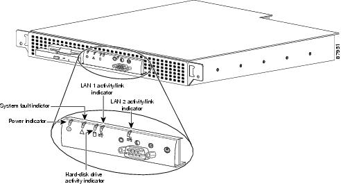
Figure 2-1shows the front panel indicators on IDS-4210.
Figure 2-1 Front Panel Features
Table 2-1 describes the appearance and function of the front panel indicators.
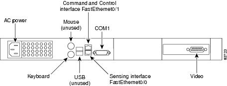
Figure 2-2 shows the back panel features on IDS-4210.
Figure 2-2 Back Panel Features
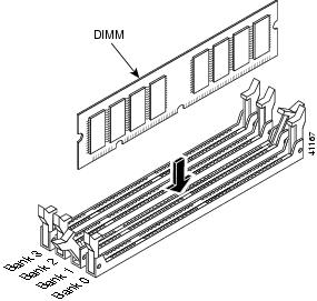
Upgrading the Memory
IDS-4210, IDS-4210-K9, and IDS-4210-NFR must have 512 MB of RAM to support Cisco IPS 5.0. If you are upgrading an existing IDS-4210, IDS-4210-K9, or IDS-4210-NFR to 5.0, you must insert one additional 256-MB DIMM (part number IDS-4210-MEM-U) to upgrade the memory to the required 512 MB minimum.
Note
Caution
To upgrade the memory, follow these steps:
Step 1
Step 2
sensor# reset powerdownWait for the power down message before continuing with Step 3.
Note
Step 3
Step 4
Step 5
For more information, see Working in an ESD Environment.
Step 6
Step 7
Note
Step 8
Step 9
Note
Step 10
Step 11
Note
Installing IDS-4210
Warning
Caution
Note
To install IDS-4210 on the network, follow these steps:
Step 1
Step 2
Note
Step 3
Table 2-2 Terminal Settings
Bits per second
9600
Data bits
8
Parity
None
Stop bits
1
Flow control
Hardware or RTS/CTS
Caution
Note
Step 4
IDS-4210 has the following interfaces:
•
•
Step 5
For the procedure, see Upgrading the Memory.
Caution
Step 6
Step 7
For the procedure, see Initializing the Sensor.
Step 8
For the procedure, see Obtaining Cisco IPS Software.
You are now ready to configure intrusion detection on the appliance.
For More Information
•
•
–
–
Installing the Accessories
You can install a bezel, and center or front mounting brackets for the IDS-4210. This section describes how to install the bezel and mounting brackets, contains the following topics:
•
•
•
Accessories Package Contents
The following items are shipped in the accessories package for IDS-4210:
•
•
•
•
•
•
•
–
–
–
Installing and Removing the Bezel
You can install a Cisco bezel for IDS-4210.
To install and remove the bezel on IDS-4210, follow these steps:
Step 1
a.
b.
c.
Step 2
Installing Center Mount Brackets
You need the following tools and supplies to install the brackets in a two-post, open-frame relay rack:
•
•
To install the center mount brackets in a two-post, open-frame relay rack, follow these steps:
Step 1
Step 2
Step 3
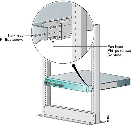
Figure 2-3 Installing Center Mount Brackets
Step 4
Step 5
Step 6
Step 7
Installing Front Mount Brackets
Make sure you have the following supplies (found in the front mount bracket assembly kit) and tools to install the front mount brackets in a two-post, open-frame relay rack:
•
•
•
•
Note
Figure 2-4 Front Mount Brackets
Caution
To install the front mount brackets, follow these steps:
Step 1
Step 2
Step 3
Step 4
Step 5
Note