Feedback
Table Of Contents
Software and Hardware Requirements
Installation and Removal Instructions
Installing NM-CIDS Using OIR Support
Removing NM-CIDS Using OIR Support
Installing NM-CIDS
This chapter lists the software and hardware requirements of NM-CIDS, and describes how to install and remove it.
Note
In Cisco IOS documentation, NM-CIDS is referred to as the Cisco IDS network module.
Note
This chapter contains the following sections:
•
•
Specifications
Table 8-1 lists the specifications for NM-CIDS.
Software and Hardware Requirements
NM-CIDS has the following software and hardware requirements.
NM-CIDS supports the following software:
•
•
•
Caution
NM-CIDS supports the following feature sets:
•
•
•
•
•
•
•
•
•
Table 8-2 lists supported and unsupported platforms for NM-CIDS.
Note
Table 8-3 lists the hardware specifications for NM-CIDS.
Table 8-3 Hardware Requirements
Processor
500 Mhz Intel Mobile Pentium III
Default SDRAM
512 MB
Maximum DSRAM
512 MB
Internal disk storage
NM-CIDS 20-GB IDE
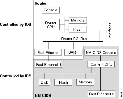
Hardware Architecture
NM-CIDS has the following hardware architecture:
•
•
•
•
•
Figure 8-1 shows the hardware architecture of NM-CIDS.
Figure 8-1 NM-CIDS Hardware Architecture
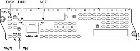
Front Panel Features
Figure 8-2 shows the front panel features of the NM-CIDS.
Figure 8-2 Front Panel Features
Table 8-4 describes the NM-CIDS states as indicated by the status indicators.
Interfaces
The router-side fast ethernet interface is known as "interface IDS-Sensor." This interface name appears in the show interface and show controller commands. You must assign the IP address to the interface to get console access to IDS.
Caution
For the procedure for assigning the IP address to gain access to the console and for setting up a loopback address, refer to Configuring Cisco IDS Interfaces on the Router.
Installation and Removal Instructions
You must install NM-CIDS offline in Cisco 2650XM, 2651XM, and 2961 series routers.
Caution
Cisco 3660 and Cisco 3700 series routers lets you replace network modules without switching off the router or affecting the operation of other interfaces. OIR provides uninterrupted operation to network users, maintains routing information, and ensures session preservation.
Note
Caution
This section contains the following topics:
Required Tools
You need the following tools and equipment to install NM-CIDS in a Cisco modular router chassis slot:
•
•
•
Installing NM-CIDS
This section describes how to install NM-CIDS off line and using OIR support, and contains the following topics:
•
Installing NM-CIDS Offline
You can install NM-CIDS in the chassis either before or after mounting the router, whichever is more convenient.
Caution
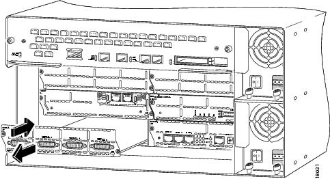
To install NM-CIDS, follow these steps:
Step 1
To channel ESD voltages to ground, do not unplug the power cable.
Step 2
Step 3
Save the blank panel for future use.
Step 4
Step 5
Step 6
Step 7
The following warning applies to routers that use a DC power supply:
WarningStep 8
Step 9
Step 10
For the procedure, see Initializing the Sensor.
Step 11
For the procedure, see Obtaining Cisco IPS Software.
You are now ready to configure intrusion detection on NM-CIDS.
For More Information
•
•
–
–
Installing NM-CIDS Using OIR Support
To install NM-CIDS using OIR support, follow these steps:
Step 1
Step 2
Step 3
Step 4
Step 5
Step 6
For the procedure, see Initializing the Sensor.
Step 7
For the procedure, see Obtaining Cisco IPS Software.
You are now ready to configure intrusion detection on NM-CIDS.
For More Information
•
•
–
–
Removing NM-CIDS
This section describes how to remove NM-CIDS offline or using OIR support, and contains the following topics:
•
Removing NM-CIDS Offline
You must turn off all power to the router before removing NM-CIDS.
To remove NM-CIDS from the router chassis, follow these steps:
Step 1
router# service-module IDS-Sensor slot_number/0 shutdownTrying 10.10.10.1, 2129 ... OpenWait for the shutdown message before continuing with Step 2:
%SERVICEMODULE-5-SHUTDOWN2:Service module IDS-Sensor1/0 shutdown completeStep 2
To channel ESD voltages to ground, do not unplug the power cable.
Step 3
Step 4
Step 5
Note
Removing NM-CIDS Using OIR Support
Caution
To remove NM-CIDS with OIR support, follow these steps:
Step 1
router# service-module IDS-Sensor slot_number/0 shutdownTrying 10.10.10.1, 2129 ... OpenWait for the shutdown message before continuing with Step 2:
%SERVICEMODULE-5-SHUTDOWN2:Service module IDS-Sensor1/0 shutdown completeStep 2
Step 3
Step 4
Note
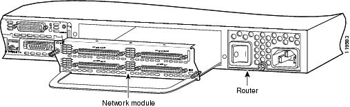
Blank Network Module Panels
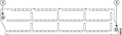
If the router is not fully configured with network modules, make sure that blank panels fill the unoccupied chassis slots to provide proper airflow as shown in Figure 8-3.
Figure 8-3 Blank Network Module Panel