-
Cisco Guard Configuration Guide (Software Version 6.0)
-
Index
-
Preface
-
Product Overview
-
Initializing the Guard
-
Configuring the Guard
-
Configuring Traffic Diversion
-
Configuring Zones
-
Configuring Zone Filters
-
Configuring Policy Templates and Policies
-
Learning the Zone Traffic Characteristics
-
Protecting Zones
-
Using Interactive Protect Mode
-
Using Attack Reports
-
Using Guard Diagnostics Tools
-
Performing Maintenance Tasks
-
Analyzing Guard Mitigation
-
Understanding Zone Traffic Diversion
-
Troubleshooting Diversion
-
 Feedback
Table Of Contents
Understanding the BGP Diversion Method
Guard BGP Configuration Example
Displaying the Guard Router Configuration File
Cisco Router BGP Configuration
Cisco Router BGP Configuration Example
Understanding Traffic Forwarding Methods
Policy-Based Routing Destination Forwarding Method
PBR Destination Configuration Guidelines
Guard PBR Destination Configuration
Cisco Router PBR Destination Configuration Examples
VPN Routing Forwarding Destination Forwarding Method
VRF-DST Configuration Guidelines
Policy-Based Routing VLAN Forwarding Method
Cisco Router PBR-VLAN Configuration
VPN Routing Forwarding VLAN Forwarding Method
Cisco Router VRF-VLAN Configuration
Tunnel Diversion Forwarding Method
Guard Tunnel Diversion Configuration
Cisco Router Tunnel Diversion Configuration
Guard Long Diversion Configuration
Cisco Router Long Diversion Configuration
Configuring Traffic Diversion
This chapter describes how to configure traffic diversion with the Cisco Guard (Guard).
Traffic diversion configuration is topology independent. The configuration procedures for Layer 2 and Layer 3 topologies are identical.
To save all configuration changes to the Guard memory, use the write memory command in router configuration mode.
Note
Information provided in this document regarding Cisco router configuration is for informational purposes only. Refer to the appropriate user guides for detailed information.
This chapter contains the following sections:
•
•
Understanding the BGP Diversion Method
Following standard Border Gateway Protocol (BGP) routing definitions, routers select the routing path with the longest matching prefix (also known as the "most specific"). After establishing a BGP session with the router, the Guard sends a routing update where the Guard is listed as the best path for the protected zone. The network prefix that the Guard announces is longer than the one already listed in the router's routing table, overriding the router's routing table definition. The prefix subnet is configured per zone subnet IP address. BGP is configured similarly in all networks.
To configure traffic diversion in Layer 2 and Layer 3 network topologies, perform the following:
1.
2.
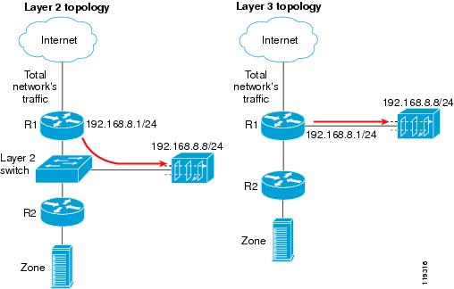
Figure 4-1 provides examples of Layer 2 and Layer 3 network topologies. In both network topologies, the Guard diverts the traffic from router R1.
Figure 4-1 BGP Configuration
After BGP diversion is established, the router's routing tables points to the Guard as the best route to the zone and the router forwards all traffic destined to the zone's IP address to the Guard.
This section contains the following topics:
•
BGP Configuration Guidelines
This section provides general guidelines for BGP configuration on the Guard and on a divert-from router.
Note
Note
Follow these guidelines when the Guard and adjacent routers operate using common eBGP:
1.
The Guard sends routing information only when it diverts traffic. This route appear in the router's routing tables. Using a recognizable value allows you to easily identify the Guard in the router's routing tables.
2.
•
•
A match in the community attributes enables the Guard to filter BGP announcements on the router and enforce this policy.
3.
See the "BGP Diverting Method" section on page A-5 for more information about BGP.
Guard BGP Configuration
You can configure BGP on the Guard using the Zebra application (see http://www.zebra.org for more information about the Zebra application).
Note
To enter diversion configuration on the Guard, perform the following steps:
Step 1
admin@GUARD-conf# routerThe following prompt appears, indicating that the system has entered the Zebra application in nonprivileged mode:
router>
Tip
Step 2
router> enableThe following prompt appears, indicating that the system has entered the Zebra application privileged mode:
router#
Note
Step 3
router# config terminalThe following prompt appears, indicating that the system has entered the Zebra application configuration mode:
router(config)#Step 4
•
•
•
Note
The following commands must be entered on the Guard:
router(config)# router bgp <Guard-AS-number>router(config-router)# bgp router-id <Guard-IP-address>router(config-router)# redistribute guardrouter(config-router)# neighbor <Router-IP-address> remote-as <Router-AS-number>router(config-router)# neighbor <Router-IP-address> description <description>router(config-router)# neighbor <Router-IP-address> soft-reconfiguration inboundrouter(config-router)# neighbor <Router-IP-address> distribute-list nothing-in inrouter(config-router)# neighbor <Router-IP-address> route-map Guard-out outrouter(config-router)# exitrouter(config)# access-list nothing-in deny anyrouter(config)# route-map Guard-out permit 10router(config-route-map)# set community no-export no-advertiseThis section contains the following topics:
•
•
Guard BGP Configuration Example
To display the Guard router configuration, enter the show running-config command from the router command level. In the following example, the router's AS number is 100, and the Guard's AS number is 64555.
The following partial sample output is displayed:
router# show running-config... ... ...router bgp 64555bgp router-id 192.168.8.8redistribute guardneighbor 192.168.8.1 remote-as 100neighbor 192.168.8.1 description divert-from routerneighbor 192.168.8.1 soft-reconfiguration inboundneighbor 192.168.8.1 distribute-list nothing-in inneighbor 192.168.8.1 route-map Guard-out out!access-list nothing-in deny any!route-map Guard-out permit 10set community 100:64555 no-export no-advertise... ... ...Displaying the Guard Router Configuration File
You can display the Guard router configuration file by entering the following command from the Global command group level:
show running-config routerThe information that displays is the same information that displays when you enter the show running-config command from the router command level (see the "Guard BGP Configuration Example" section.
Cisco Router BGP Configuration
This section describes the router BGP configuration used when you configure a traffic diversion. The syntax in the commands is taken from the BGP configuration on a Cisco router.
These commands observe the following conventions:
•
•
•
The following configuration example shows the commands to use to configure BGP on a Cisco router:
R7200(config)# router bgp <Router-AS>R7200(config-router)# bgp log-neighbor-changesR7200(config-router)# neighbor <Guard-IP-address> remote-as GuardASR7200(config-router)# neighbor <Guard-IP-address> description <description>R7200(config-router)# neighbor <Guard-IP-address> soft-reconfiguration inboundR7200(config-router)# neighbor <Guard-IP-address> distribute-list routesToGuard outR7200(config-router)# neighbor <Guard-IP-address> route-map Guard-in inR7200(config-router)# no synchronizationR7200(config-router)# exitR7200(config)# ip bgp-community new-formatR7200(config)# ip community-list expanded <Guard-community-name> permit no-export no-advertiseR7200(config)# route-map Guard-in permit 10R7200(config-route-map)# match community <Guard-community-name> exact matchR7200(config-route-map)# exitR7200(config)# ip access-list standard routestoGuardR7200(config-std-nacl)# deny anyThe no synchronization command prevents the distribution of the Guard BGP routing updates into Interior Gateway Protocol (IGP).
Cisco Router BGP Configuration Example
To display the router configuration, enter the show running-config command from the router global command level. In the following example, the router's AS number is 100, and the Guard's AS number is 64555.
The following partial sample output is displayed:
R7200# show running-config... ... ...router bgp 100bgp log-neighbor-changesneighbor 192.168.8.8 remote-as 64555neighbor 192.168.8.8 description Guardneighbor 192.168.8.8 soft-reconfiguration inboundneighbor 192.168.8.8 distribute-list routesToGuard outneighbor 192.168.8.8 route-map Guard-in inno synchronization!ip bgp-community new-formatip community-list expanded Guard permit 100:64555 no-export no- advertise!route-map Guard-in permit 10match community Guard exact matchip access-list standard routesToGuarddeny any... ... ...Understanding Traffic Forwarding Methods
This section provides details on traffic forwarding methods. Traffic forwarding methods are used to forward the cleaned traffic from the Guard to the next-hop router. See the "Understanding the Traffic Forwarding Methods" section on page A-6 for more information.
The following terminology is used in this section:
•
•
•
This section contains the following topics:
•
•
•
•
•
Layer-2 Forwarding Method
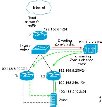
The Layer-2 Forwarding (L2F) method is used in a Layer 2 topology when all three devices—the Cisco Guard, the divert-from router, and the next-hop router—are located in one shared IP network (Figure 4-2).
In a Layer 2 topology, a divert-from router and an inject-to router are two separate devices. The next-hop router and the inject-to router are the same device.
The Guard issues an ARP query to resolve the MAC address of the inject-to/next-hop router and then forwards the traffic. For this reason, no configuration on the routers is required when using the L2F method.
The zone may be connected as follows:
•
•
Figure 4-2 Layer-2 Forwarding Method
This section contains the following topics:
Guard L2F Configuration
This section describes the Guard L2F configurations and contains the following topics:
Interface Statements
You can configure the Guard's out-of-band interface as described in the "Configuring a Physical Interface" section.
The following example shows how to configure out-of-band interface giga1:
admin@GUARD-conf# interface giga1admin@GUARD-conf-if-giga1# ip address 192.168.8.8 255.255.255.0BGP Statements
You can enter the Guard router BGP configuration as described in the "Guard BGP Configuration" section.
In the following example, the Guard's AS is 64555. The router's AS is 100 and the IP address is 192.168.8.1:
router bgp 64555redistribute guardneighbor 192.168.8.1 remote-as 100neighbor 192.168.8.1 description C7513neighbor 192.168.8.1 distribute-list nothing-in inneighbor 192.168.8.1 soft-reconfiguration inboundneighbor 192.168.8.1 route-map filt-out out!route-map filt-out permit 10set community no-advertise no-export 100:64555!access-list nothing-in deny anyInjection Configuration
You can configure traffic injection from the Guard to the zone by adding a static route to the zone or the next-hop router according to the network topology. You should configure the static route at the Guard's router configuration level.
The following example shows how to configure a static route for the zone's network (192.168.240.0/24) through the next-hop router (192.168.8.250):
router# configure terminalrouter(config)# ip route 192.168.240.0 255.255.255.0 192.168.8.250Router L2F Configuration
No configuration is required on the router.
Policy-Based Routing Destination Forwarding Method
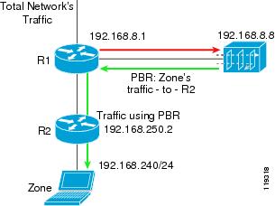
Policy-Based Routing (PBR) destination is a static forwarding method that is deployed in Layer 3 network topologies, where the Guard forwards the filtered traffic to the same router from which the traffic was diverted (Figure 4-3).
Figure 4-3 PBR Destination Forwarding Method
To enable the Guard to divert the zone's traffic from the router, the Guard modifies the zone's route in the router's routing table and the Guard is listed as the best path to the zone.
An endless routing loop could occur if the router's routing table is not changed. Because the only entry for the traffic destined to the zone in the router's routing table is the Guard, filtered traffic from the Guard is sent back to the Guard.
To overcome routing loops, you can configure PBR destination on the inject-to router. PBR destination allows you to create rules that override the rules in the router's routing table and avoid endless routing loops. PBR destination enables you to add rules that are applied to the filtered traffic. These rules instruct the router to forward the filtered traffic to the zone, regardless of the routing table entries.
To configure the diversion in this network topology, you can configure the traffic diversion process using BGP (see the "Guard BGP Configuration" section for more information).
This section contains the following topics:
•
•
•
PBR Destination Configuration Guidelines
The guidelines provided in this section apply to PBR destination configurations on any inject-to router.
To configure PBR destination on an inject-to router, follow these guidelines:
1.
Note
2.
•
•
PBR destination is applied using the route-map command and the match and set commands to define the conditions for policy routing packets. To enable PBR, you must create a route map that specifies the match criteria and the resulting action if all of the match clauses are met. The user must enable PBR destination for the configured route map on a particular interface. All packets arriving on the specified interface that match the match clause are subject to PBR destination.
A PBR destination configuration consists the following three parts:
•
You can define a separate route-map entry and sequence number for traffic that is to be forwarded to the zone and for all other traffic.
The sequence is configured using the route-map command. Using the route-map command puts the router into route-map configuration mode.
•
•
Guard PBR Destination Configuration
The configuration in the following example refers to the network in Figure 4-3.
•
•
The following example shows how to configure a static route for the zone's network (192.168.240.0/24):
router# configure terminalrouter(config)# ip route 192.168.240.0 255.255.255.0 192.168.8.1Cisco Router PBR Destination Configuration Examples
The following example shows the router PBR destination configuration used when configuring a diversion.
R7200(config)# interface FastEthernet 0/2R7200(config-if)# description <Interface connected to the Guard>R7200(config-if)# ip address <Router interface IP address> <Router interface IP mask>R7200(config-if)# no ip directed-broadcastR7200(config-if)# ip policy route-map <Guard-PBR-name>R7200(config-if)# exitR7200(config)# ip access-list extended <Zone-name>R7200(config-ext-nacl)# permit ip any host <Zone IP address>R7200(config-ext-nacl)# exitR7200(config)# route-map <Guard-PBR-name> permit 10R7200(config-route-map)# match ip address <Zone-name>R7200(config-route-map)# set ip next-hop <next-hop router IP address>R7200(config-route-map)# exitR7200(config)# route-map < Guard-PBR-name > permit 100R7200(config-route-map)# description let thru all other packets without modifying next-hopThis example shows a PBR destination traffic forwarding configuration for the sample network in Figure 4-3. To display the router configuration, you enter the show running-config command.
The following partial example screen is displayed:
R7200# show running-config... ... ...interface FastEthernet0/2description Interface connected to the Guardip address 192.168.8.1 255.255.255.0no ip directed-broadcastip policy route-map GuardPbr!ip access-list extended zone-Apermit ip any host 192.168.240.2!route-map GuardPbr permit 10match ip address zone-Aset ip next-hop 192.168.250.2!route-map GuardPbr permit 100description let thru all other packets without modifying next-hopVPN Routing Forwarding Destination Forwarding Method
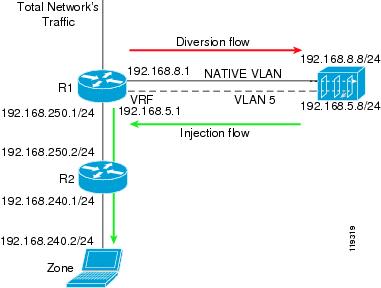
VPN Routing Forwarding Destination (VRF-DST) is a static forwarding method that is deployed in Layer 3 network topologies, where the Guard forwards the filtered traffic to the same router from which the traffic was diverted (Figure 4-4).
To enable the Guard to divert the zone's traffic from the router, the Guard modifies the zone's route in the router's routing table to make the Guard the best path to the zone.
An endless routing loop could occur if the router's routing table is not changed. Because the only entry for the traffic destined to the zone in the router's routing table is the Guard, the filtered traffic from the Guard is sent back to the Guard.
VRF-DST allows you to create another routing and forwarding table (called the VRF table) in addition to the main routing and forwarding tables. The additional routing table is configured to route traffic that is handled by the router's interface that faces the Guard.
Figure 4-4 VRF DST Forwarding Method
This section contains the following topics:
•
VRF-DST Configuration Guidelines
To configure VRF-DST on an inject-to router, configure two separate interfaces on the router's physical interface facing the Guard as follows:
•
•
Note
Guard VRF-DST Configuration
This section describes the Guard VRF-DST configuration. The configuration in the following examples refers to the network in Figure 4-4.
Native Interface Statements
The following example shows how to configure the in-band interface:
admin@GUARD-conf# interface giga1admin@GUARD-conf-if-giga1# ip address 192.168.8.8 255.255.255.0Interface VLAN Statements
The following example shows how to configure VLAN 5 on the in-band interface:
admin@GUARD-conf# interface giga1.5admin@GUARD-conf-if-giga1.5# ip address 192.168.5.8 255.255.255.0BGP Statements
You can enter the Guard router BGP configuration as described in the "Guard BGP Configuration" section.
Injection Configuration
The next-hop router in the example is R2 (see Figure 4-3). To configure traffic injection from the Guard to the zone, add a static route to the next-hop router.
You should configure the static route at the Guard's router configuration level.
The following example shows how to configure a static route for the zone's network (192.168.240.0/24) via the VLAN interface on R1, 192.168.5.1:
router(config)# ip route 192.168.240.0 255.255.255.0 192.168.5.1
Note
Creating a VRF Table
The following example shows how to create a VRF table on the inject-to router:
R7200(config)# ip vrf Guard-vrfR7200(config)# rd 100:1R7200(config)# route-target export 100:1R7200(config)# route-target import 100:1Interface Native VLAN Statements
The following example shows how to configure the Native VLAN on the divert-from router:
R7200(config)# interface fastEthernet1/0.1R7200(config-if)# encapsulation dot1Q 1 nativeR7200(config-if)# description << VLAN TO GUARD-DIVERSION >>R7200(config-if)# ip address 192.168.8.1 255.255.255.0R7200(config-if)# no ip directed-broadcastInterface VLAN 5 Statements
The following example shows how to configure the VLAN 5 interface on the inject-to router:
R7200(config)# interface fastEthernet 1/0.5R7200(config-if)# encapsulation dot1Q 5R7200(config-if)# description << VLAN TO GUARD-INJECTION >>R7200(config-if)# ip vrf forwarding Guard-vrfR7200(config-if)# ip address 192.168.5.1 255.255.255.0Interface to Zone Statements
The following example shows how to configure the router interface to the zone:
R7200(config)# interface fastEthernet 2/0R7200(config-if)# description << LINK TO ZONE >>R7200(config-if)# ip address 192.168.250.1 255.255.255.0BGP Statements
Enter the router, R1, BGP configuration as described in the "Cisco Router BGP Configuration" section.
Static VRF-DST Statements
The following example shows how to configure static VRF on the inject-to router. The static VRF specifies the route to the zone. The parameter global indicates that the inject-to router's VRF table receives a copy of next-hop properties (outbound interface, MAC address) from global routing table.
R7200(config)# ip route vrf Guard-vrf 192.168.240.2 255.255.255.0 192.168.250.2 globalPolicy-Based Routing VLAN Forwarding Method
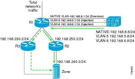
You can use the Policy-Based Routing VLAN (PBR-VLAN) method when there is more than one possible next-hop router (Figure 4-5). You configure multiple VLAN (Virtual LAN, 802.1Q) trunks between the Guard and router R1 (the divert-from and inject-to router). Each VLAN in the trunk is associated with a different next-hop router. In addition, you configure PBR on each VLAN logical interface to forward the traffic on the VLAN to its corresponding next-hop router.
The Guard forwards packets to a particular next-hop router by transmitting the packets over the appropriate VLAN. This action allows the Guard to change the next-hop router of a zone by changing the VLAN on which the packets are forwarded.
The native VLAN is used for traffic diversion. On this interface, the Guard sends the BGP announcements to the router.
Figure 4-5 PBR-VLAN Forwarding Method
This section contains the following topics:
•
Guard PBR-VLAN Configuration
This section describes the Guard PBR-VLAN configuration. The following examples refer to the network in Figure 4-5.
PBR-VLAN is applied on R1's interface facing the Guard. Zone traffic on VLAN-5 is forwarded to R2. Zone traffic on VLAN-6 is forwarded to R3.
Native Interface Statements
The following example shows how to configure the in-band interface:
admin@GUARD-conf# interface giga1admin@GUARD-conf-if-giga1# ip address 192.168.8.8 255.255.255.0Interface VLAN-5 Statements
The following example shows how to configure VLAN-5 on the in-band interface:
admin@GUARD-conf# interface giga1.5admin@GUARD-conf-if-giga1.5# ip address 192.168.5.8 255.255.255.0Interface VLAN-6 statements
The following example shows how to configure VLAN-6 on the in-band interface:
admin@GUARD-conf# interface giga1.6admin@GUARD-conf-if-giga1.5# ip address 192.168.6.8 255.255.255.0BGP Statements
You can enter the Guard router BGP configuration as described in the "Guard BGP Configuration" section.
Injection Configuration to R2
To configure traffic injection from the Guard to the zone, add a static route to the next-hop router R2.
You should configure the static route at the Guard's router configuration level.
The following example shows how to configure a static route for the zone's network (192.168.240.0/24) via the VLAN interface on R1, 192.168.5.1:
router(config)# ip route 192.168.240.0 255.255.255.0 192.168.5.1Injection Configuration to R3
You can configure traffic injection from the Guard to the zone by adding a static route to the next-hop router R3.
You should configure the static route at the Guard's router configuration level.
The following example shows how to configure a static route for the zone's network (192.168.240.0/24) via the VLAN interface on R1, 192.168.6.1:
router(config)# ip route 192.168.240.0 255.255.255.0 192.168.6.1Cisco Router PBR-VLAN Configuration
This section describes the Cisco router PBR-VLAN configurations.
Interface Native VLAN Statements
The following example shows how to configure the native VLAN for traffic diversion:
interface fastEthernet 1/0description << NATIVE VLAN TO GUARD-DIVERSION >>ip address 192.168.8.1 255.255.255.0no ip directed-broadcastVLAN-5 Creation
The following example shows how to create VLAN-5 on router R1:
interface fastEthernet 1/0.1encapsulation dot1Q 5description << VLAN-5 TO GUARD-INJECTION >>ip address 192.168.5.1 255.255.255.0ip policy route-map next-hop_R2no ip directed-broadcastVLAN-6 Creation
The following example shows how to create VLAN-6 on router R1:
interface fastEthernet 1/0.2encapsulation dot1Q 6description << VLAN-6 TO GUARD-INJECTION >>ip address 192.168.6.1 255.255.255.0ip policy route-map next-hop_R3no ip directed-broadcastNext-Hop Interface Configuration
The following example shows how to configure the interfaces to the next-hop routers:
interface fastEthernet 2/0ip address 192.168.250.1 255.255.255.0Description << LINK TO NEXT-HOP R2 >>exitinterface fastEthernet 3/0ip address 192.168.230.1 255.255.255.0description << LINK TO NEXT-HOP R3 >>BGP Statements
You can enter the router, R1, BGP configuration as described in the "Cisco Router BGP Configuration" section.
Route-Map Statements (PBR)
The following example shows how to configure PBR for the next-hop routers:
route-map next-hop_R2 permit 10set ip next-hop 192.168.250.2route-map next-hop_R3 permit 10set ip next-hop 192.168.230.2VPN Routing Forwarding VLAN Forwarding Method
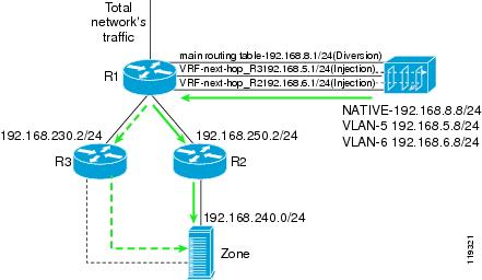
The VPN Routing Forwarding VLAN (VRF-VLAN) method is similar to the PBR-VLAN method. A VRF table is associated with each VLAN on the inject-to router rather than a PBR table. Each VRF table directs the traffic on the VLAN to the corresponding next-hop router (Figure 4-6).
The Guard forwards packets to a particular next-hop router by transmitting the packets over the appropriate VLAN. This action allows the Guard to change the next-hop router to the zone by changing the VLAN on which the packets are forwarded.
The native VLAN is used for traffic diversion. On this interface, the Guard sends the BGP announcements to the router.
Figure 4-6 VRF-VLAN Forwarding Method
This section contains the following topics:
•
Guard VRF-VLAN Configuration
This section describes the Guard VRF-VLAN configuration. The following examples refer to the network in Figure 4-6.
VRF-VLAN is applied on R1's interface facing the Guard. Zone traffic on VLAN-5 is forwarded to R2. Zone traffic on VLAN-6 is forwarded to R3.
Native Interface Statements
The following example shows how to configure the in-band interface:
admin@GUARD-conf# interface giga1admin@GUARD-conf-if-giga1# ip address 192.168.8.8 255.255.255.0Interface VLAN-5 Statements
The following example shows how to configure VLAN-5 on the in-band interface:
admin@GUARD-conf# interface giga1.5admin@GUARD-conf-if-giga1.5# ip address 192.168.5.8 255.255.255.0Interface VLAN-6 Statements
The following example shows how to configure VLAN-6 on the in-band interface:
admin@GUARD-conf# interface giga1.6admin@GUARD-conf-if-giga1.5# ip address 192.168.6.8 255.255.255.0BGP Statements
You can enter the Guard router BGP configuration as described in the "Guard BGP Configuration" section.
Set the neighbor IP address to 192.168.8.1.
Injection Configuration to R2
You can configure traffic injection from the Guard to the zone by adding a static route to the next-hop router R2.
You should configure the static route at the Guard's router configuration level.
The following example shows how to configure a static route for the zone's network (192.168.240.0/24) via the VLAN interface on R1, 192.168.5.1:
router(config)# ip route 192.168.240.0 255.255.255.0 192.168.5.1Injection Configuration to R3
You can configure traffic injection from the Guard to the zone by adding a static route to the next-hop router R3.
You should configure the static route at the Guard's router configuration level.
The following example shows how to configure a static route for the zone's network (192.168.240.0/24) via the VLAN interface on R1, 192.168.6.1:
router(config)# ip route 192.168.240.0 255.255.255.0 192.168.6.1Cisco Router VRF-VLAN Configuration
This section describes the Cisco router VRF-VLAN configurations.
First VRF Table Production
The following example shows how to create the VRF table associated with router R2:
ip vrf next-hop_R2rd 100:1route-target export 100:1route-target import 100:1Second VRF Table ProductionCreate the VRF table associated with router R3:ip vrf next-hop_R3rd 100:1route-target export 100:1route-target import 100:1Native VLAN Production
The following example shows how to configure the native VLAN on router R1:
interface fastEthernet 1/0description <<NATIVE VLAN TO GUARD-DIVERSION>>ip address 192.168.8.1 255.255.255.0no ip directed-broadcastVLAN-5 Creation
The following example shows how to create VLAN-5 on router R1:
interface fastEthernet 1/0.1encapsulation dot1Q 5description << VLAN-5 TO GUARD-INJECTION >>ip address 192.168.5.1 255.255.255.0ip vrf forwarding next-hop_R2no ip directed-broadcastVLAN-6 Creation
The following example shows how to create VLAN-6 on router R1 with the second VRF association:
interface fastEthernet 1/0.2encapsulation dot1Q 6description << VLAN-6 TO GUARD-INJECTION >>ip address 192.168.6.1 255.255.255.0ip vrf forwarding next-hop_R3no ip directed-broadcastNext-Hop Interfaces
The following example shows how to configure the interfaces to the next-hop routers:
interface fastEthernet 2/0ip address 192.168.250.1 255.255.255.0Description << LINK TO NEXT-HOP R2 >>!interface fastEthernet 3/0ip address 192.168.230.1 255.255.255.0description << LINK TO NEXT-HOP R3 >>BGP Statements
You can enter the router, R1, BGP configuration as described in the "Cisco Router BGP Configuration" section.
Static VRF Routes
The following example shows how to configure static VRF on the inject-to router. The static VRF specifies the route to the zone. The parameter global indicates that the route to the next hop is learned from the global routing table.
R7200(config)# ip route vrf next-hop_R3 192.168.240.2 255.255.255.255 192.168.230.2 globalR7200(config)# ip route vrf next-hop_R2 192.168.240.2 255.255.255.255 192.168.250.2 globalTunnel Diversion Forwarding Method
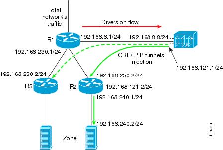
In the tunnel diversion method, a tunnel (GRE or IPIP) is created between the Guard and each of the next-hop routers (Figure 4-7). The Guard sends the traffic destined to the zone over the tunnel to the appropriate next-hop router. This action allows the Guard to change the next-hop router to a specified zone by changing the tunnel that the packets are forwarded on. Because the clean traffic from the Guard to the zone is encapsulated in the tunnel, the inject-to router performs a routing decision on the tunnel interface end point, not on the zone's address.
Figure 4-7 Tunnel Diversion Forwarding Method
This section contains the following topics:
•
•
Guard Tunnel Diversion Configuration
This section describes the Guard tunnel diversion configuration. The following examples refer to the network in Figure 4-7.
Native Interface Statements
The following example shows how to configure the in-band interface:
admin@GUARD-conf# interface giga1admin@GUARD-conf-if-giga1# ip address 192.168.8.8 255.255.255.0Tunnel Interface Statements
The following example shows how to configure a Generic Routing Encapsulation (GRE) tunnel.
admin@GUARD-conf# interface gre1admin@GUARD-conf-if-gre1# ip address 192.168.121.1 255.255.255.0admin@GUARD-conf-if-gre1# tunnel source 192.168.8.8admin@GUARD-conf-if-gre1# tunnel destination 192.168.250.2The following example shows how to configure an IP in IP (IPIP) tunnel.
admin@GUARD-conf# interface ipip1admin@GUARD-conf-if-ipip1# ip address 192.168.121.1 255.255.255.0admin@GUARD-conf-if-ipip1# tunnel source 192.168.8.8admin@GUARD-conf-if-ipip1# tunnel destination 192.168.250.2BGP Statements
You can enter the Guard router BGP configuration as described in the "Guard BGP Configuration" section.
Set the neighbor IP address to 192.168.8.1.
Injection Configuration
The next-hop router in the example is R2. To configure traffic injection from the Guard to the zone, add a static route to the next-hop router.
You should configure the static route at the Guard's router configuration level.
The following example shows how to configure a static route for the zone's network (192.168.240.0/24) via the tunnel interface on R1, 192.168.121.2:
router(config)# ip route 192.168.240.0 255.255.255.0 192.168.121.2Cisco Router Tunnel Diversion Configuration
Tunnel forwarding requires that you configure the router at the end of the tunnel (R2 in Figure 4-7). The diversion process requires that you configure the divert-from router (R1 in Figure 4-7).
R1 Diversion Configuration: BGP Statements
You can enter the router, R1, BGP configuration as described in the "Cisco Router BGP Configuration" section.
R2 Forwarding Configuration: Tunnel Interface on R2
The following example shows how to configure the tunnel on router R2:
interface tunnel 1description << GRE tunnel to Guard >>ip address 192.168.121.2 255.255.255.252load-interval 30tunnel source 192.168.250.2tunnel destination 192.168.8.8Long Diversion Method
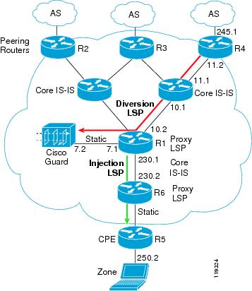
Unlike standard diversion techniques where the Guard diverts traffic only from an adjacent directly connected router, the long diversion method diverts traffic from remotely located peering routers that may reside several hops away from the Guard.
Figure 4-8 includes the following network elements:
•
•
•
•
Figure 4-8 Long Diversion Configuration
This section contains the following topics:
Packet Flow Example
The traffic flows to the zone's IP addresses (based on the loopback address that holds the Label Switched Path [LSP]).
Once an attack is identified, you activate the Guard to protect the attacked zone. The following steps automatically take place:
1.
2.
3.
4.
Long Diversion Configuration
The configuration in the following example refers to the network in Figure 4-8.
Guard Long Diversion Configuration
This section describes the Guard long diversion configurations.
Guard CLI Loopback Configuration
The following example shows how to add a loopback interface to the Guard:
admin@GUARD# configureadmin@GUARD-conf# interface lo:2admin@GUARD-conf-if-lo:2# ip address 1.1.1.1 255.255.255.255admin@GUARD-conf-if-lo:2# no shutdownadmin@GUARD-conf-if-lo:2# exitFor changes to take effect you need to reload the software.Type 'yes' to reload now, or any other key to reload manually lateryesreloading...Zebra CLI Loopback Configuration
The following example shows how to use the Zebra application to add a loopback interface to the routing configuration.
Note
router(config)# router bgp 100router(config-router)# redistribute Guardrouter(config-router)# bgp router-id 192.168.8.16router(config-router)# neighbor 192.168.8.1 remote-as 100router(config-router)# neighbor 192.168.8.1 description << iBGP session to peering Router >>router(config-router)# neighbor 192.168.8.1 soft-reconfiguration inboundrouter(config-router)# neighbor 192.168.8.1 route-map _new_next-hop outrouter(config-router)# exitrouter(config)# route-map _new_next-hop permit 10router(config-route-map)# set ip next-hop 1.1.1.1router(config)# ip route 0.0.0.0 0.0.0.0 192.168.7.1Cisco Router Long Diversion Configuration
This section describes the Cisco router long diversion configuration.
Peering Router Configuration (R2, R3, and R4)
The sample configuration in this section applies to the peering routers: R2, R3, and R4 (see Figure 4-8). This section displays only the commands relevant to long diversion configuration.
The following example shows how to configure Multiprotocol Label Switching (MPLS) on the peering routers:
mpls ipip cefThe following example shows how to configure the loopback 0 interface. This interface will be used to build the LSP via Intermediate System-to-Intermediate System (IS-IS).
interface Loopback 0ip address 3.3.3.3 255.255.255.255no ip directed-broadcastload-interval 30The following example shows how to configure the network connectivity interfaces:
interface fastEthernet 5/0ip address 192.168.11.2 255.255.255.0no ip directed-broadcastload-interval 30tag-switching ip (enable MPLS)no cdp enableThe following example shows how to configure IS-IS:
router isisredistribute static ipnet 49.0001.0000.0000.0003.00The following example shows how to configure iBGP to the Guard:
router(config)# router bgp 100R7200(config-router)# no synchronizationR7200(config-router)# bgp log-neighbor-changesR7200(config-router)# neighbor 192.168.8.16 remote-as 100R7200(config-router)# neighbor 192.168.8.16 description << iBGP to the Guard >>R7200(config-router)# neighbor 192.168.8.16 soft-reconfiguration inboundAdjacent Router Configuration (R1)
The sample configuration in this section applies to the adjacent router R1 (see Figure 4-8). This section displays only the commands relevant to long diversion configuration.
The following example shows how to configure the loopback 0 interface. This interface will be used to build the LSP via IS-IS.
interface Loopback 0ip address 2.2.2.2 255.255.255.255no ip directed-broadcastThe following example shows how to configure the network connectivity interfaces:
interface fastEthernet 5/0ip address 192.168.10.2 255.255.255.0no ip directed-broadcastload-interval 30tag-switching ip (enable MPLS)no cdp enableThe following example shows how to configure the interface to the Guard.
Note
interface FastEthernet1/0ip address 192.168.7.1 255.255.255.0no ip directed-broadcastThe following example shows how to configure the interface to the Guard.
Note
interface fastEthernet 0/1/1ip address 192.168.230.1 255.255.255.0tag-switching ip (enable MPLS)no cdp enableThe following example shows how to configure IS-IS:
router isisredistribute static ipnet 49.0001.0000.0000.0002.00The following example shows how to configure a static route on the egress proxy-LSR to the Guard loopback IP address (the IP address 1.1.1.1 is the loopback address configured on the Guard):
ip classlessip route 1.1.1.1 255.255.255.255 192.168.7.2