-
Cisco Guard Configuration Guide (Software Version 6.0)
-
Index
-
Preface
-
Product Overview
-
Initializing the Guard
-
Configuring the Guard
-
Configuring Traffic Diversion
-
Configuring Zones
-
Configuring Zone Filters
-
Configuring Policy Templates and Policies
-
Learning the Zone Traffic Characteristics
-
Protecting Zones
-
Using Interactive Protect Mode
-
Using Attack Reports
-
Using Guard Diagnostics Tools
-
Performing Maintenance Tasks
-
Analyzing Guard Mitigation
-
Understanding Zone Traffic Diversion
-
Troubleshooting Diversion
-
 Feedback
Table Of Contents
Understanding Zone Traffic Diversion
Understanding the Router Functions in Traffic Diversion
Understanding IP Traffic Diversion
Understanding the Traffic Forwarding Methods
Layer 2 Topology for Traffic Forwarding
Layer 3 Topology for Traffic Forwarding
Understanding the Layer 2 Forwarding Method
Understanding the Layer 3 Forwarding Methods
Policy-Based Routing-Destination
VPN Routing Forwarding-Destination
Using Tunnel Diversion to Forward Traffic
Diverting Traffic to the Guard
Using IGP to Determine the Next-Hop Router
Using IGP and BGP to Determine the Next-Hop Router
Blocking the Guard from Announcing Traffic/Updates
Understanding Zone Traffic Diversion
This chapter describes traffic diversion and provides detailed information about the traffic diversion methods that the Cisco Guard (Guard) uses in Layer 2 and Layer 3 topologies. The chapter also describes the long diversion and next-hop discovery methods.
This appendix contains the following major sections:
•
Understanding the Router Functions in Traffic Diversion
•
•
•
•
•
Understanding the Router Functions in Traffic Diversion
You place the Guard next to key routers in the network and when you activate the Guard to learn zone traffic or protect the zone, it diverts the traffic addressed to the zone from the routers to the Guard. When protecting a zone, the Guard analyzes and filters the zone traffic, removing the malicious packets from the diverted stream and forwarding the cleaned traffic to the main data path for delivery to the zone. The act of diverting traffic from the router is known as hijacking. The act of returning legitimate traffic to the network is known as injecting. The entire cycle (hijacking and injecting) is called the traffic diversion process. The following terminology is used in this appendix to describe the different functions of a router in the network:
•
•
•
•
Note
Understanding IP Traffic Diversion
IP traffic diversion consist of the following two tasks:
1.
2.
The Guard filtering arrays do not reside on the critical path. The Guard redirects the affected zone traffic only for processing and filtering. The Guard attack filtering capabilities are used to filter only the attacked sites within the zone while the legitimate traffic is allowed to flow directly to the zone.
This section contains the following topics:
Traffic Diversion Process
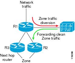
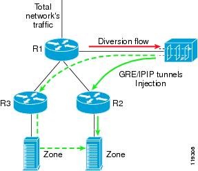
Traffic diversion (see Figure A-1) consists of the following two tasks:
1.
Figure A-1 Diversion Process
2.
Note
When multiple next-hop routers forward the traffic, the Guard determines which next-hop router to use to forward the traffic to the zone by a process called the next-hop discovery. Figure A-1 shows the traffic diversion process. The next-hop router to the zone could be either R2 or R3. The Guard performs the next-hop discovery process and learns which router to use (R2 in the figure).
When there is a single next-hop router only, the Guard chooses that router as the next-hop router. Due to routing changes, the current next-hop router to the zone may dynamically change. The Guard then selects the next-hop router by duplicating R1's selection of a next-hop router. The Guard acquires R1's next-hop router selection through the next-hop discovery process.
Layer 3 Topology
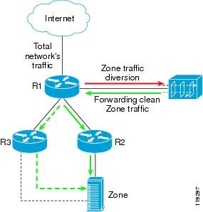
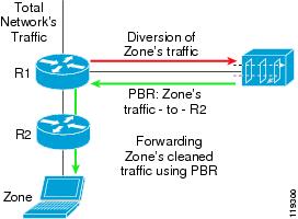
In a Layer 3 topology, the Guard is directly connected to the divert-from router R1 (see Figure A-2). The Guard receives the diverted traffic from R1, cleans it, and is ready to return the traffic back to R1 to forward the clean traffic to the zone. At this point, there is a danger of a closed loop between R1 and the Guard because R1 has the Guard as the addressee for any zone traffic. To avoid this loop, you must use a routing policy technique such as Policy Based Routing (PBR) or VPN Routing Forwarding (VRF) to enable the traffic to bypass R1's main routing table when R1 receives the traffic from the Guard. These routing policy techniques operate in a Layer 3 topology environment and are referred to as Layer 3 Forwarding (L3F) methods.
Figure A-2 Layer 3 Topology
The solid line indicates that R2 is the preferred next hop to the zone; however, the zone can also be accessed through R3. R1 functions as both a divert-from router and an inject-to router. R2 functions as a next-hop router while R3 also functions as the possible next-hop router.
Layer 2 Topology
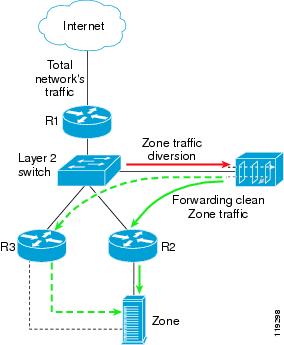
In a Layer 2 topology, the Guard is connected to a Layer 2 switch so that the divert-from router (R1), the next-hop router (R2) to the zone, and the Guard are located on the same LAN (see Figure A-3). The Guard locates the next-hop router (R2) by sending an Address Resolution Protocol (ARP) query to R2 IP address and forwards the clean zone's traffic directly to the router. The router forwards the traffic to the zone.
Figure A-3 Layer 2 Topology
The straight solid line to router R2 indicates the preferred next hop; however, it is also possible to reach the zone through R3.
In a Layer 2 topology, the inject-to router is the same as the next-hop router. Also in a Layer 2 topology, the divert-from router, next-hop router, and the Guard are in the same LAN.
Note
Long Diversion
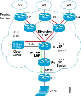
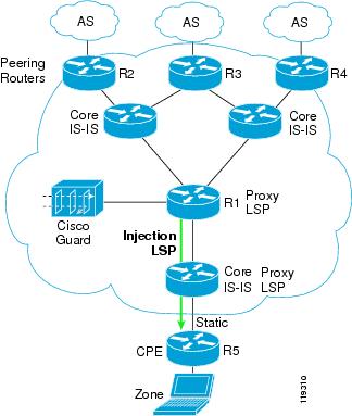
Unlike standard diversion techniques where the Guard diverts traffic from an adjacent router only, the long diversion method diverts traffic from remotely located peering routers that may reside several hops away from the Guard. Figure A-4 shows an overview of the long diversion method in a Multiprotocol Label Switching (MPLS) network.
Figure A-4 Using the Guard for Long Diversion
BGP Diverting Method
The Guard sends a BGP announcement to the divert-from router informing the router that the next hop to the zone is the Guard. The BGP announcement can be an external Boarder Gateway Protocol (eBGP) or an internal Boarder Gateway Protocol (iBGP) announcement. In order for the announcement to take precedence over any previous routing decision regarding the zone, the Guard sends the announcement with a longer, more specific prefix than the prefix that represents the zone in the divert-from router routing table.
To ensure that the announcement reaches the Guard's adjacent router only, the BGP announcement is sent with the no-advertise and no-export BGP community strings. Only the Guard's adjacent router receives the announcement. If a packet destined to the zone reaches a next-hop router, the router forwards that packet to the zone and not back to the Guard.
The Guard also adds a special string to the BGP announcement that specifies the Guard as the originator of the announcement. The Guard uses a community that is combined from the following two autonomous system (AS) numbers: AS-number-ISP and AS-number-guard, where the AS-number-guard is a private AS number.
One advantage of using BGP for the Guard's routing announcements is that the traffic diversion to the Guard stops automatically if the router loses communication with the Guard. Because the BGP keep-alive process automatically withdraws the prefixes from the router if the peer (Guard) has not responded to several keepalive messages for a certain amount of time.
Understanding the Traffic Forwarding Methods
This section describes how to forward the clean traffic from the Guard to the next-hop router. The methods vary according to the two main network topology scenarios: Layer 2 and Layer 3 topologies.
This section contains the following topics:
•
•
Layer 2 Topology for Traffic Forwarding
In a Layer 2 topology, the Guard, divert-from router, and next-hop router are on the same VLAN. In a Layer 2 topology, a divert-from router and an inject-to router are two different devices. The next-hop router and the inject-to router are the same device.
Layer 3 Topology for Traffic Forwarding
In a Layer 3 topology, the divert-from and inject-to routers are the same router (referred to as the router in this chapter). The Guard sends a BGP announcement that modifies the router's routing table to divert the zone traffic to the Guard. The Guard cleans the traffic and returns the cleaned traffic to the same router. The divert-from router then sends the traffic to the router that appears as the best path to the zone. This process may result in a malicious routing loop. You can avoid this loop by associating routing rules that override the router's routing table with the traffic that the Guard returns to the router. Use the following techniques to forward the packet without using the routing table and avoid traffic loops:
•
•
•
Note
The following three diversion methods depend on the next-hop router configuration; however, the next-hop router may be static for each zone or dynamically change:
•
•
Understanding the Layer 2 Forwarding Method
The L2F method is used in a network topology where the Guard, divert-from router, and next-hop router are on the same VLAN (see Figure A-3). In a Layer 2 topology, a divert-from router and an inject-to router are two different devices. The next-hop router and the inject-to router are the same device.
In the L2F method, the Guard resolves the MAC address of the inject-to/next-hop router and then forwards the traffic to that address. To resolve the MAC address, the Guard issues a standard ARP query for the IP address of the inject-to/next-hop router. When using the L2F method, no configuration on the routers is required.
Depending on a particular network configuration, a zone can be directly connected to a Layer 2 switch, which means that the zone is connected to the same LAN as the Guard. The Guard forwards the traffic directly to the zone because the zone IP address is configured as the inject-to router. If the traffic is sent to the protected zone through an IP forwarding device, the IP forwarding device must be defined as the Guard's next-hop device. See the "Layer-2 Forwarding Method" section on page 4-7 for more information.
Understanding the Layer 3 Forwarding Methods
This section describes the traffic forwarding methods that the Guard uses in a Layer 3 network topology.
This section contains the following topics:
•
•
•
•
Policy-Based Routing-Destination
The Policy-Based Routing-Destination (PBR-DST) method allow you to configure routing rules that are different from the rules configured in the router's routing table. You configure the PBR-DST rules only on the router's interface that faces the Guard. You perform the configuration once. A configured rule specifies that all traffic from the Guard to a zone is forwarded to the corresponding next-hop router. This process is a static next-hop discovery method. See the "PBR Destination Configuration Guidelines" section on page 4-9 for more information.
Figure A-5 PBR Forwarding Method
In Figure A-5, the PBR-DST method is applied to R1's interface facing the Guard to define a rule that specifies that all the zone traffic coming from the Guard is forwarded to R2.
VPN Routing Forwarding-Destination
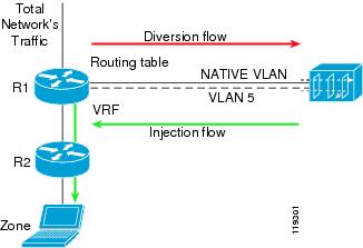
The VPN Routing Forwarding-Destination (VRF-DST) method (see Figure A-6) allows you to configure another routing and forwarding table (the VRF table) in addition to the main routing and forwarding tables.
The additional routing table is used only to route traffic that comes into the router's interface that faces the Guard. You configure two separate interfaces on the router's physical interface that faces the Guard. The first interface (the NATIVE VLAN) diverts traffic from the router to the Guard. Traffic on this VLAN is forwarded according to the global routing table. On this VLAN, the Guard sends the BGP announcements that divert the traffic to the Guard.
The second VLAN diverts the returned traffic from the Guard to the router. You configure a VRF table on the second VLAN. This table contains a static routing rule to forward all the zone traffic to a specific next-hop router. The VRF-DST method is also a static next-hop diversion method. Dynamic next hop diversion methods using VRF and PBR are described in the "Next-Hop Discovery" section. See the "Policy-Based Routing Destination Forwarding Method" section on page 4-9 for more information.
Figure A-6 VRF-DST Forwarding Method
The VRF-DST method is applied on the router interface that faces the Guard. You define a VRF table on this interface to contain a rule that routes all the zone's traffic coming from the Guard to R2.
Note
Policy-Based Routing VLAN
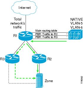
In the PBR VLAN method, you can configure a multiple VLAN (Virtual LAN, 802.1Q) trunk between the Guard and router R1 (see Figure A-7). You associate each VLAN in the trunk with a different possible next-hop router. In addition, you configure a PBR on each of the VLAN logical interfaces in the router side. Each PBR forwards all the traffic from a specific VLAN to its corresponding next-hop router. The Guard then forwards packets to a particular next-hop router by transmitting the packets over the appropriate VLAN to allow the Guard to change the next-hop router of a zone by changing the VLAN on which the packets are forwarded. In the figure, the NATIVE VLAN is used for the diversion of traffic (the Guard sends the BGP announcements on this interface to the router).
Figure A-7 PBR VLAN Forwarding Method
In Figure A-7, the PBR VLAN method is applied on R1's interface that faces the Guard. The traffic that comes over VLAN-5 is forwarded to R2 and the zone's traffic coming from the Guard over VLAN-6 is forwarded to R3. See the "Policy-Based Routing VLAN Forwarding Method" section on page 4-14 for more information.
VPN Routing Forwarding VLAN
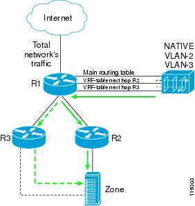
The VPN Routing Forwarding (VRF) VLAN method is the same as the PBR VLAN (see the "Policy-Based Routing VLAN" section) method except that you can associate a VRF table with each VLAN in the inject-to router instead of a PBR table. Each VRF table contains the rule that directs all the traffic that arrives on it to the corresponding next-hop router. The Guard then forwards packets to a particular next-hop router by transmitting the packets over the appropriate VLAN to allow the Guard to change the zone next-hop router by changing the VLAN that forwards the packets. In Figure A-8, the native VLAN is used for traffic diversion (on this interface, the Guard sends the BGP announcement). See Chapter 4, "Configuring Traffic Diversion" for more information.
Figure A-8 VRF-VLAN Forwarding Method
In Figure A-8, the VRF-VLAN method is applied on R1's interface that faces the Guard. Traffic that flows over VLAN-2 is forwarded to R2 and traffic that flows over VLAN-3 is forwarded to R3.
Using Tunnel Diversion to Forward Traffic
In the tunnel diversion method, you configure a tunnel between the Guard and each of the next-hop routers (see Figure A-9). The Guard sends the traffic over the tunnel that ends in the next-hop router of the destined zone. Because the returned traffic goes over a tunnel, the inject-to router performs a routing decision on the end point of the tunnel interface only, not on the zone's address.
Figure A-9 Tunnel Diversion
See the "Tunnel Diversion Forwarding Method" section on page 4-20 for more information.
Long Diversion Method
Unlike standard diversion techniques where the Guard diverts traffic only from a directly connected adjacent router, the long diversion method diverts traffic from remotely located peering routers that may reside several hops away from the Guard. The traffic to the zone is diverted from the peering points to the Guard over a tunnel such as GRE/IPIP or MPLS LSP. The regular forwarding method can inject the clean traffic back onto the network because the forwarding tables of R1 (attached to the Guard) and the other backbone routers are untouched.
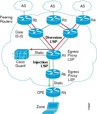
Figure A-10 shows how a diversion is implemented in an ISP backbone that implements MPLS. In the figure, R2, R3, and R4 are peering routers, while R1 is the router adjacent to the Guard.
Figure A-10 Guard Long Diversion
The long diversion process is divided into three parts:
•
•
•
Diverting Traffic to the Guard
Once an attack has been launched against a specific zone, the Guard sends out an iBGP announcement stating that in order to reach the zone, the traffic should route to the Layered Service Provider (LSP) that ends in the Guard's loopback address/interface. To ensure that the BGP announcements do not propagate into all the backbone routers' routing tables, the Guard attaches no-advertise and no-export BGP community strings to the BGP announcements. Only R2, R3, and R4 get the BGP announcement about the zone's (with a longer prefix) next hop that corresponds to the Guard's loopback interface.
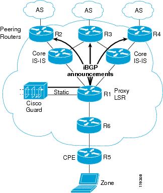
BGP Announcements
In the BGP announcement method, the Guard sends an iBGP announcement (with no-advertise and no-export) to routers R2, R3, and R4 informing them that the next hop to the zone is the Guard loopback interface. You set the next-hop attribute in the BGP announcement (using the route-map command in Cisco IOS software). The announcement uses a longer prefix then the original announcement of the zone and gets priority over the original BGP announcement.
Figure A-11 iBGP Announcement to the Peering Routers
MPLS LSP
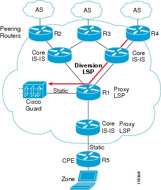
In the MPLS LSP method, after the iBGP announcement reaches the peering routers, the routers reroute the zone traffic to the LSP that extends from the peering points to the Guard loopback interface (see Figure A-12).
Figure A-12 MPLS LSP from the Peering Routers (R2, R3, R4) to the Guard
While the Guard is at the end of the LSP, the Guard does not have to support MPLS; it only receives pure IP (IP packets without an MPLS label) because R1 is the egress proxy LSP for the Guard. In other words, R1 performs one hop before the last-hop popping (removal of the MPLS label) on the MPLS packets that arrive at the Guard's loopback interface and delivers them directly to the Guard over the static route.
You should route the Guard's loopback address through IGP in the entire network by configuring R1 with a static route to the loopback address of the Guard. This process redistributes this static route with the IGP protocol (IS-IS in the example). The Guard does not run IS-IS.
Injecting Traffic to the Zone
After the Guard cleans the traffic, it injects the traffic back to R1 (see Figure A-13). In this scenario, it is assumed that R1 stores all routes to all the possible zones as if it was a peering router. R1 forwards the traffic to the zone using the suitable LSP.
Figure A-13 Injecting the Traffic to the Zone
The caveats and limitations for long diversion are as follows:
•
•
•
•
Next-Hop Discovery
When forwarding the traffic to the zone, the Guard should know which router is the next-hop router as determined by the divert-from router. Next-hop discovery is the process that the Guard runs in order to learn which router is the next-hop router. Because the next-hop router is the next hop to the zone (according to the divert-from router before diversion), the Guard should have the same view of the routing information that the divert-from router does. This routing information may include IGP and/or BGP information. The Guard should have the same neighbors that the divert-from router does. The Guard should receive all the routing protocols that the divert-from router runs in order to find the route to the zone. In some cases it would be enough to run only the IGP routing protocols, and in some cases it would require receiving the IGP and the BGP protocols. This solution applies only if the divert-from router uses a routing protocol to make its decision on how to route to the zone, instead of using static routes to the zones. If a static route is used, then the next hop route cannot be determined from the routing protocol (you should consider using a discovery by Telnet solution).
To receive the same IGP information as the divert-from router, you should connect the Guard by tunnels (GRE/IPIP) to the possible next-hop routers of the divert-from router.
To receive BGP information, the Guard need only be an iBGP neighbor of the divert-from router because with iBGP, the divert-from router announces its routing information to the Guard.
Caution
This section contains the following topics:
•
•
Using IGP to Determine the Next-Hop Router
The Guard learns the next-hop router only by receiving the IGP routing information in these situations:
•
•
The Guard supports only OSPF and RIP, because the Guard uses the Zebra routing-protocols software that supports only the above IGP protocols.
Figure A-14 shows how to receive IGP information.
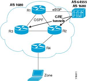
Figure A-14 Next-hop Discovery Leaning by IGP
Using IGP and BGP to Determine the Next-Hop Router
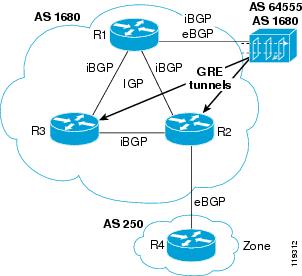
When the zone is in a different AS than the divert-from router, and BGP information is not redistributed to IGP, then the next-hop information to that zone is determined from both the IGP and BGP routing information. The divert-from router decides on the next hop in two phases. First, it learns the next BGP hop to the zone using BGP, and then it learns the actual next-hop router (interface) that leads to that next BGP peer from IGP (see Figure A-15).
Figure A-15 Next-hop Discovery Learning by IGP+BGP
To receive the BGP information of the divert-from router, the Guard receives the iBGP announcement from the divert-from router. The next-hop attribute is unaltered (the original next-hop is saved) in iBGP.
In this method, the two BGP daemons act as peers with the divert-from router. The first, the eBGP daemon (used for traffic diversion), and the second, the iBGP daemon (used for the next-hop discovery process).
To receive the same IGP information as the divert-from router, a third daemon which is the IGP daemon, is connected by tunnels to the possible next-hop routers of the divert-from router.
The Guard performs the same two-phase process as the divert-from router to establish the next hop to a zone. First, the Guard learns the next BGP hop router to the zone from BGP, and then it uses IGP to discover the route to the next-hop BGP router. In the figure, the Guard learns that the next hop to the zone is R4 and the IGP route to this interface.
Blocking the Guard from Announcing Traffic/Updates
The Guard participates in IGP and IBGP only to learn the next-hop router and it must not announce any routing information or receive any traffic in addition to the routing updates over the tunnel. To block the Guard from announcing traffic updates, follow these steps:
Step 1
Step 2
Step 3