Cisco CRS Carrier Routing System 8-Slot Line Card Chassis Unpacking, Moving, and Securing Guide
This guide provides instructions for unpacking the Cisco CRS 8-Slot Line Card Chassis (LCC) and its components, moving the chassis to its permanent location, and mounting the chassis in a rack. The companion document to this guide is Cisco CRS Carrier Routing System 8-Slot Line Card Chassis Site Planning Guide , which describes how to plan and prepare your site facilities for the installation of an 8-slot line card chassis.
The Cisco CRS 8-slot LCC is a half-height, rack-mounted 8-slot version of the 16-slot chassis. It is a highly scalable routing system that provides up to 6.4 terabits per second (Tbps) of routing capacity and supports up to 8 MSCs or FPs. The chassis installs in a 19-inch equipment rack.
The routing system consists of a single rack-mounted chassis that contains the system components:
- Modular services cards (MSCs) or forwarding processors (FP), also called line cards, (up to eight)
- Physical layer interface modules, or PLIMs, also called line cards, (up to eight, one for each MSC or FP) or SIPs/SPAs
- Route processor (RP) cards (up to two) or performance route processor (PRP) cards (up to two)
- Switch fabric cards (four required)
- A chassis midplane that connects MSCs or FPs to their PLIMs and to switch fabric cards
The Cisco CRS 8-slot LCC has its own power and cooling subsystems. Two types of power systems are available: fixed or modular configuration. Both power configurations use either AC or DC power.
The Cisco CRS 8-slot LCC supports 40 GB, 140 GB, and 200 GB fabric cards and line cards, as follows:
- The Cisco CRS-1 Carrier Routing System uses fabric cards designed for 40 GB operation (FC/S cards).
- The Cisco CRS-3 Carrier Routing System uses fabric cards designed for 140 GB operation (FC-140G/S cards).
- The Cisco CRS-X Carrier Routing System uses fabric cards designed for 200 GB operation (FC-400G/S cards in 200G mode).
 Caution |
A mixture of 40G, 140G, and 200G fabric cards is not a supported mode of operation. Such a mode is allowed temporarily only during the upgrade process. |
 Note |
Throughout this document, the generic term Cisco CRS Carrier Routing system refers to the Cisco CRS-1, Cisco CRS-3, and Cisco CRS-X Carrier Routing Systems, unless otherwise specified. |
Documentation Overview
This section presents the following topics:
Objective
This document provides instructions for unpacking the Cisco CRS 8-slot LCC and its components, attaching the dolly, moving the chassis safely to its final location, and installing the chassis in a rack. This document does not provide background information and basic theory-of-operation for anyone wanting to understand the Cisco CRS Carrier Routing System.
Audience
This document is intended for those who unpack the Cisco CRS 8-slot LCC and Cisco installation partners who are responsible for moving and securing the LCC. No additional knowledge of routing or the Cisco IOS XR software is assumed.
Related Documentation
For complete planning, installation, and configuration information, see the following documents:
Hardware Documents
- Cisco CRS Carrier Routing System 8-Slot Line Card Chassis Unpacking, Moving, and Securing Guide (this document)
- Cisco CRS-1 Carrier Routing System 8-Slot Line Card Chassis Site Planning Guide
- Cisco CRS Carrier Routing System 8-Slot Line Card Chassis System Description
- Cisco CRS Carrier Routing System 8-Slot Line Card Chassis Installation Guide
- Cisco CRS-1 Carrier Routing System to Cisco CRS-3 Carrier Routing System Migration Guide
- Cisco CRS Carrier Routing System Regulatory Compliance and Safety Information
Software Documents
For a complete listing of available software documentation for the Cisco CRS Carrier Routing System, see About Cisco IOS-XR Software Documentation, available online at:
http://www.cisco.com/en/US/products/ps5763/products_documentation_roadmaps_list.html
Changes to This Document
The following table lists the technical changes made to this document since it was first printed.
|
Date |
Change Summary |
|---|---|
|
January 2014 |
Added updates to support the Cisco CRS-X, which includes new line cards, switch fabric cards, and PLIMs. |
|
June 2011 |
Reorganized sections in this document. Updated unpacking information. Added performance route processor (PRP) card to the pallet contents listed in the Chassis Packaging section. |
|
March 2011 |
Updated unpacking information and graphics. Added CRS-1 and CRS-3 information. Also made minor editorial changes. |
|
October 2010 |
Updated the rack-mounting procedure to clarify the sequence and added information about new MSC-140G and CRS-FP-140G line cards. |
|
May 2008 |
In procedure Preparing to Mount the Chassis in a Rack, deleted a note identifying the location of screws used to reinstall the rear vertical mounting brackets. The screws are always shipped installed. |
|
July 2007 |
Added caution about our recommendation to not ship the chassis with MSCs or RPs installed in the chassis. |
|
April 2006 |
Added moving and securing information; reorganized the guide; removed some extraneous and duplicate sections; updated hardware documentation titles; updated several illustrations. |
|
December 2005 |
Updated to reflect new packaging. |
|
March 2005 |
Updated to include information on mounting the chassis in the rack from the rear. |
|
December 2004 |
Initial release of this document. |
Obtaining Documentation and Submitting a Service Request
For information on obtaining documentation, submitting a service request, and gathering additional information, see the monthly What’s New in Cisco Product Documentation, which also lists all new and revised Cisco technical documentation, at:
http://www.cisco.com/en/US/docs/general/whatsnew/whatsnew.html
Subscribe to the What’s New in Cisco Product Documentation as a Really Simple Syndication (RSS) feed and set content to be delivered directly to your desktop using a reader application. The RSS feeds are a free service and Cisco currently supports RSS version 2.0.
Chassis Unpacking Overview
This section contains the following topics:
Chassis Packaging
The Cisco CRS 8-slot line card chassis arrives packaged on several pallets (the number of pallets depends on the options you ordered) with each package containing a label that describes the contents. For complete details on the contents of your shipment, see the inventory and parts identification label on the crate as shown in the following figure. The total number of pallets depend on the details of the options you ordered with each package containing a label that describes the contents.
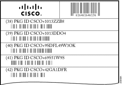
Note |
Crate numbering for chassis packaging is for reference only. This list is only a sample of what a CRS 8-slot chassis shipment contains. For complete details on the contents of each pallet, see the shipping and parts identification label on the pallet or shipping manifest. |
Primary system pallet (Crate 1): Contains the chassis encased in a polyethylene bag and covered with a corrugated primary shipper packing crate held together with plastic bands.
The chassis is shipped with the air filter already installed. The modular services card (MSC) and physical layer interface module (PLIM) slots are populated with blanks and impedance carriers. The switch fabric slot is shipped with a slot cover over it.
The primary system pallet also contains the fan tray and power distribution units (PDUs). The chassis is shipped with the air filter already installed.
Note |
The PDU fixed power shelf AC or DC is preinstalled in the chassis. The modular configuration AC or DC power shelves are shipped separately. |
- Card pallet (Crate 2): Contains the route processors (RP) or performance route processor (PRP) cards, rectifier, fixed power entry module (PEM), modular power module (PM), switch fabric cards, the MSCs, and any PLIMs.
- Primary card pallet (Crate 3): shipped only if the system is configured with 2-4 line cards and 2-4 PLIMs)
- Card pallet (Crate 4): shipped only if the system is configured with 5-8 line cards and PLIMs)
- Accessory kit:
- One fan tray is not installed in the chassis but included in the accessory kit
- Accessory and spare screws
- Rack shelf spacers (2)
- Pull handles (2)
The Cisco CRS 8-Slot line card chassis is shipped in a double-wall carton on a standard shipping pallet. Always transport the chassis in its original packaging and make sure that the system is transported and stored in an upright position. If you plan to store system components before the installation, be sure to store the components carefully and in their original shipping containers to prevent accidental damage.
Key Chassis Specifications
A newly received 8-slot line card chassis in its shipping carton and on a pallet has the following physical characteristics:
- 418.3 lb. (189.7 kg) chassis with shipping crate and pallet
- 330.8 lb. (138 kg) chassis with fans, PDUs, blanks, and impedance carriers (as shipped)
- Pallet length: 48 in. (121.3 cm)
- Pallet width: 37.12 in. (94.3 cm)
- Pallet height: 10.5 in. (26.6 cm)
- Shipping carton height: 50.87 in. (129.2 cm)
Caution |
Do not stack the 8-slot line card chassis shipping cartons, because serious damage to the components can occur. |
Safety Guidelines
Before you perform any procedure in this document, review the safety guidelines in this section to avoid injuring yourself or damaging the equipment.
The following guidelines are for your safety and to protect equipment. The guidelines do not include all hazards. Be alert.
- Keep the work area clear and dust-free during and after installation. Do not allow dirt or debris to enter into any laser-based components.
- Do not wear loose clothing, jewelry, or other items that could get caught in the router while working with MSCs, FPs, PLIMs, or their associated components.
- Cisco equipment operates safely when used in accordance with its specifications and product-usage instructions.
- Be sure to power down a fixed configuration PDU or modular configuration power shelf before removing it from the chassis.
- Do not work alone if potentially hazardous conditions exist.
Verifying the Securing Location
Verifying the recommended space also ensures that you have enough space available to perform the initial installation of the chassis and its components.
Before moving the chassis into position, make sure that you have properly prepared the site so that there is sufficient room for installation and maintenance.
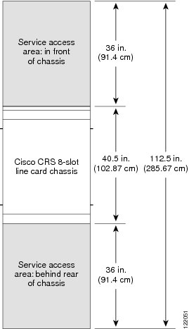
The floor plan for the Cisco CRS 8-slot line card chassis must include enough space to install the chassis in the equipment rack and allow sufficient airflow for the system. The floor plan must also provide enough room to access chassis components for maintenance (for example, to remove fan trays, power modules, cables, and air filters).
For chassis installation, make sure that enough room exists in front of the chassis to accommodate installation personnel and the lifting device used to hold the chassis in the rack while it is bolted to the rack.
The following figure shows the service area flooring in a lab from the top of the chassis.
For details on making your site ready for the chassis, see Cisco CRS Carrier Routing System 8-Slot Line Card Chassis Site Planning Guide.
Preventing Electrostatic Discharge
Electrostatic discharge (ESD) damage, which can occur when electronic cards or components are improperly handled, results in complete or intermittent failures. We recommend to use an ESD-preventive strap whenever you handle network equipment or one of its components.
Following are guidelines for preventing ESD damage:
- Always use an ESD-preventive wrist or ankle strap and ensure that it makes good skin contact. Connect the equipment end of the connection cord to an ESD connection socket on the router or to a bare metal surface on the chassis.
- Handle a card by its ejector levers, when applicable, or the card's metal carrier only; avoid touching the board or connector pins.
- Place a card removed from the chassis, component side up, on an antistatic surface or in a static-shielding bag. If you plan to return the component to the factory, immediately place it in a static-shielding bag.
- Avoid contact between the card and clothing. The wrist strap protects the board only from ESD voltage on the body; ESD voltage on clothing can still cause damage.
Unpacking the Cisco CRS 8-Slot Line Card Chassis
This section describes how to unpack the 8-slot line card chassis.
Caution |
Use the complete Cisco Systems packaging for shipment of product or components. Failure to properly use Cisco packaging may result in damage or loss of the product. |
The chassis is shipped on a pallet by itself and arrives inside a polyethylene bag enclosed in a corrugated box, held in place by plastic bands.
Prerequisites
Before performing this task, be sure to have sufficient room around the chassis pallet for unpacking. For information about the chassis dimensions, see Appendix A, Cisco CRS 8-Slot Line Card Chassis Specifications in Cisco CRS Carrier Routing System 8-Slot Line Card Chassis Installation Guide .
Steps
To unpack the 8-slot line card chassis, follow these steps:
SUMMARY STEPS
- Carefully move the pallet containing the 8-slot line card chassis to the staging area where you plan on unpacking it.
- Cut the plastic bands holding the chassis shipping box in place.
- Remove the accessory carton and remaining packing material (as shown in the figure below). Carefully set them aside.
- Using two people, lift the box straight up over the chassis as shown in the figure below.
- Leave the chassis on the pallet until you are ready to move and install the chassis in a rack.
DETAILED STEPS
| Step 1 |
Carefully move the pallet containing the 8-slot line card chassis to the staging area where you plan on unpacking it.
|
||
| Step 2 |
Cut the plastic bands holding the chassis shipping box in place. 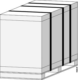 |
||
| Step 3 |
Remove the accessory carton and remaining packing material (as shown in the figure below). Carefully set them aside. 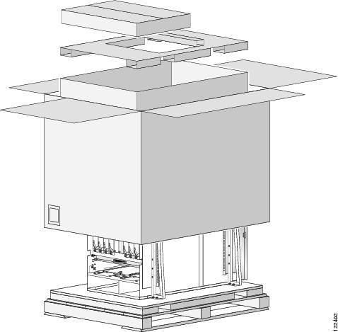 |
||
| Step 4 |
Using two people, lift the box straight up over the chassis as shown in the figure below. 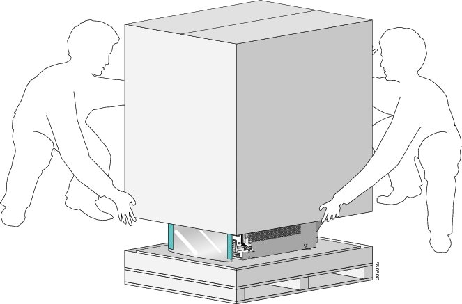 |
||
| Step 5 |
Leave the chassis on the pallet until you are ready to move and install the chassis in a rack.
|
What to do next
After performing this task, install rear pull handles, if you have a fixed configuration.
Installing the Rear Pull Handles
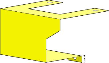
This section describes how to install the rear pull handles (for fixed configurations only). The rear pull handles provide additional handholds to aid you in moving the chassis, mounting the chassis into a rack, and unmounting the chassis. (See the figure below)
Note |
The rear pull handles must be installed on the chassis while it is still on the pallet. |
Required Tools and Equipment
You need the following tools and parts:
- Horizontal rack-mounting rails
- Equipment rack
- 10-mm hex wrench
- Rear pull handles (two are included in the installation kit, Cisco product number CRS-8-INSTALL-KIT=)
Steps
To install the rear pull handles, follow these steps:
SUMMARY STEPS
- Remove the rear pull handles from the packaging; two separate pulls exist for the rear of the chassis, one to cover each PDU.
- Remove the wooden block at the rear of the chassis that covers the PDUs (if necessary).
- Using the 10-mm hex wrench, remove the front two screws that fasten the top of the left PDU (as you face the rear (MSC) side of the chassis) to the PDU holding plate. Leave the rear two screws and PDU holding plate in place.
- Using the 10-mm hex wrench, remove the two screws that hold the front of the left PDU to the lip at the lower rear edge of the chassis.
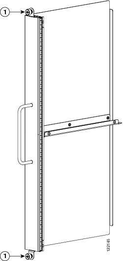
- Hold one rear pull handle in place over the left PDU (as you face the rear of the chassis). Starting with the top two screws, hand tighten the four screws that hold the pull handle to the chassis-PDU combination. The following figure shows the Cisco CRS 8-slot chassis with rear pull handles installed.
- Using the 10-mm hex wrench, tighten the screws so that the pull handles are firmly attached to the rear of the chassis.
- Repeat Step 2 through Step 7 with the other pull handle on the right PDU.
DETAILED STEPS
| Step 1 |
Remove the rear pull handles from the packaging; two separate pulls exist for the rear of the chassis, one to cover each PDU. |
||||||||
| Step 2 |
Remove the wooden block at the rear of the chassis that covers the PDUs (if necessary). |
||||||||
| Step 3 |
Using the 10-mm hex wrench, remove the front two screws that fasten the top of the left PDU (as you face the rear (MSC) side of the chassis) to the PDU holding plate. Leave the rear two screws and PDU holding plate in place. |
||||||||
| Step 4 |
Using the 10-mm hex wrench, remove the two screws that hold the front of the left PDU to the lip at the lower rear edge of the chassis. |
||||||||
| Step 5 |
Hold one rear pull handle in place over the left PDU (as you face the rear of the chassis). Starting with the top two screws, hand tighten the four screws that hold the pull handle to the chassis-PDU combination. The following figure shows the Cisco CRS 8-slot chassis with rear pull handles installed. 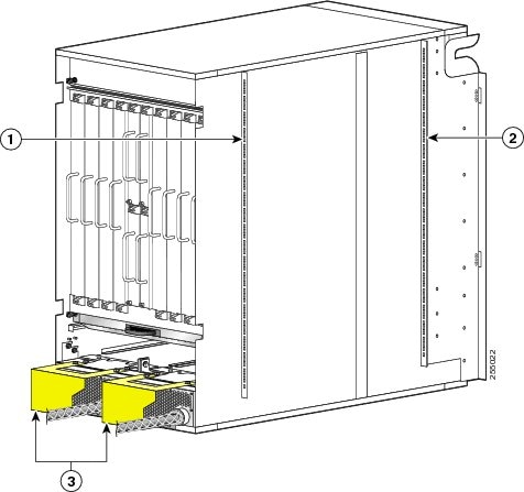
|
||||||||
| Step 6 |
Using the 10-mm hex wrench, tighten the screws so that the pull handles are firmly attached to the rear of the chassis. |
||||||||
| Step 7 |
Repeat Step 2 through Step 7 with the other pull handle on the right PDU. |
What to do next
After performing this task, remove the chassis from the pallet to a suitable lifting device. Use the pull handles for additional support in moving and mounting the chassis.
Removing the Chassis from the Pallet
This procedure describes how to remove the support brackets that secure the chassis to the pallet and then transfer the chassis to a lifting device. We recommend that at least two or three people perform this procedure.
Caution |
Exercise extreme caution during this procedure. The chassis is unstable when not secured to the pallet or rack. The chassis should always remain upright and should not be bumped or dropped. |
Required Tools and Equipment
You need the following tools to perform this task:
- Phillips #1 screwdriver
- 3/4-in. 6-point closed-end wrench
Steps
Note |
Do not remove the chassis support brackets until you are ready to move and install the chassis. |
To remove the chassis from the pallet and then transfer the chassis to a moving device, follow these steps:
SUMMARY STEPS
- Using a screwdriver, remove the six panhead M5 x10-mm screws (three screws at the bottom of the bracket and three at the top) that connect the right-front support bracket to the chassis. (See the following figure.)
- Using the 10-mm socket wrench, remove the two 3/4-in. bolts that connect the left front support bracket to the pallet.
- Set the support bracket aside carefully.
- Repeat Step 1 through Step 3 for the remaining three support brackets.
DETAILED STEPS
| Step 1 |
Using a screwdriver, remove the six panhead M5 x10-mm screws (three screws at the bottom of the bracket and three at the top) that connect the right-front support bracket to the chassis. (See the following figure.) 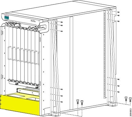 |
| Step 2 |
Using the 10-mm socket wrench, remove the two 3/4-in. bolts that connect the left front support bracket to the pallet. |
| Step 3 |
Set the support bracket aside carefully. |
| Step 4 |
Repeat Step 1 through Step 3 for the remaining three support brackets. |
Transferring the Chassis to a Mechanical Lifting Device
Caution |
Because of the high chassis weight (with fans, PDUs, blanks, and impedance carriers as shipped), you should not attempt to move or lift it without a mechanical lifting device. |
SUMMARY STEPS
- Place the mechanical lifting device in front of the chassis on the pallet (PLIM side) as shown in the figure below.
- Prepare to use the mechanical lifting device by placing a piece of cardboard on the surface of the lift (to prevent scratching).
- With at least two or three people move the chassis carefully from the pallet onto the lifting device as shown in the following figure.
DETAILED STEPS
| Step 1 |
Place the mechanical lifting device in front of the chassis on the pallet (PLIM side) as shown in the figure below. 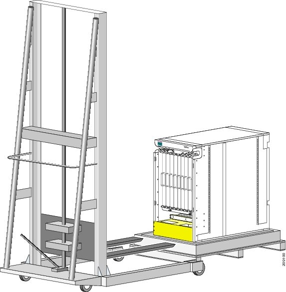 |
||||||||||||
| Step 2 |
Prepare to use the mechanical lifting device by placing a piece of cardboard on the surface of the lift (to prevent scratching). |
||||||||||||
| Step 3 |
With at least two or three people move the chassis carefully from the pallet onto the lifting device as shown in the following figure. 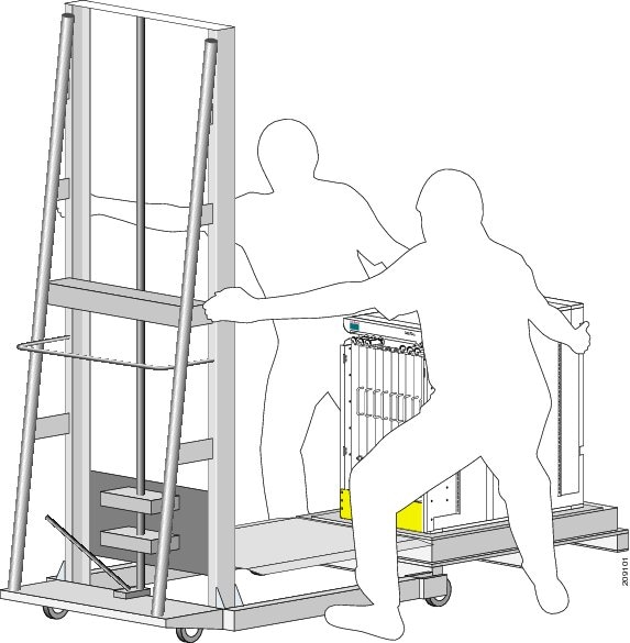
The following figure shows the location of the cable management trough on the PLIM side of the chassis. 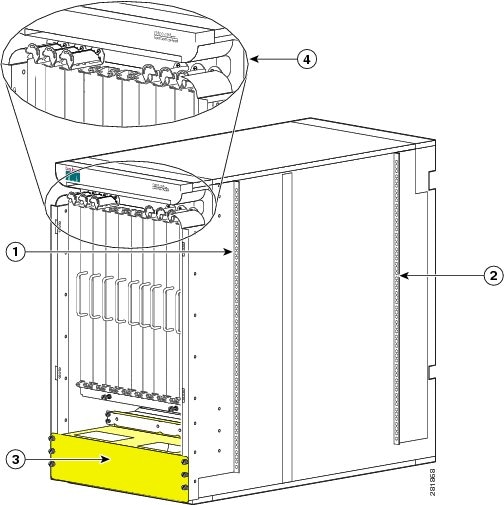
|
What to do next
After performing this task, move the chassis to its final location.
Moving the Cisco CRS 8-Slot Line Card Chassis
This section describes the procedures required to move the Cisco CRS 8-Slot line card chassis to its final location. This section contains the following topics:
Note |
The installation of a Cisco CRS 8-Slot line card chassis may require space, floor loading, power, and cooling modifications to your facility. Site planning should have been performed well in advance of the scheduled delivery of your system. See the Cisco CRS Carrier Routing System 8-Slot Line Card Chassis Site Planning Guide . |
Moving Guidelines for the 8-Slot Line Card Chassis
We recommend that at least two or three people move the as-shipped chassis from the shipping dock to the installation site. We also recommend that you leave the as-shipped chassis attached to its pallet for moving. Follow these guidelines:
- Chassis installation location must be identified.
- Packaging should be removed while leaving the chassis firmly secured to the pallet.
Note |
To ensure that the chassis has proper access to the installation location, see Cisco CRS Carrier Routing System 8-Slot Line Card Chassis Site Planning Guide . |
- Identify the type of suitable moving device that will be used to move the as-shipped chassis from the loading dock or staging area to the installation site.
- Make certain all doorways and hallways are wide and tall enough for the moving the as-shipped chassis. The 8-slot chassis needs an aisle of approximately 60 inches in width to be turned while on a fork lift.
- Make sure that you have at least one person on each side of the chassis.
-
When transporting the as-shipped chassis on a ramp
, follow these guidelines:
- Make sure that you have at least two or three people to transport the chassis up and down a ramp. One person in the rear pushing, one person at the front pulling, and one steering the chassis.
- Exercise extreme caution when moving chassis up an incline of any angle.
Caution |
If the route to the installation site has any ramps, use a moving device other than a scissor lift to move the chassis over the ramps, and then transfer the chassis onto a suitable lifting device such as a scissor lift for installation. Leave the blanks and impedance carriers in place in empty card slots while you move or install the chassis in the rack. The blanks and impedance carriers provide support to keep the chassis square during movement and installation. |
Moving the Chassis to the Final Location
This section describes how to move the as-shipped 8-slot line card chassis. The 8-slot chassis is shipped preinstalled with four vertical rack mounting rails for installing the chassis. For stability and support, leave the mounting brackets installed when you move the chassis.
Caution |
The chassis is shipped with blanks and impedance carriers installed or slot covers installed over all slots. Leave these in place to maintain chassis stiffness and integrity during moving. |
To move the 8-slot chassis to its installation location, follow these steps:
SUMMARY STEPS
- Make sure you have a suitable lifting device to move the Cisco CRS 8-Slot Line Card Chassis.
- Move the chassis to its installation location.
DETAILED STEPS
| Step 1 |
Make sure you have a suitable lifting device to move the Cisco CRS 8-Slot Line Card Chassis. |
| Step 2 |
Move the chassis to its installation location. |
What to do next
After moving the chassis to the room or area where you will install it, begin the procedure to mount the chassis into the rack.
Preparing the Rack for Chassis Installation
Install the Cisco CRS 8-Slot line card chassis into a four-post 19-in. standard rack with standard horizontal mounting rails.
For more detailed information about rack requirements for the Cisco CRS 8-Slot line card chassis, see the Equipment Rack Specifications section in Chapter 3 of Cisco CRS Carrier Routing System 8-Slot Line Card Chassis Site Planning Guide .
Before you move the chassis or mount the chassis into the rack, we recommend that you do the following:
SUMMARY STEPS
- Place the rack where you plan to install the Cisco CRS 8-Slot line card chassis.
- Secure the rack to the floor.
DETAILED STEPS
| Step 1 |
Place the rack where you plan to install the Cisco CRS 8-Slot line card chassis. |
||
| Step 2 |
Secure the rack to the floor.
To bolt the rack to the floor, a floor bolt kit (also called an anchor embedment kit ) is required. For information on bolting the rack to the floor, consult a company that specializes in floor mounting kits (such as Hilti; see Hilti.com for details). Make sure that floor mounting bolts are accessible, especially if annual retorquing of bolts is required. |
Removing the Rear Vertical Mounting Brackets
Remove the rear vertical mounting brackets temporarily because the chassis, with the rear vertical mounting brackets attached, cannot be installed into the rack from the front. The chassis must be positioned into the rack. Reattach them after the chassis has been positioned into the rack with the original mounting hardware.
Required Tools and Equipment
You need the following tools and parts to perform this task:
- Phillips #1 screwdriver
- 7-mm hex wrench
To remove the rear vertical mounting bracket from the chassis, follow these steps:
SUMMARY STEPS
- Use the Phillips #1 screwdriver to remove the inside screws.
- Use the 7-mm hex wrench to remove the outside screws (six for each bracket and one hidden screw) that hold the rear side chassis vertical mounting brackets (right side bracket and left side bracket) to the chassis. (See the figure below.)
- Remove the two vertical mounting brackets, and set them aside, along with their screws (six for each side).
- Remove MSC impedance carriers and two fasteners and set them aside. They should not be replaced until the chassis installation is complete.
DETAILED STEPS
| Step 1 |
Use the Phillips #1 screwdriver to remove the inside screws.
|
||||||||
| Step 2 |
Use the 7-mm hex wrench to remove the outside screws (six for each bracket and one hidden screw) that hold the rear side chassis vertical mounting brackets (right side bracket and left side bracket) to the chassis. (See the figure below.) 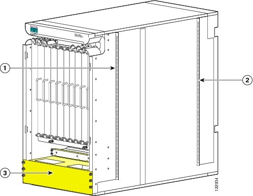
|
||||||||
| Step 3 |
Remove the two vertical mounting brackets, and set them aside, along with their screws (six for each side). |
||||||||
| Step 4 |
Remove MSC impedance carriers and two fasteners and set them aside. They should not be replaced until the chassis installation is complete.
|
What to do next
After you have mounted the chassis into the rack and removed the rear vertical mounting brackets from the chassis, install the horizontal mounting rails.
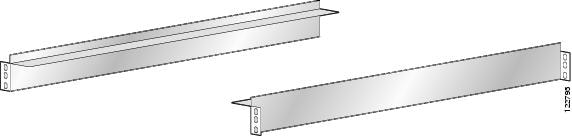
Installing the Horizontal Mounting Rails
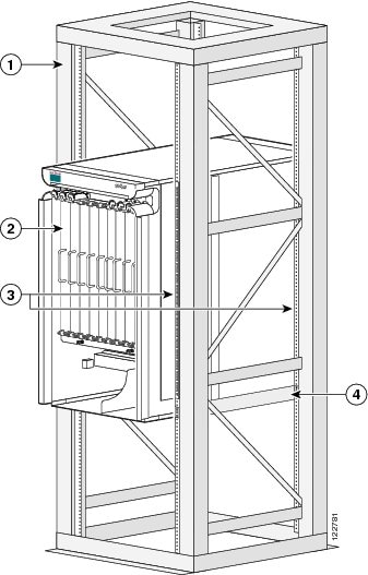
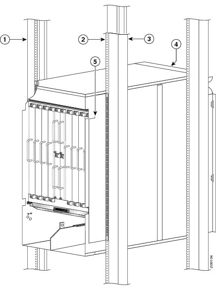
If you are installing a single chassis in a rack, the chassis must go in the middle or bottom portion of the rack or follow your company chassis mounting practices, as shown in the following figure.
|
1 |
Equipment rack |
3 |
Vertical mounting rails |
|
2 |
Cisco CRS 8-slot chassis |
4 |
Horizontal mounting brackets |
If you are installing two chassis in a rack, install the upper chassis first (see below the Two 8-Slot Chassis Mounted In Rack figure). To install the horizontal mounting rails, follow these steps:
SUMMARY STEPS
- If you are using a rack that came shipped with Cisco horizontal mounting rails preinstalled, remove these rails to allow for installation of the rails at the height you require.
- Determine the height at which you want the rails located in the rack.
- If necessary, adjust vertical equipment rack rails to handle the depth of the horizontal mounting bracket.
- Attach the horizontal rack mount bracket at the desired height. Make certain to tighten the vertical rail bolts after the horizontal rack rails are installed.
- Using the 12 Phillips screws—six screws for each rail (three screws in the front and three in the back)—attach the rails to the rack at the desired height.
- If you are mounting two chassis in a single rack, attach two additional horizontal mounting rails to the top of the rack, parallel to the attached horizontal mounting rails (to maintain a proper depth spacing of 22.8 inches for the chassis on the rack). The following figure shows two Cisco CRS 8-Slot chassis mounted in one equipment rack.
- Secure all bolts and screws. Once both sides are secured, you can transfer the chassis.
DETAILED STEPS
| Step 1 |
If you are using a rack that came shipped with Cisco horizontal mounting rails preinstalled, remove these rails to allow for installation of the rails at the height you require. |
||||||||
| Step 2 |
Determine the height at which you want the rails located in the rack.
 |
||||||||
| Step 3 |
If necessary, adjust vertical equipment rack rails to handle the depth of the horizontal mounting bracket. |
||||||||
| Step 4 |
Attach the horizontal rack mount bracket at the desired height. Make certain to tighten the vertical rail bolts after the horizontal rack rails are installed. |
||||||||
| Step 5 |
Using the 12 Phillips screws—six screws for each rail (three screws in the front and three in the back)—attach the rails to the rack at the desired height. |
||||||||
| Step 6 |
If you are mounting two chassis in a single rack, attach two additional horizontal mounting rails to the top of the rack, parallel to the attached horizontal mounting rails (to maintain a proper depth spacing of 22.8 inches for the chassis on the rack). The following figure shows two Cisco CRS 8-Slot chassis mounted in one equipment rack. 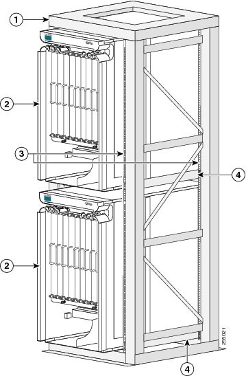
|
||||||||
| Step 7 |
Secure all bolts and screws. Once both sides are secured, you can transfer the chassis.
|
What to do next
After installing the horizontal mounting rails on the rack, prepare to mount the chassis in a rack.
Preparing to Mount the Chassis in a Rack
Before you mount the 8-slot chassis into a rack, it is critical that the installation site be prepared properly to handle the chassis weight, power requirements, cooling needs, and other requirements.
Because a fully-configured chassis weight can be up to 650 lb (294.84 kg), you should review the rack specifications from the manufacturer to determine whether the racks you have are appropriate to handle the weight of the chassis. See the “Equipment Rack Specifications” section in Chapter 3 of Cisco CRS Carrier Routing System 8-Slot Line Card Chassis Site Planning Guide .
- For complete details on site preparation and details about racks and any preparations you need to make at your site for mounting the chassis, see the Cisco Carrier Routing System 8-Slot Line Card Chassis Site Planning Guide .
- For specifications on the chassis, see Appendix A, Cisco CRS 8-Slot Line Card Chassis Specifications , in the Cisco CRS Carrier Routing System 8-Slot Line Card Chassis Installation Guide .
Caution |
To avoid tipping the chassis and possible injury when installing or servicing it, take care to properly position the chassis in the rack when you are mounting it. |
To accommodate equipment racks with different mounting hole patterns, the chassis mounting brackets have groups of screw holes on either side. (See the figure below.)
The mounting holes in the chassis mounting brackets are spaced so that one mounting hole in each hole group aligns with a corresponding hole in the equipment rack or the optional center-mount bracket. By using the corresponding mounting hole (in the same hole group) on the opposite side of the chassis, you can level the chassis in the rack.
To accommodate different site requirements, the chassis can be mounted in a rack with either the front (PLIM) side or rear (MSC) side facing out. We recommend that the chassis be mounted with the front side facing out as shown in the above figure.
Caution |
When you are installing the chassis in a rack, leave the PLIM impedance carriers in place to provide the chassis with enough support to keep it square during the procedure. However, the MSC impedance carriers should not be replaced until the chassis installation is complete. |
Caution |
Because of the chassis size and weight, it is unsafe to lift the chassis without mechanical assistance. |
Mounting the Chassis Into a Rack
This section describes how to mount the Cisco CRS Carrier Routing System 8-Slot Line Card Chassis into a standard 19-inch rack with the front (PLIM) side of the chassis facing out (in other words, by sliding the rear (MSC) side of the chassis into the rack first). Use only a four-post rack that matches the mounting specifications required for the chassis.
For more detailed information about rack types and preparations required for mounting the chassis at your site, see the information in http://www.cisco.com/en/US/docs/routers/crs/crs1/8_slot/requirement/guide/siteplan.html Planning a Cisco CSR-1 Series Carrier Routing System Site.
Caution |
On the PLIM side, no components should be removed at any time unless it is installed in a rack and is to be replaced by a functioning PLIM. |
Caution |
On the MSC side, blanks and impedance carriers need to be removed to remove rack mounting brackets. After the chassis and the mounting bracket are installed, the blanks and impedance carriers should be re-installed. |
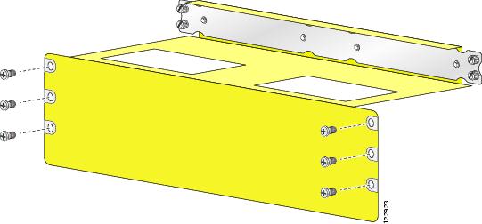
The following figure shows the chassis mounting hardware ready for rack mounting.
|
1 |
Two front chassis vertical mounting brackets |
3 |
Front pull handle (preinstalled) |
|
2 |
Two rear vertical side mounting brackets |
Prerequisites
Before performing this task, make sure that the rack is level and bolted to the floor.
Required Tools and Equipment
You need the following tools and parts to perform this task:
- Suitable transport device
- Phillips #1 screwdriver, 6-in. long and 8-in. long
- 10-mm and 7-mm hex wrench
- Mechanical lifting device, such as a scissor lift or other suitable lifting device
- Installation kit, shipped with the chassis, (contains horizontal mounting brackets and screws) (Cisco product number CRS-8-INSTALL-KIT=)
Steps
To mount the chassis on the rack with the front (PLIM) side facing out, follow these steps:
SUMMARY STEPS
- With the chassis on the lift, align the chassis with the rack.
- Using your mechanical lift, raise the chassis to the height of the rack’s horizontal mounting rails.
- Move the chassis. With at least two or three people:
- Move the lift aid away from the front of the chassis.
- Use the front pull handle to push carefully until the front vertical mounting brackets contact the rack mounting bracket with the vertical rack posts and someone in the rear guiding the chassis into the rack.
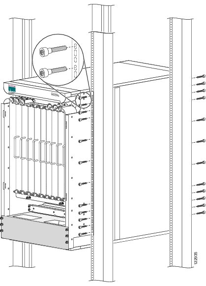
- Use the 7-mm hex wrench to reattach the rear (MSC) side vertical mounting brackets to the rear of the chassis. (See the figure below.)
- Insert and partially tighten the 48 screws —12 on each edge—to attach the chassis vertical mounting brackets to the rack vertical mounting brackets. (See the figure below.)
- Use the 7-mm hex wrench to fully tighten the screws.
- Re-install MSC impedance carriers.
DETAILED STEPS
| Step 1 |
With the chassis on the lift, align the chassis with the rack. |
||||||||||||||
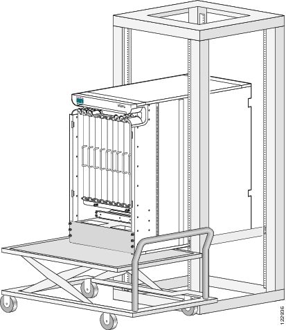
| Step 2 |
Using your mechanical lift, raise the chassis to the height of the rack’s horizontal mounting rails. As an example of a suitable lifting device, the following figure shows a scissor lift raising the chassis.
 |
||||||||||||||
| Step 3 |
Move the chassis. With at least two or three people:
|
||||||||||||||
| Step 4 |
Move the lift aid away from the front of the chassis. |
||||||||||||||
| Step 5 |
Use the front pull handle to push carefully until the front vertical mounting brackets contact the rack mounting bracket with the vertical rack posts and someone in the rear guiding the chassis into the rack. |
||||||||||||||
| Step 6 |
Use the 7-mm hex wrench to reattach the rear (MSC) side vertical mounting brackets to the rear of the chassis. (See the figure below.)
|
||||||||||||||
| Step 7 |
Insert and partially tighten the 48 screws —12 on each edge—to attach the chassis vertical mounting brackets to the rack vertical mounting brackets. (See the figure below.)
|
||||||||||||||
| Step 8 |
Use the 7-mm hex wrench to fully tighten the screws. |
||||||||||||||
| Step 9 |
Re-install MSC impedance carriers. |
What to do next
After performing this task, remove the rear pull handles the front pull handles.
Removing the Rear Pull Handles
This section describes how to remove the rear pull handles for fixed configurations only. The pull handles provide additional handholds to aid you in moving, mounting, and unmounting the chassis. (See the following figure.)
Prerequisites
Before performing this task, make sure that the chassis is installed and secured in the rack.
Required Tools and Equipment
You need the following tools to perform this task:
- 10-mm hex wrench
Note |
Use of pull handle is only used for fixed configurations. For modular configurations, pull handles are not used. |
Steps
To remove a rear pull handle, which is installed on the chassis in the area of the PDU, follow these steps:
SUMMARY STEPS
- Using the 10-mm hex wrench, loosen the four screws holding the right rear pull handle (as you face the rear MSC side of the chassis) to the chassis. Repeat this step for the left pull handle.
- Holding the right pull handle in place, use your hand to remove the four screws from the pull handle. Carefully set the pull handle aside. Repeat this step for the left pull handle.
- Replace the eight screws (four for each PDU) that connect the PDU to the chassis.
DETAILED STEPS
| Step 1 |
Using the 10-mm hex wrench, loosen the four screws holding the right rear pull handle (as you face the rear MSC side of the chassis) to the chassis. Repeat this step for the left pull handle. |
| Step 2 |
Holding the right pull handle in place, use your hand to remove the four screws from the pull handle. Carefully set the pull handle aside. Repeat this step for the left pull handle. |
| Step 3 |
Replace the eight screws (four for each PDU) that connect the PDU to the chassis. |
Removing the Front Pull Handle
This section describes how to remove the front pull handle. The pull handle provides additional handholds to aid you in moving, mounting, and unmounting the chassis and is installed on the chassis when it is shipped. (See the following figure.)
Prerequisites
Before performing this task, make sure that the chassis is installed and secured in the rack.
Required Tools and Equipment
You need the following tools to perform this task:
- Phillips #1 screwdriver
Steps
To remove the front pull handle, follow these steps:
SUMMARY STEPS
- Using the screwdriver, fully loosen all ten screws connecting the pull handle to the chassis.
- Remove the pull handle from the front of the chassis and set it aside carefully.
DETAILED STEPS
| Step 1 |
Using the screwdriver, fully loosen all ten screws connecting the pull handle to the chassis. |
| Step 2 |
Remove the pull handle from the front of the chassis and set it aside carefully. |
What to do next
After performing this task, you need to unpack remaining chassis components. See the next section and then go to the Cisco CRS Carrier Routing System 8-Slot Line Card Chassis Installation Guide to locate the installation instructions for the individual components.
Unpacking Chassis Component Shipping Pallets
The remaining shipping boxes and pallets are now ready to be delivered from receiving/shipping dock to the final location of the chassis.
Steps
To unpack the pallets, follow these steps:
SUMMARY STEPS
- If possible, move the pallets to the same location as the unpacked and secured chassis. If not possible, move the individual boxes containing the various components to the chassis location.
- Unpack all primary pallet parts from the packaging, and set the parts carefully aside for installation.
- Unpack all secondary pallet parts from packaging, and set the parts carefully aside for installation.
- Unpack all power components from the packaging, and set the parts carefully aside on an electrostatic discharge (ESD)-immune surface for installation.
- Unpack all cosmetic parts from the packaging and set the parts carefully aside
DETAILED STEPS
| Step 1 |
If possible, move the pallets to the same location as the unpacked and secured chassis. If not possible, move the individual boxes containing the various components to the chassis location.
|
||
| Step 2 |
Unpack all primary pallet parts from the packaging, and set the parts carefully aside for installation.
|
||
| Step 3 |
Unpack all secondary pallet parts from packaging, and set the parts carefully aside for installation.
|
||
| Step 4 |
Unpack all power components from the packaging, and set the parts carefully aside on an electrostatic discharge (ESD)-immune surface for installation. |
||
| Step 5 |
Unpack all cosmetic parts from the packaging and set the parts carefully aside |
Returning Product Components
Before preparing to return the product or product components, you must contact Cisco technical support and provide them with the details of your difficulty. Technical support needs to confirm your product or component failure before assigning an RMA number for return shipment. For additional information, see the Obtaining Documentation and Submitting a Service Request.
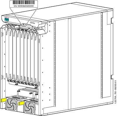
To facilitate your conversation with technical support, locate and note the serial number of your chassis. The serial number label for the line card chassis is located on the front (PLIM) side between the upper PLIM card slots and cable management bracket. (See the following figure.)
This document is to be used in conjunction with the documents listed in the Objective section.
 Feedback