Cisco Indoor Swivel-mount Dipole Antenna (ANT-4G-DP-IN-TNC)
This document provides the antenna specifications and mounting instructions for the Cisco Indoor Swivel-mount Dipole 3G/4G Antenna supported on the Connected Grid Router 1120 and is designed to support Cellular/PCS/AWS/MDS, WiMAX 2100/2300/2500/2600 and global GSM900/GSM1800/UMTS/LTE2600 bands.

This chapter covers the following topics:
- Technical Specifications
- Installation Requirements
- Safety Warnings
- Antenna Installation
- Obtaining Documentation and Submitting a Service Request
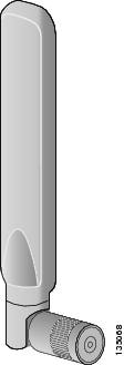
Figure 8-1 Swivel-mount Indoor Dipole Antenna
Technical Specifications
- Low-profile blade style sheath
- Applicable for both 3G and 4G solutions
- Domestic LTE 700 and global LTE 2600 bands
- Domestic cellular and global GSM
- Conformance to RoHS
- Complete cellular and 3G/4G data communications in a single antenna
- Articulating arm that allows antenna positioning to provide maximal coverage
RF Specifications
|
|
|
|---|---|
Mechanical Specifications
|
|
|
|---|---|
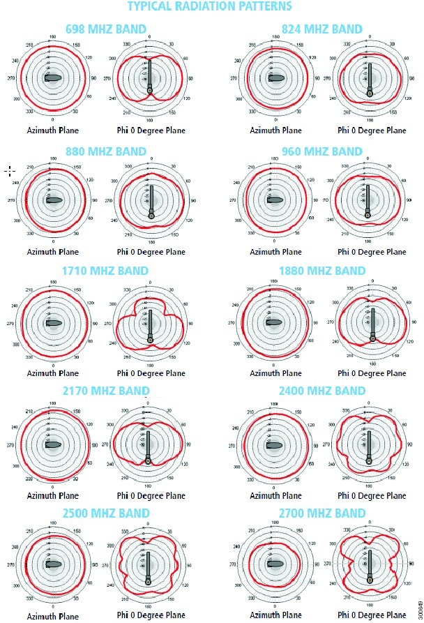
Radiation Patterns
Figure 8-2 Swivel-mount Dipole Antenna Radiation Patterns
Installation Requirements
Installation Location
Antenna installation and replacement should only be performed at one of the following, certified location types:
Antenna Connections
Before you install or replace antennas, make sure the router is:
For Optimum Performance
Antennas transmit and receive radio signals which are susceptible to RF obstructions and common sources of interference that can reduce throughput and range of the device to which they are connected. Follow these guidelines to ensure the best possible performance:
- Install the antenna vertically and mount it with the cables pointing towards the ground.
- Keep the antenna away from metal obstructions such as heating and air-conditioning ducts, large ceiling trusses, building superstructures, and major power cabling runs. If necessary, use a rigid conduit to lower the antenna away from these obstructions.
- The density of the materials used in surrounding buildings’ construction impacts antenna signal strength. Consider the following
–![]() Signals penetrate paper and vinyl walls with little change to signal strength.
Signals penetrate paper and vinyl walls with little change to signal strength.
–![]() Signals penetrate only one or two solid and pre-cast concrete walls without degrading signal strength.
Signals penetrate only one or two solid and pre-cast concrete walls without degrading signal strength.
–![]() Signals penetrate three or four concrete and wood block walls without degrading signal strength.
Signals penetrate three or four concrete and wood block walls without degrading signal strength.
–![]() Signals penetrate five or six walls constructed of drywall or wood without degrading signal strength.
Signals penetrate five or six walls constructed of drywall or wood without degrading signal strength.
–![]() Signals are likely to reflect off a thick metal wall and not penetrate it at all.
Signals are likely to reflect off a thick metal wall and not penetrate it at all.
–![]() Signals are likely to reflect off a chain link fence or a wire mesh with spaces of 1 to 1-1/2 in. (2.5 to 3.8 cm). The fence acts as a harmonic reflector that blocks the signal.
Signals are likely to reflect off a chain link fence or a wire mesh with spaces of 1 to 1-1/2 in. (2.5 to 3.8 cm). The fence acts as a harmonic reflector that blocks the signal.
- Microwave ovens and 2-GHz cordless phones can cause signal interference because they operate in the same frequency range as the device to which your antenna is connected.
- For instructions on installing or replacing a Cisco Connected Grid module, see the corresponding installation and configuration guide for each module.
- Before installing the antenna according to the Antenna Installation, you must complete these steps:
–![]() Remove any plug or connector that is installed in the antenna port.
Remove any plug or connector that is installed in the antenna port.
–![]() Verify the correct antenna port for installation, based on the antenna model you are installing.
Verify the correct antenna port for installation, based on the antenna model you are installing.
- See the instatllation document for your router regarding the correct antenna port location. Antennas must be installed in the correct antenna port for ease of installation and optimal performance.

Note![]() Ensure that you are able to access the antenna port from inside the router. If an installed module prevents you from reaching the antenna port, you might have to remove the module before installing the antenna, then reinstall the module. See the corresponding module installation and configuration guide for each module.
Ensure that you are able to access the antenna port from inside the router. If an installed module prevents you from reaching the antenna port, you might have to remove the module before installing the antenna, then reinstall the module. See the corresponding module installation and configuration guide for each module.
Safety Warnings

Warning![]() Do not work on the system, or connect or disconnect cables, during periods of lightning activity. Statement 1001
Do not work on the system, or connect or disconnect cables, during periods of lightning activity. Statement 1001
Warning![]() Do not locate the outdoor antenna near overhead power lines or other electric light or power circuits, or where it can come into contact with such circuits. When installing the antenna, take extreme care not to come into contact with such circuits, as they may cause serious injury or death. For proper installation and grounding of the antenna, please refer to national and local codes (for example, U.S.:NFPA 70, National Electrical Code, Article 810, Canada:Canadian Electrical Code, Section 54). Statement 1052
Do not locate the outdoor antenna near overhead power lines or other electric light or power circuits, or where it can come into contact with such circuits. When installing the antenna, take extreme care not to come into contact with such circuits, as they may cause serious injury or death. For proper installation and grounding of the antenna, please refer to national and local codes (for example, U.S.:NFPA 70, National Electrical Code, Article 810, Canada:Canadian Electrical Code, Section 54). Statement 1052
Warning![]() This equipment must be grounded. Never defeat the ground conductor or operate the equipment in the absence of a suitably installed ground conductor. Contact the appropriate electrical inspection authority or an electrician if you are uncertain that suitable grounding is available. Statement 1024
This equipment must be grounded. Never defeat the ground conductor or operate the equipment in the absence of a suitably installed ground conductor. Contact the appropriate electrical inspection authority or an electrician if you are uncertain that suitable grounding is available. Statement 1024
Warning![]() Only trained and qualified personnel should be allowed to install, replace, or service this equipment. Statement 1030
Only trained and qualified personnel should be allowed to install, replace, or service this equipment. Statement 1030
Warning![]() To report a gas leak, do not use a telephone in the vicinity of the leak. Statement 1039
To report a gas leak, do not use a telephone in the vicinity of the leak. Statement 1039
Warning![]() This warning symbol means danger. You are in a situation that could cause bodily injury. Before you work on any equipment, be aware of the hazards involved with electrical circuitry and be familiar with standard practices for preventing accidents. Use the statement number provided at the end of each warning to locate its translation in the translated safety warnings that accompanied this device. Statement 1071. SAVE THESE INSTRUCTIONS.
This warning symbol means danger. You are in a situation that could cause bodily injury. Before you work on any equipment, be aware of the hazards involved with electrical circuitry and be familiar with standard practices for preventing accidents. Use the statement number provided at the end of each warning to locate its translation in the translated safety warnings that accompanied this device. Statement 1071. SAVE THESE INSTRUCTIONS.
Warning![]() This product is not intended to be directly connected to the Cable Distribution System. Additional regulatory compliance and legal requirements may apply for direct connection to the Cable Distribution System. This product may connect to the Cable Distribution System ONLY through a device that is approved for direct connection. Statement 1078
This product is not intended to be directly connected to the Cable Distribution System. Additional regulatory compliance and legal requirements may apply for direct connection to the Cable Distribution System. This product may connect to the Cable Distribution System ONLY through a device that is approved for direct connection. Statement 1078
Warning![]() IMPORTANT SAFETY INSTRUCTIONS
IMPORTANT SAFETY INSTRUCTIONS
This warning symbol means danger. You are in a situation that could cause bodily injury. Before you work on any equipment, be aware of the hazards involved with electrical circuitry and be familiar with standard practices for preventing accidents. Use the statement number provided at the end of each warning to locate its translation in the translated safety warnings that accompanied this device. Statement 1071
Safety Precautions
Warning![]() Installation of this antenna near power lines is dangerous. For your safety, follow the installation directions.
Installation of this antenna near power lines is dangerous. For your safety, follow the installation directions.
Each year hundreds of people are killed or injured when attempting to install an antenna. In many of these cases, the victim was aware of the danger of electrocution, but did not take adequate steps to avoid the hazard.
For your safety, and to help you achieve a good installation, please read and follow these safety precautions. They may save your life!
For your safety, read and follow these safety precautions.
- If you are installing an antenna for the first time, for your own safety as well as others, seek professional assistance. Your Cisco sales representative can explain which mounting method to use for the size and type antenna you are about to install.
- Before you install an antenna, contact your Cisco account representative to explain which mounting method to use for the size and type of antenna that you are about to install.
- Find someone to help you—installing an antenna is often a two-person job.
- Select your installation site with safety, as well as performance, in mind. Remember that electric power lines and phone lines look alike. For your safety, assume that any overhead line can kill you.
- Contact your electric power company. Tell them your plans and ask them to come look at your proposed installation.
- Plan your installation carefully and completely before you begin. Each person involved in an installation should be assigned to a specific task, and should know what to do and when to do it. One person should be in charge of the operation to issue instructions and watch for signs of trouble.
- When installing your antenna, follow these guidelines:
–![]() Do not work on a wet or windy day.
Do not work on a wet or windy day.
–![]() Do dress properly—wear shoes with rubber soles and heels, rubber gloves, and a long-sleeved shirt or jacket.
Do dress properly—wear shoes with rubber soles and heels, rubber gloves, and a long-sleeved shirt or jacket.
- If the assembly starts to drop, move away from it and let it fall. Because the antenna, mast, cable, and metal guy wires are all excellent conductors of electrical current, even the slightest touch of any of these parts to a power line completes an electrical path through the antenna and the installer.
- If any part of the antenna system should come in contact with a power line, do not touch it or try to remove it yourself. Call your local power company to have it removed safely.
- If an accident should occur with the power lines, call for qualified emergency help immediately.
Antenna Installation
This antenna is designed to be mounted directly to the access point. For information about orienting the dipole antenna, see the hardware installation guide for your access point.
In addition to antenna orientation, wireless access point installation location with respect to all wireless clients plays a significant role in determining overall network performance. Clients at the furthest coverage points might have 10% to 50% of the bandwidth of clients close to it. Wireless network coverage in one area or location might need to be lowered to improve the performance of other clients.
Because antennas transmit and receive radio signals, their performance can be adversely affected by the surrounding environment including distance between access point and client, physical obstructions, or radio frequency (RF) interference.
Follow these guidelines to ensure the best possible performance:
- Wherever possible, mount the AP HWIC and antenna where the wireless devices would be within sight and avoid physical obstructions. Barriers along the line of sight between client and access point will degrade the wireless radio signals. AP HWICs and antennas can be installed above floor level in office environments or near the ceiling for better performance since most obstructions tend to be near floor level.
- The density of the materials used in a building's construction determines the number of walls the signal must pass through and still maintain adequate coverage. Consider the following before choosing the location to install your antenna:
–![]() Paper and vinyl walls have very little effect on signal penetration.
Paper and vinyl walls have very little effect on signal penetration.
–![]() Solid and precast concrete walls limit signal penetration to one or two walls without degrading coverage.
Solid and precast concrete walls limit signal penetration to one or two walls without degrading coverage.
–![]() Concrete and wood block walls limit signal penetration to three or four walls.
Concrete and wood block walls limit signal penetration to three or four walls.
–![]() A signal can penetrate five or six walls constructed of drywall or wood.
A signal can penetrate five or six walls constructed of drywall or wood.
–![]() A thick metal wall or wire-mesh stucco walls causes signals to reflect back and cause poor penetration.
A thick metal wall or wire-mesh stucco walls causes signals to reflect back and cause poor penetration.
- Avoid mounting the antenna next to a column or vertical support that could create a shadow zone and reduce the coverage area.
- Keep the antenna away from reflective metal objects such as heating and air-conditioning ducts, large ceiling trusses, building superstructures, and major power cabling runs. If necessary, use an extension cable to relocate the antenna away from these obstructions.
Note![]() If the desired installation site has a marginally acceptable level of radiated noise emissions, consider using a remote-mounted antenna, such as a wall-mount or ceiling-mount antenna, for better radio performance and coverage.
If the desired installation site has a marginally acceptable level of radiated noise emissions, consider using a remote-mounted antenna, such as a wall-mount or ceiling-mount antenna, for better radio performance and coverage.
Obtaining Documentation and Submitting a Service Request
For information on obtaining documentation, submitting a service request, and gathering additional information, see the monthly What’s New in Cisco Product Documentation, which also lists all new and revised Cisco technical documentation, at:
http://www.cisco.com/en/US/docs/general/whatsnew/whatsnew.html
Subscribe to the What’s New in Cisco Product Documentation as a Really Simple Syndication (RSS) feedand set content to be delivered directly to your desktop using a reader application. The RSS feeds are a free service and Cisco currently supports RSS Version 2.0.
 Feedback