Cisco Multiband Panel Outdoor 4G MIMO Antenna (ANT-4G-PNL-OUT-N)
This chapter describes the technical specifications and installation instructions for the Cisco Multiband Panel Outdoor 4G MIMO antenna, hereafter referred to as the antenna. The antenna is a dual-port antenna designed to cover cellular 4G bands. The supported bands are:
The antenna supports the following Cisco Connected Grid and IR800 Industrial Integrated Services


Technical Specifications
- Radio Frequency Specifications
- Antenna Radiation Patterns
- Environmental Specifications
- Mechanical Specifications
- Power Specifications
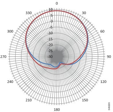
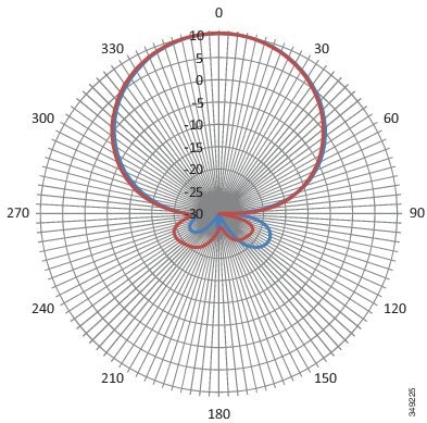
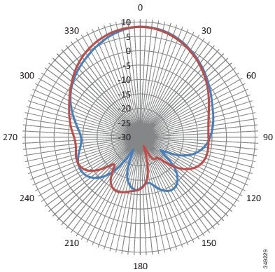
698 MHz Antenna Radiation Pattern—Horizontal Plane
Figure 6-2 698 MHz Antenna Radiation Pattern—Horizontal Plane
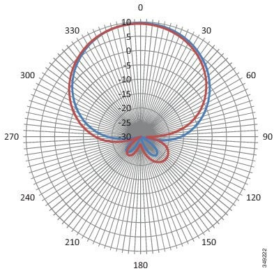
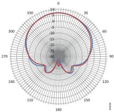
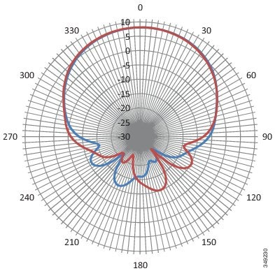
698 MHz Antenna Radiation Pattern—Vertical Plane
Figure 6-3 698 MHz Antenna Radiation Pattern—Vertical Plane

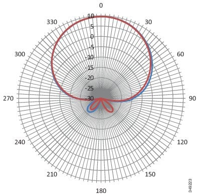
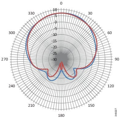
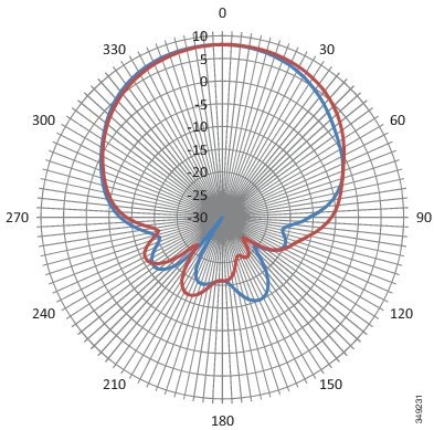
880MHz Antenna Radiation Pattern—Horizontal Plane
Figure 6-4 880 MHz Antenna Radiation Pattern—Horizontal Plane
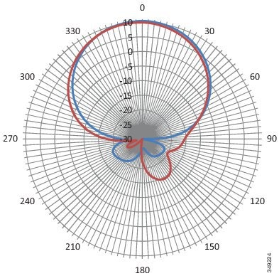
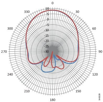
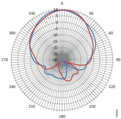
880MHz Antenna Radiation Pattern—Vertical Plane
Figure 6-5 880 MHz Antenna Radiation Pattern—Vertical Plane
960 MHz Antenna Radiation Pattern—Horizontal Plane
Figure 6-6 960 MHz Antenna Radiation Pattern—Horizontal Plane
960 MHz Antenna Radiation Pattern—Vertical Plane
Figure 6-7 960 MHz Antenna Radiation Pattern—Vertical Plane
1710 MHz Antenna Radiation Pattern—Horizontal Plane
Figure 6-8 1710 MHz Antenna Radiation Pattern—Horizontal Plane
1710 MHz Antenna Radiation Pattern—Vertical Plane
Figure 6-9 1710 MHz Antenna Radiation Pattern—Vertical Plane
1950 MHz Antenna Radiation Pattern—Horizontal Plane
Figure 6-10 1950 MHz Antenna Radiation Pattern—Horizontal Plane
1950 MHz Antenna Radiation Pattern—Vertical Plane
Figure 6-11 1950 MHz Antenna Radiation Pattern—Vertical Plane
2170 MHz Antenna Radiation Pattern—Horizontal Plane
Figure 6-12 2170 MHz Antenna Radiation Pattern—Horizontal Plane
2170 MHz Antenna Radiation Pattern—Vertical Plane
Figure 6-13 2170 MHz Antenna Radiation Pattern—Vertical Plane
2700 MHz Antenna Radiation Pattern—Horizontal Plane
Figure 6-14 2700 MHz Antenna Radiation Pattern—Horizontal Plane
2700 MHz Antenna Radiation Pattern—Vertical Plane
Figure 6-15 2700 MHz Antenna Radiation Pattern—Vertical Plane

Installing the Antenna
The antenna installation includes the following procedures:
- Contents of the Antenna Kit
- Safety Warnings
- Safety Precautions
- Tools and Equipment Required
- Preparing the Antenna for Installation
- Mounting the Antenna
- Connecting the Lightning Arrestor
- Connecting the Antenna to the Router
Safety Warnings

Warning Avoid using or servicing any equipment that has outdoor connections during an electrical storm.
There may be a risk of electric shock from lightning. Statement 1088
Warning Do not work on the system, or connect or disconnect cables, during periods of lightning activity. Statement 1001
Warning Do not locate the outdoor antenna near overhead power lines or other electric light or power circuits, or where it can come into contact with such circuits. When installing the antenna, take extreme care not to come into contact with such circuits, as they may cause serious injury or death. For proper installation and grounding of the antenna, please refer to national and local codes (for example, U.S.:NFPA 70, National Electrical Code, Article 810, Canada:Canadian Electrical Code, Section 54). Statement 1052
Warning This equipment must be grounded. Never defeat the ground conductor or operate the equipment in the absence of a suitably installed ground conductor. Contact the appropriate electrical inspection authority or an electrician if you are uncertain that suitable grounding is available. Statement 1024
Warning Only trained and qualified personnel should be allowed to install, replace, or service this equipment. Statement 1030
Warning To report a gas leak, do not use a telephone in the vicinity of the leak. Statement 1039
Warning This warning symbol means danger. You are in a situation that could cause bodily injury. Before you work on any equipment, be aware of the hazards involved with electrical circuitry and be familiar with standard practices for preventing accidents. Use the statement number provided at the end of each warning to locate its translation in the translated safety warnings that accompanied this device. Statement 1071. SAVE THESE INSTRUCTIONS.
Warning This product is not intended to be directly connected to the Cable Distribution System. Additional regulatory compliance and legal requirements may apply for direct connection to the Cable Distribution System. This product may connect to the Cable Distribution System ONLY through a device that is approved for direct connection. Statement 1078
Safety Precautions
Warning Installation of this antenna near power lines is dangerous. For your safety, follow the installation directions.
Each year hundreds of people are killed or injured when attempting to install an antenna. In many of these cases, the victim was aware of the danger of electrocution, but did not take adequate steps to avoid the hazard.
For your safety, and to help you achieve a good installation, please read and follow these safety precautions. They may save your life!
For your safety, read and follow these safety precautions.
- If you are installing an antenna for the first time, for your own safety as well as others, seek professional assistance. Your Cisco sales representative can explain which mounting method to use for the size and type antenna you are about to install.
- Before you install an antenna, contact your Cisco account representative to explain which mounting method to use for the size and type of antenna that you are about to install.
- Find someone to help you—installing an antenna is often a two-person job.
- Select your installation site with safety, as well as performance, in mind. Remember that electric power lines and phone lines look alike. For your safety, assume that any overhead line can kill you.
- Contact your electric power company. Tell them your plans and ask them to come look at your proposed installation.
- Plan your installation carefully and completely before you begin. Each person involved in an installation should be assigned to a specific task, and should know what to do and when to do it. One person should be in charge of the operation to issue instructions and watch for signs of trouble.
- When installing your antenna, follow these guidelines:
– Do not work on a wet or windy day.
– Do dress properly—wear shoes with rubber soles and heels, rubber gloves, and a long-sleeved shirt or jacket.
- If the assembly starts to drop, move away from it and let it fall. Because the antenna, mast, cable, and metal guy wires are all excellent conductors of electrical current, even the slightest touch of any of these parts to a power line completes an electrical path through the antenna and the installer.
- If any part of the antenna system should come in contact with a power line, do not touch it or try to remove it yourself. Call your local power company to have it removed safely.
- If an accident should occur with the power lines, call for qualified emergency help immediately.
Tools and Equipment Required
In addition to the parts included in the antenna kit described in the section Contents of the Antenna Kit, you must provide the following tool to install the antenna on the router:

Note This list does not include the tools and equipment required to assemble and erect the tower, mast, or other structure you intend to mount your antenna on.
Preparing the Antenna for Installation
Note Before mounting the antenna on a mast or wall:
- the antenna must be attached to the mounting bracket.
- the signal cable must be attached to the antenna.
To prepare the antenna for installation:
Step 1 Attach the antenna to the mounting bracket.
Step 2 To attach the signal cable to the antenna:
a. Loosely hand-tighten the antenna nut so that the cable can be attached with ease.
b. Attach the cable to the antenna.
c. Hand tighten the N-connector to the antenna.
d. Tighten the antenna nut securely after the cable is installed.
e. Use weatherproof sealing tape (coax seal) at the connector junction. Start wrapping at the top of the antenna connector, wrap downward 3 times and end about 2 inches downward from the center of the connector junction. Then wrap upwards another 3 times to reach the top of the antenna connector.
Step 3 Decide if the antenna is to be mounted on a wall or mast. Perform the following steps where relevant:
a. If the antenna is going to be mast mounted, install the clamps provided in the mounting bracket. Align the antenna so the top of the metal bracket is even with or slightly above the top of the mast tubing.
b. If the antenna is to be wall mounted, use the screws provided.
c. Use both clamps and screws for extra security if required.
Mounting the Antenna
Follow these instructions to mount the antenna:
Step 1 Mark the desired location where you plan to mount the antenna and create a hole to receive the antenna.
Note The rubber washer is not required for ceiling tile installations.
Step 2 Make sure that the antenna is properly positioned, then tighten the washer and plastic nut to secure the antenna.
Connecting the Lightning Arrestor
To install a lightning-protection device, seeCisco Lightning Arrestors in Chapter 1, “Cisco CGR 1000 and 2000 Series Connected Grid Antennas Overview”.
Connecting the Antenna to the Router
To attach the router-end of the cable to your router, see Connecting the Antenna to the CGR 1120 in Chapter 1, “Cisco CGR 1000 and 2000 Series Connected Grid Antennas Overview”.
Note Coaxial cable loses efficiency as the frequency increases, resulting in signal loss. The cable should be kept as short as possible because cable length also determines the amount of signal loss—the longer the cable length or run, the greater the loss).
Obtaining Documentation and Submitting a Service Request
For information on obtaining documentation, submitting a service request, and gathering additional information, see the monthly What’s New in Cisco Product Documentation, which also lists all new and revised Cisco technical documentation, at:
http://www.cisco.com/en/US/docs/general/whatsnew/whatsnew.html
Subscribe to the What’s New in Cisco Product Documentation as an RSS (Really Simple Syndication) feed, and set it so content is delivered directly to your desktop using a reader application. The RSS feeds are a free service and Cisco currently supports RSS Version 2.0.
 Feedback