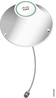
Cisco Multiband Indoor 4G Volcano Antenna (ANT-4G-CM-IN-TNC)
This document describes the Cisco Multiband Indoor 4G Ceiling-mount Volcano Antenna that is supported on the Cisco CGR 2010, 1240, and 1120 routers. It supports frequencies of 698 to 960 MHz, 1575 MHz, and 1710 to 2700 MHz for the GSM, DCS, UMTS, and LTE/WiMAX frequency bands. In addition, this document provides the antenna specifications and mounting instructions of the antenna.

Technical Specifications
The 4G Volcano Antenna features the following:
- Indoor ceiling mount
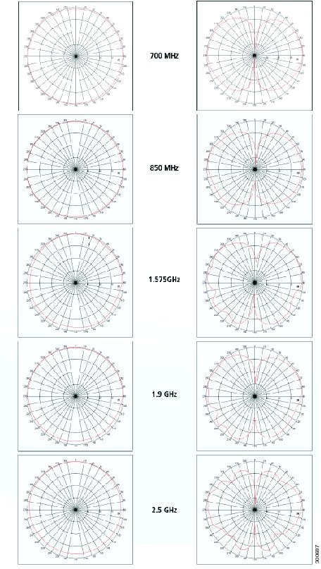
- Radiation pattern shaped to perform optimally for a ceiling-mount antenna
- Low-profile, aesthetically neutral housing
- Performance optimized using proprietary RF optimization tools
- Excellent flame rating
Contents of the Antenna Kit
The Cisco Multiband Indoor 4G Ceiling-mount Volcano Antenna Kit contains the following items:
Installation Requirements
Optimum Performance
Antennas transmit and receive radio signals which are susceptible to RF obstructions and common sources of interference that can reduce throughput and range of the device to which they are connected. Follow these guidelines to ensure the best possible performance:
- Keep the antenna away from metal obstructions such as heating and air-conditioning ducts, large ceiling trusses, building superstructures, and major power cabling runs. If necessary, use a rigid conduit to lower the antenna away from these obstructions.
- The density of the materials used in surrounding buildings’ construction impacts antenna signal strength. Consider the following
– Signals penetrate paper and vinyl walls with little change to signal strength.
– Signals penetrate only one or two solid and pre-cast concrete walls without degrading signal strength.
– Signals penetrate three or four concrete and wood block walls without degrading signal strength.
– Signals penetrate five or six walls constructed of drywall or wood without degrading signal strength.
– Signals are likely to reflect off a thick metal wall and not penetrate it at all.
– Signals are likely to reflect off a chain link fence or a wire mesh with spaces of 1 to 1-1/2 in. (2.5 to 3.8 cm). The fence acts as a harmonic reflector that blocks the signal.
- Microwave ovens and 2-GHz cordless phones can cause signal interference because they operate in the same frequency range as the device to which your antenna is connected.
- For instructions on installing or replacing a Cisco Connected Grid module, see the corresponding installation and configuration guide for each module.
- For detailed instructions on opening the door, see the installation guide of your router. Before installing the antenna according to the Installing the Antenna, you must complete these steps:
– Open the router chassis door.
– Remove any plug or connector that is installed in the antenna port.
– Verify the correct antenna port for installation, based on the antenna model you are installing.
- See the installation document for your router regarding the correct antenna port location. Antennas must be installed in the correct antenna port for ease of installation and optimal performance.

Note Ensure that you are able to access the antenna port from inside the router. If an installed module prevents you from reaching the antenna port, you might have to remove the module before installing the antenna, then reinstall the module. See the corresponding module installation and configuration guide for each module.
Safety Warnings

Warning Do not work on the system, or connect or disconnect cables, during periods of lightning activity. Statement 1001
Warning Do not locate the outdoor antenna near overhead power lines or other electric light or power circuits, or where it can come into contact with such circuits. When installing the antenna, take extreme care not to come into contact with such circuits, as they may cause serious injury or death. For proper installation and grounding of the antenna, please refer to national and local codes (for example, U.S.:NFPA 70, National Electrical Code, Article 810, Canada:Canadian Electrical Code, Section 54). Statement 1052
Warning This equipment must be grounded. Never defeat the ground conductor or operate the equipment in the absence of a suitably installed ground conductor. Contact the appropriate electrical inspection authority or an electrician if you are uncertain that suitable grounding is available. Statement 1024
Warning Only trained and qualified personnel should be allowed to install, replace, or service this equipment. Statement 1030
Warning To report a gas leak, do not use a telephone in the vicinity of the leak. Statement 1039
Warning This warning symbol means danger. You are in a situation that could cause bodily injury. Before you work on any equipment, be aware of the hazards involved with electrical circuitry and be familiar with standard practices for preventing accidents. Use the statement number provided at the end of each warning to locate its translation in the translated safety warnings that accompanied this device. Statement 1071. SAVE THESE INSTRUCTIONS.
Warning This product is not intended to be directly connected to the Cable Distribution System. Additional regulatory compliance and legal requirements may apply for direct connection to the Cable Distribution System. This product may connect to the Cable Distribution System ONLY through a device that is approved for direct connection. Statement 1078
Warning This warning symbol means danger. You are in a situation that could cause bodily injury. Before you work on any equipment, be aware of the hazards involved with electrical circuitry and be familiar with standard practices for preventing accidents.
Safety Precautions
For your safety, and to help you achieve a good installation, please read and follow these safety precautions. They may save your life!
For your safety, read and follow these safety precautions.
- If you are installing an antenna for the first time, for your own safety as well as others, seek professional assistance. Your Cisco sales representative can explain which mounting method to use for the size and type antenna you are about to install.
- Before you install an antenna, contact your Cisco account representative to explain which mounting method to use for the size and type of antenna that you are about to install.
- Find someone to help you—installing an antenna is often a two-person job.
- Plan your installation carefully and completely before you begin. Each person involved in an installation should be assigned to a specific task, and should know what to do and when to do it. One person should be in charge of the operation to issue instructions and watch for signs of trouble.
Antenna Installation
The antenna installation includes the following procedures:
Tools and Equipment Required
In addition to the parts included in the antenna kit described in the section Contents of the Antenna Kit, you must provide the following tool to install the antenna on the router:
Installing the Antenna
Follow these instructions to install the antenna:
Step 1 Determine where on the ceiling you want to install the antenna.
Step 2 Create the center hole to accommodate the 3/4”-16 threaded center rod on the Volcano antenna.
Step 3 Position the Volcano antenna onto the ceiling. Mark on the ceiling the location of the three holes.
Step 4 Remove the antenna and drill the three holes. Place the screw anchors into the holes.
Step 5 Position the antenna in place. Secure the antenna onto the ceiling with the 3 screws using a Phillips #2 screwdriver.
Step 6 From inside the ceiling space, place, in order, the flat washer and curved spring washer onto the center rod. Secure the antenna with the mounting nut.
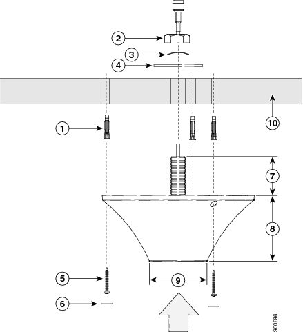
Step 7 Place the self-adhesive screw covers (3) over the screw holes on the antenna.
Step 8 Attach the cable to the antenna connector.
Step 9 Attach the router-end of the cable to your router. See Connecting the Antenna to the CGR 1120 in Chapter 1, “Cisco CGR 1000 and 2000 Series Connected Grid Antennas Overview”.
Obtaining Documentation and Submitting a Service Request
For information on obtaining documentation, submitting a service request, and gathering additional information, see the monthly What’s New in Cisco Product Documentation, which also lists all new and revised Cisco technical documentation, at:
http://www.cisco.com/en/US/docs/general/whatsnew/whatsnew.html
Subscribe to the What’s New in Cisco Product Documentation as an RSS (Really Simple Syndication) feed, and set it so content is delivered directly to your desktop using a reader application. The RSS feeds are a free service and Cisco currently supports RSS Version 2.0.
 Feedback