Feedback
Table Of Contents
24 Channelized T1/E1 Trunk Card
Verifying and Troubleshooting the Installation
Configuring the 24 Channelized T1/E1 Trunk Card
Using the Bantam Jacks for Test Port Functionality
24 Channelized T1/E1 Trunk Card
The Cisco AS5850 universal gateway supports channelized T1 (CT1) and E1 (CE1) ingress interfaces that provide a synchronous telecommunications interface in both North American and international environments. The 24 channelized T1/E1 trunk card supports 24 CT1 or CE1 connections, and the Cisco AS5850 can hold as many as two 24 channelized T1/E1 trunk cards per route switch controller (RSC).
This chapter describes card T1/E1 line functionality, connectors and LEDs, steps for verifying and troubleshooting your 24 channelized T1/E1 trunk card installation, and card specifications.
This chapter contains the following sections:
•
Configuring the 24 Channelized T1/E1 Trunk Card
•
Overview
The 24 channnelized T1/E1 trunk card has three T1/E1 interfaces and each interface supports eight T1/E1 PRI ports. Each 24 channelized T1/E1 trunk card can be installed in Cisco AS5850 server slots 0 to 5 or 8 to 13. The 24 channelized T1/E1 trunk card contains all necessary functionality to terminate as many as 576 DS0 channels in T1 mode and 720 DS0 channels in E1 mode and uses onboard High-Level Data Link Control (HDLC) controllers to terminate digital ISDN calls. You can use the Bantam jacks on the face of the card to monitor a line.
Note
Note
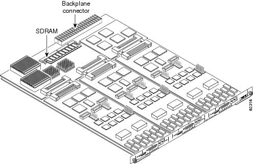
Figure 2-1 shows the 24 channelized T1/E1 trunk card components.
Figure 2-1 24 Channelized T1/E1 Trunk Card
The 24 channelized T1/E1 trunk card performs the following functions:
•
The 24 channelized T1/E1 trunk card provides physical termination for as many as twenty-four T1/E1 lines and connects to an external network termination (NT1) device.
•
A framer removes framing and embedded signaling bits (or inserts them, depending on the direction of the flow), and the framer CPU sends the data stream to onboard time-division multiplexing (TDM) resources, which break out each call (DS0) and pass each call to an appropriate call termination resource. Digital calls are terminated onboard the 24 channelized T1/E1 trunk card on HDLC controllers, and analog modem-originated calls are passed over the dial shelf backplane TDM bus to an available modem resource. The system software controls port and HDLC resource management.
•
Each individual T1/E1 connection can be used as the system clocking reference. Each 24 channelized T1/E1 trunk card can supply two clocks from any two of its 24 ports. You can assign priorities to these clocks or accept the default values assigned by the software.
•
•
The 24 channelized T1/E1 trunk card supports OIR, a feature that allows you to remove and replace trunk cards in the Cisco AS5850 while the system is operating, without disrupting other cards and their associated calls. If you remove a trunk card while the system is operating, all calls associated with the lines on that card are dropped. Calls being handled by other trunk or modem cards, however, are not affected. For more information, see the "Busyout Command" section on page 1-1.
The Cisco AS5850 supports a mixture of 24T1 and T3/216 trunk cards. Table 2-1 shows the possible trunk card configurations:
Note
Note
Clocking
All Cisco AS5850 trunk cards use the same transmit clock. This clock can originate from the following sources:
•
•
Clocks are prioritized by slot number. The highest-priority clock is selected from the card in slot 0 and is used as the default clock. If this clock fails, the highest-priority clock from the card in slot 1 becomes the default clock, and so forth.
The trunk card then forwards the clocks to the route switch controller. The route switch controller selects the highest-priority clock as the system primary clock, and the rest of the clocks remain in a prioritized backup queue.
Instead of using the default algorithm for clock selection, you can specify clocks through global configuration and select a maximum of two clocks per trunk card.
If you configure fewer than two clocks on a trunk card and all other configured clocks fail, clock selection resorts to the default algorithm on that card and the second clock is selected automatically.
LED Indicators
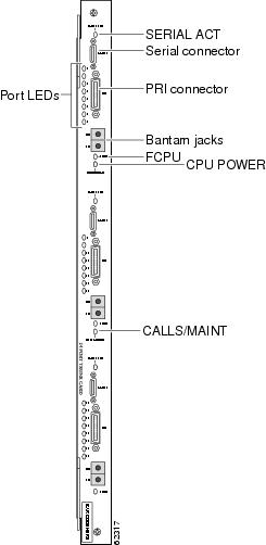
The 24 channelized T1/E1 trunk card front panels are designed with LED indicators (Figure 2-2) to provide trunk card status and port-level monitoring information.
Figure 2-2 24 Channelized T1/E1 Trunk Card LEDs
The two types of LEDs for the 24 channelized T1/E1 trunk cards are:
•
•
All LEDs are visible from the front panel. (See Figure 2-2.)
Table 2-2 lists the 24 T1/E1 trunk card LEDs and their functions.
Table 2-2 24 channnelized T1/E1 trunk card LED Indicators
SERIAL ACT
Off
The serial connector is not available.
Port LEDs
Yellow
Port-associated LEDs providing indication of local alarm, remote alarm, or loopback detected on the corresponding PRI line.
FCPU
Green
Framing data link (FDL)—Stays blinking when the associated FDL CPU is determined to be in good working condition; goes off or stays on when an error condition is found.
CPU/POWER
Green
24 channelized T1/E1 trunk card passed diagnostics, and the card CPU is operating properly.
Yellow
Comes on shortly after the card is powered on.1 Card CPU diagnostics start when the card starts receiving power, and the LED remains yellow while the diagnostics run.
Off
Card not receiving power.
CALLS/MAINT
Green
The LED comes on when at least one active call is switched through the card's port handling circuits.
Yellow
Indicates card OIR status. The LED is yellow when the card has been busied out and has no calls, and may be removed without interrupting service.
Off
The CALLS/MAINT LED is not on if there is no traffic on the card and the card has not been busied out.
1 There is a slight delay from the time that power is applied to the card to the time that this LED comes on.
Specifications
Table 2-3 lists the 24 T1/E1 trunk card specifications.
Table 2-3 24 T1/E1 Trunk Card Specifications
Dimensions H x W x L
15.4 x 0.08 x 18.7 in. (39.12 x 0.203 x 47.5 cm) without the carrier
15.5 x 1.23 x 19 in. (39.37 x 3.12 x 48.26 cm) with the carrierWeight
8 lb (3.6 kg)
Transmission bit rate
1.544 Mbps (T1 mode), 2.048 Mbps (E1 mode)
Power requirements
-48 VDC at 2 A (power consumption: 3.3 VDC and 5 VDC)
Regulatory compliance and safety1
CTR4, CTR12, CTR13, ACA TS001, TS016, EN60950, IEC60950, and AS3260
1 See also the regulatory compliance and safety document that shipped with your Cisco AS5850.
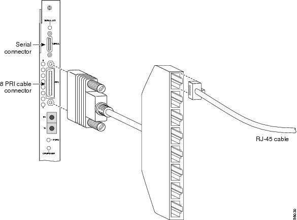
Connecting Trunk Card Cables
The 24 T1/E1 trunk cards provide a PRI port requiring an adaptor to accept as many as eight RJ-45 receptacles for T1 or E1 lines. To connect T1 or E1 lines, follow these steps:
Warning
Step 1
Step 2
Warning
Warning
Figure 2-3 24 T1/E1 Trunk Card RJ-45 Cable Connections
Step 3
Note
Warning
Verifying and Troubleshooting the Installation
When you first power on your Cisco AS5850 universal gateway, all LEDs go on while the system runs a series of diagnostics. After the system passes initial diagnostics, all LEDs go off. The LEDs then go on again as described in Table 2-4.
To complete the installation, verify that the trunk card LEDs operate properly by observing the LED states.
Table 2-4 24 Channelized T1/E1 Trunk Card LED Indicators
SERIAL ACT
Off
The serial connector is not available.
Port LEDs
Yellow
Port-associated LEDs providing indication of local alarm, remote alarm, or loopback detected on the corresponding Primary Rate Interface (PRI) line.
FCPU
Green
Framing data link (FDL)—Stays blinking when the associated FDL CPU is determined to be in good working condition; goes off or stays on when an error condition is found.
CPU/POWER
Green
24 channelized T1/E1 trunk card passed diagnostics, and the card CPU is operating properly.
Yellow
Goes on shortly after the card is powered on.1 Card CPU diagnostics start when the card starts receiving power, and the LED remains yellow while the diagnostics run.
Off
Card not receiving power.
CALLS/MAINT
Green
The LED goes on when at least one active call is switched through the card's port handling circuits.
Yellow
Indicates card OIR status. The LED is yellow when the card has been busied out and has no calls, and may be removed without interrupting service.
Off
The CALLS/MAINT LED does not go on if there is no traffic on the card and the card has not been busied out.
1 There is a slight delay from the time that power is applied to the card to the time that this LED goes on.
•
If the FCPU LED is off, or continually on, wait while the auto-reload feature on the server card attempts to reload the trunk firmware. If the software fails to reload after the programmed number of times, assume that the failure is due to defective hardware. Return the card to the factory for replacement.
•
If the CPU/POWER LED remains off, verify that the card is seated properly.
If the CPU/POWER LED is yellow, diagnostics are still running on the 24 channelized T1/E1 trunk card. If the CPU/POWER LED stays yellow, contact TAC. To contact Cisco's Technical Assistance Center (TAC) refer to the "Obtaining Documentation" section on page xvi.
If the power LED comes on for other 24 channelized T1/E1 trunk cards in the server, try inserting the 24 channelized T1/E1 trunk card in a different slot. If none of the power LEDs come on, check your dial shelf power connections, power entry modules, and AC-input power supplies (if present).
•
If the CALLS/MAINT LED is off but the power LED is on, there is no traffic on the card.
Verify that the other cards in the server work properly. Verify that the card is seated properly. Try inserting the card in a different slot.
Tip
Configuring the 24 Channelized T1/E1 Trunk Card
Note
Basic Configuration
This section shows how to configure channelized T1 or E1. You can allocate the available channels for channelized E1 and T1 in the following ways:
•
•
•
•
•
Note
The following steps will configure a basic T1 or E1 controller:
Step 1
Gateway> enablePassword: passwordGateway#Step 2
Gateway# configure terminalEnter configuration commands, one per line. End with CNTL/Z.Gateway(config)#Step 3
Gateway(config)# controller [t1 | e1] slot/portGateway(config-controller)#Step 4
Gateway(config-controller)# framing esfor
Enter the framing type for the CE1 controller.
Gateway(config-controller)# framing crc4Step 5
Gateway(config-controller)# linecode b8zsor
Define the line code as high-density bipolar 3 (HDB3) for the CE1 controller.Gateway(config-controller)# linecode hdb3Step 6
Gateway(config-controller)# Ctrl-ZGateway#
Tip
Verify
To verify that your controller is up and running and no alarms have been reported:
•
Gateway# show controller t1 1/7T1 1/7 is up.No alarms detected.Framing is ESF, Line Code is B8ZS, Clock Source is Line Primary.Version info of slot 2: HW: 2, Firmware: 14, NEAT PLD: 13, NR Bus PLD: 19Data in current interval (476 seconds elapsed):0 Line Code Violations, 0 Path Code Violations0 Slip Secs, 0 Fr Loss Secs, 0 Line Err Secs, 0 Degraded Mins0 Errored Secs, 0 Bursty Err Secs, 0 Severely Err Secs, 0 Unavail SecsTotal Data (last 24 hours)0 Line Code Violations, 0 Path Code Violations,0 Slip Secs, 0 Fr Loss Secs, 0 Line Err Secs, 0 Degraded Mins,0 Errored Secs, 0 Bursty Err Secs, 0 Severely Err Secs, 0 Unavail Secs•
–
–
If you are having trouble:
•
•
•
Configuring Input Impedance
Use the line-termination command to set the input impedance for the 24 channelized T1/E1 trunk card. Configure input impedance by using the following steps.
Step 1
Gateway> enablePassword: passwordGateway#Step 2
Gateway# configure terminalEnter configuration commands, one per line. End with CNTL/Z.Gateway(config)#
Step 3
Gateway(config)# controller e1 0/0Gateway(config-controller)#Step 4
Gateway(config-controller)# line-termination 75-ohmStep 5
Gateway(config-controller)# Ctrl-ZGateway#
Verifying Impedance
To verify your impedance, enter the show running-config command. Note that 120 ohms is the default value and is not displayed in the configuration file. The following output is an abbreviated example of the relevant output after having entered the command line-termination 75-ohm for controller E1 0.
Gateway# show running-configBuilding configuration...Current configuration:!..controller E1 0/0clock source free-runningline-termination 75-ohmpri-group timeslots 1-31!controller E1 1/0clock source line secondary 1pri-group timeslots 1-31...endGateway#Using the Bantam Jacks for Test Port Functionality
Test port functionality is supported by Cisco IOS Release 12.1(2)XD and later releases.
Note
Monitor Mode
The monitor mode is available on the 24 channelized T1/E1 trunk card and channelized T3 trunk cards.
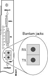
If a controller does not go up, or there are a large number of errors associated with a specific controller, you might be able to determine whether the problem is in the server card or in an external line by using the test port. The three test ports are located on the front panel of the 24 channelized T1/E1 trunk card. Each test port is a set of Bantam jack connectors directly beneath the 8-port T1/E1 interface connector.
The Bantam jack connectors allow the connection of an external test device (for example, a FIREBERD test device) to monitor an individual circuit in monitor mode. (See Figure 2-4.)
Note
Use the test trunk monitor command to enable and disable passive monitoring on a specific T1/E1 controller:
Gateway# test trunk monitor on 3/2
Gateway# test trunk monitor off 3/2
Use the show trunk testport command to check which ports are being monitored:
Gateway# show trunk testport
For more information on software commands, see the Cisco AS5850 Operations, Administration, Maintenance, and Provisioning Guide, available online at http://www.cisco.com/univercd/cc/td/doc/product/access/acs_serv/as5850/sw_conf/5850oamp/ index.htm.
Passive monitoring equipment is used to listen on the TX MON and RX MON jacks during regular operation to detect errors.
Connecting test equipment to the following Bantam jack connectors provides various functions:
•
•
Figure 2-4 24 T1/E1 Trunk Card Bantam Jacks
Warning