Feedback
Table Of Contents
324 Universal Port Card Overview
Verifying and Troubleshooting the Installation
Universal Port Cards
The Cisco AS5850 universal gateway is equipped with dedicated universal port (324 universal port) cards, dedicated trunk (24T1/E1) cards, and mixed-use trunk and port handling services (T3/216 universal port) cards. This chapter provides an overview of the 324 universal port card (UPC), which supports modem services, and includes steps for configuring your software and verifying and troubleshooting your UPC installation.
The universal port handling capabilities of the channelized T3 cards function identically to ports handled on the UPC, the only difference being the number of ports handled.
This chapter describes the functionality of the universal port card and includes steps for verifying and troubleshooting.
This chapter contains the following sections:
•
324 Universal Port Card Overview
324 Universal Port Card Overview
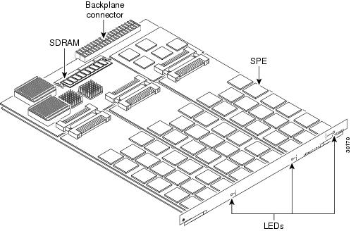
A universal port is a port that can carry the equivalent of one DS0 of network traffic. Network traffic can be a modem, voice, or fax connection. The core hardware components are service processing elements (SPEs), each of which support six universal ports. There are 54 SPEs per UPC, for a total of 324 ports per UPC. Each UPC also has a minimum of one 64-megabyte SDRAM card. Configuration, management, and troubleshooting of universal ports can be done at the UPC, SPE, and port level.
Currently the UPC supports data, voice, and fax traffic and is universal port capable, depending on the software and platform. Each UPC plugs directly into the server backplane and has no external connections. Each UPC has three LEDs that indicate card status.
Figure 5-1 shows the UPC components.
Figure 5-1 324 Universal Port Card Components
The UPC performs the following functions:
•
•
•
•
A UPC can be installed in slots numbered 0 through 5 or 8 through 13 on the server backplane.
LED Indicators
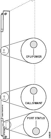
The UPC has three LEDs (see Figure 5-2) to indicate card status. The these LEDs can be green, yellow, or off.
Figure 5-2 324 Universal Port Card LEDs
During normal operation, all three LEDs light as described in Table 5-1.
Table 5-1 UPC LED Descriptions
CPU/POWER
Green
UPC passed diagnostics and the card CPU is operating properly.
Yellow
Goes on shortly after the card is powered on.1 Card CPU diagnostics start when the card starts receiving power, and the LED remains yellow while the diagnostics run.
OFF
UPC not receiving power, or portware failed to load. If the portware fails to load onto the card, the Cisco AS5850 attempts to reload the portware automatically. If a programmed number of attempts to reload the portware fails, the Cisco AS5850 powers off the UPC.
CALLS/MAINT
Green
The LED goes on when at least one active call is switched through the card.
Yellow
Indicates card OIR status. The LED is yellow when the card has been busied out and has no calls, and may be removed without interrupting service.
OFF
The CALLS/MAINT LED is not lit if there is no traffic on the card, and the card has not been busied out.
PORT STATUS
Green
Goes on when all SPE modules have passed diagnostics and are operating properly.
OFF
LED remains off until diagnostics are complete. If this LED stays off, one or more SPE modules are missing from the card or one or more SPEs failed diagnostics.
1 There is a slight delay from the time that power is applied to the card to the time that this LED goes on.
Startup Sequence
1.
2.
3.
4.
5.
6.
SPE Firmware
SPE firmware is automatically downloaded to a UPC from the server's Cisco IOS image when you boot the system for the first time or when you insert a UPC while the system is operating. When you insert a UPC while the system is operating, the Cisco IOS image recognizes the card and the server downloads the required portware to the cards.
The SPE firmware image (also known as portware) is bundled with the Cisco IOS UPC image. The SPE firmware image uses an auto-detect mechanism, which enables the UPC to service multiple call types. An SPE detects the call type and automatically configures itself for that operation. You can upgrade the firmware without upgrading Cisco IOS software, and different firmware versions can be configured to run on SPEs in the same UPC.
If a problem develops requiring a reload of SPE firmware to an SPE, busyout traffic on the SPE's active ports before reloading. Reloading firmware for an SPE affects all ports handled by the SPE, and any connections handled by a port on the SPE during a reload will be dropped.
The UPC supports the features listed in Table 5-2.
Verifying and Troubleshooting the Installation
The UPC's LEDs do not function without the proper Cisco IOS image running on the server. If you need to upgrade your Cisco IOS image, refer to the Cisco AS5850 Operations, Administration, Maintenance, and Provisioning Guide, available online at: http://www.cisco.com/univercd/cc/td/doc/product/access/acs_serv/as5850/sw_conf/5850oamp/ index.htm
During normal operation, all three UPC LEDs come on when the UPC is powered on. When the UPC CPU software starts running, it shuts off all LEDs except the power LED. The LEDs then come on again as described in Table 5-1.
To complete the installation, verify that the UPC LEDs operate properly by observing the following LED states:
•
If the CPU/POWER LED remains off, verify that the card is seated properly.
Note
If the CPU/POWER LED is yellow, diagnostics are still running on the UPC. If the CPU/POWER LED stays yellow, contact TAC. To contact the Cisco Technical Assistance Center (TAC) refer to the "Obtaining Documentation" section on page xvi.
If the power LED for other UPCs in the server comes on, try inserting the UPC in a different slot. If none of the power LEDs come on, check your server power connections, power entry modules, and AC-input power supplies (if present).
•
If the CALLS/MAINT LED is off but the power LED is on, there is no traffic on the card.
Verify that the other cards in the server work properly. Verify that the card is seated properly. Try inserting the card in a different slot. Verify that you are using the correct portware by using the show spe version command.
•
If the PORT STATUS LED is green, all SPEs present on the card passed diagnostics. You may also verify SPE operation by using the show spe command.
If the PORT STATUS LED is off, one or more SPEs present on the card failed diagnostics.
If troubleshooting reveals problems with the UPC, arrange to replace the UPC. To contact the Cisco Technical Assistance Center (TAC) refer to the "Obtaining Documentation" section on page xvi.
show spe command
To verify proper function of a UPC in a Cisco AS5850, you must use the show spe command and its variants described in the Cisco AS5850 Operations, Administration, Maintenance, and Provisioning Guide, available online at: http://www.cisco.com/univercd/cc/td/doc/product/access/acs_serv/as5850/sw_conf/5850oamp/ index.htm
For further installation troubleshooting information, refer to the Cisco AS5850 Universal Gateway Hardware Installation Guide.
Configuring the Ports
If you are replacing a server card with a new server card of the same type in the same slot, the system software recognizes the new server card interfaces and brings them up automatically. No additional configuration is needed.
You must insert the UPC in the desired slot as described in Chapter 1, "Replacing or Installing Server Cards."
Use the following commands to help you configure your UPC for basic dialup service.
Tip
If you are installing a new UPC into the server, no additional configuration is needed. For additional system software configuration information, refer to the Cisco AS5850 Operations, Administration, Maintenance, and Provisioning Guide, available online at: http://www.cisco.com/univercd/cc/td/doc/product/access/acs_serv/as5850/sw_conf/5850oamp/ index.htm
For More Information
For further information useful in troubleshooting or managing the UPC, refer to the Cisco AS5850 Operations, Administration, Maintenance, and Provisioning Guide, available online at: http://www.cisco.com/univercd/cc/td/doc/product/access/acs_serv/as5850/sw_conf/5850oamp/ index.htm