Feedback
Table Of Contents
Channelized T1 or E1 Trunk Card
CT1 and CE1 Trunk Card Overview
CT1 and CE1 Trunk Card Port Monitoring
CT1 and CE1 Trunk Card Port Pinout
CT1 Trunk Card Cables and Pinouts
CE1 Trunk Card Cables and Pinouts
Verifying and Troubleshooting the Installation
Configuring the CT1 and CE1 Trunk Card
Channelized T1 or E1 Trunk Card
The Cisco AS5800 universal access server supports channelized T1 (CT1) and channelized E1 (CE1) ingress interfaces that provide a synchronous telecommunications interface in both North American and international environments. The CT1/CE1 trunk card is installed in the Cisco 5814 dial shelf in the Cisco AS5800.
This chapter describes the , and it also includes steps for verifying and troubleshooting your CT1/CE1 trunk card installation.
CT1 and CE1 Trunk Card Overview
Channelized T1 or E1 ingress interfaces reside on CT1/CE1 trunk cards that are installed in the Cisco 5814 dial shelf. A CT1/CE1 trunk card contains all necessary functionality to terminate incoming telephone calls. The channelized trunk card is configured in the factory for either T1 or E1 framing, depending on your order.
Figure 2-1 shows the CT1 and CE1 trunk card components.
Figure 2-1 CT1 and CE1 Trunk Card
The CT1 and CE1 trunk cards perform the following functions:
•
Terminate as many as 12 T1 or 12 E1 lines
The CT1 trunk card provides physical termination for as many as 12 T1/Primary Rate Interface (PRI) lines, includes channel service units (CSUs), and connects directly to the telco network. The CE1 trunk card provides physical termination for as many as 12 E1 lines and connects to an external network termination (NT1) device.
•
A framer removes framing and embedded signaling bits (or inserts them, depending on the direction of the flow), and the framer CPU sends the data stream to onboard time-division multiplexing (TDM) resources, which break out each call (DS0) and pass each call to an appropriate call termination resource. Digital or ISDN-originated calls are terminated onboard the CT1/CE1 trunk card on High-Level Data Link Control (HDLC) controllers, and analog modem-originated calls are passed over the dial shelf backplane TDM bus to an available modem resource. The system software controls modem and HDLC resource management.
•
Each T1 or E1 port can be used as the system clocking reference. Each CT1/CE1 trunk card can supply two clocks from any two of its 12 ports. You can assign priorities to these clocks or accept the default values assigned by the software.
•
•
The CT1/CE1 trunk card supports OIR, a feature that allows you to remove and replace trunk cards in the Cisco 5814 dial shelf while the system is operating, without disrupting other cards and their associated calls. If you remove a trunk card while the system is operating, all calls associated with the lines on that card are dropped. Calls being handled by other trunk or modem cards, however, are not affected. For more information, see the "Busyout Command" section.
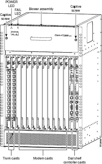
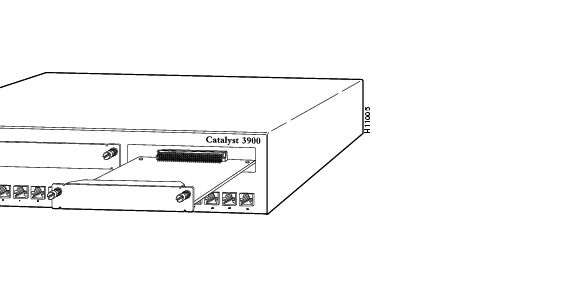
Figure 2-2 shows two CT1/CE1 trunk cards installed in a fully-configured Cisco 5814 dial shelf chassis.
Figure 2-2 Cisco 5814 Dial Shelf Chassis Fully Configured with Cards Installed
Clocking
All Cisco AS5800 access server trunk cards use the same transmit clock. This clock can originate from the following sources:
•
•
Clocks are prioritized by slot number (slots 0 to 5). The highest-priority clock is selected from the card in slot 0 and used as the default clock. If this clock fails, the highest-priority clock from the card in slot 1 becomes the default clock, and so forth.
The trunk card then forwards the clocks to the dial shelf controller. The dial shelf controller selects the highest-priority clock as the system primary clock, and the rest of the clocks remain in a prioritized backup queue.
Instead of using the default algorithm for clock selection, you can specify clocks through global configuration and select a maximum of two clocks per trunk card.
If you configure fewer than two clocks on a trunk card and all other configured clocks fail, clock selection resorts to the default algorithm on that card and the second clock will be selected automatically.
LED and LCD Indicators
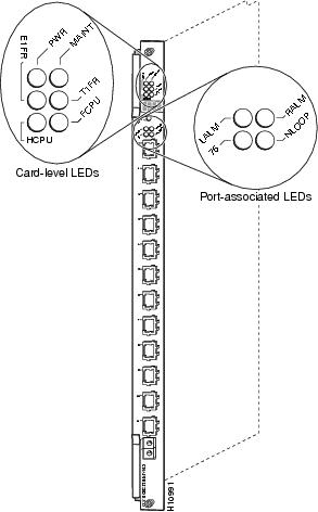
The CT1 and CE1 trunk card front panels are designed with LED indicators (Figure 2-3) and a liquid crystal display (LCD) (See Figure 2-4) to provide trunk card status and port-level monitoring information.
Figure 2-3 CT1 and CE1 Trunk Card Front Panel LEDs
There are two types of LEDs for the T1 and E1 trunk cards:
•
•
All LEDs are visible from the front panel. (See Figure 2-3.)
Table 2-1 lists the CT1 and CE1 trunk card LEDs and their functions.
CT1 and CE1 Trunk Card Port Monitoring
The CT1 and CE1 trunk card front panels are designed with an LCD to provide trunk card status and port-level monitoring information. (See Figure 2-4.) The current port number displayed in the LCD corresponds to the four port-associated LEDs.
Table 2-2 describes the port-associated LEDs and their functions.
Table 2-2 CT1 and CE1 Trunk Card Port-Associated LEDs
LALM
Yellow
Local alarm—Lights when an alarm condition is detected on incoming data.
RALM
Yellow
Remote alarm—Lights when the associated E1 port has detected loss of signal (LOS) or out-of-frame (OOF) errors. This occurs when the remote LIU1 receives errors and sends a signal to indicate the presence of remote errors.
75
Green
Ohm—E1 trunk card only. ON indicates 75 ohms, and OFF indicates 120 ohms.
NLOOP
Yellow
Network loopback—Lights when the port is configured in network loopback. This is useful for testing purposes.
1 LIU = line interface unit (analog physical interface). Refers to circuitry that interfaces a serial communications circuit to a transmission medium such as coaxial cabling.
Trunk Card Bantam Jacks
Passive port monitoring is supported through two shared bantam jacks located at the bottom of the trunk card front panel. (See Figure 2-4.) The bantam jacks allow you to connect a network monitoring device to the trunk card to detect T1 or E1 errors.
The four-character LCD indicates which line is to be monitored or inspected using the bantam jacks.
To enable the bantam jacks for port monitoring, follow these steps:
Step 1
You must release the button within 2 seconds to advance through the port numbers (from 0 to 11). After port 11, the display returns to port 0. As you advance through the port numbers, the LEDs reflect configuration status and alarm conditions for the port number displayed in the LCD.
Step 2
When you release the button, the port LCD no longer toggles through the port numbers, the letter "B" is displayed in the LCD, and the bantam jacks are enabled.
Step 3
Figure 2-4 CT1 and CE1 Trunk Card Front Panel LCD and Bantam Jacks
Specifications
Table 2-3 lists the CT1 and CE1 trunk card specifications.
Table 2-3 CT1 and CE1 Trunk Card Specifications
Dimensions H x W x L
15.4 x 0.08 x 18.7 in. (39.12 x 0.203 x 47.5 cm) without the carrier
15.5 x 1.23 x 19 in. (39.37 x 3.12 x 48.26 cm) with the carrierWeight
8 lb (3.6 kg)
T1
E11.544 Mbps
2.048 MbpsPower requirements
48 VDC (power consumption: 3.3 VDC and 5 VDC)
T1
E1AT&T Accunet TR 62411 specifications; JATE2 T98-6304-0; Pan-Euro CE-0168-X
ACA TS001, A53260; JATE N98-N019-0; Sweden 98031130; Singapore ISDN2-IPTA-AE 0345-98; Singapore DLCN1-MBPS-AO-0344-98; UK 607122
1 See also the regulatory compliance and safety document that shipped with your Cisco AS5800.
2 JATE = Japan Approval Telecommunication Equipment.
CT1 and CE1 Trunk Card Port Pinout
The CT1 trunk card receives and transmits 1.544-Mbps signals through a 100-ohm cable, using common RJ-45 connectors. Use a straight-through RJ-45 to RJ-45 cable to connect the T1 lines to an RJ-45 receptacle.
The CE1 trunk card receives and transmits 2.048-Mbps CE1 signals through either 120-ohm or 75-ohm coaxial cable. All CE1 interface cables use common RJ-45 connectors on the dial shelf end.
The receive impedance is software configurable as 75 ohms or 120 ohms. The T1 default value is 100 ohms. The E1 default value is 120 ohms. Use the line termination command in controller configuration mode to configure the receive impedance.
Table 2-4 lists the CT1 and CE1 port pinouts.
Table 2-4 CT1 and CE1 Trunk Card Port (RJ-45) Pinouts
1
Receive tip
2
Receive ring
3
Jumpered ground
4
Transmit tip
5
Transmit ring
6
Jumpered ground
7
Not used
8
Not used
Warning
CT1 Trunk Card Cables and Pinouts
One interface cable is available from Cisco Systems for connecting the CT1 card ports. The cable is described in Table 2-5.
Table 2-5 CT1 Interface Cable
RJ-45 to bare wire, 100-ohm
CAB-T1-RJ45BARE
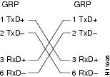
Figure 2-5 shows the CT1 interface cable, and Table 2-6 describes the pinouts for the CT1 interface cable.
Figure 2-5 RJ-45 to Bare Wire Interface Cable
CE1 Trunk Card Cables and Pinouts
Seven interface cables are available from Cisco Systems for connecting the CE1 card ports. These cables and their product numbers are listed in Table 2-7, along with the number of the figure and table detailing their pinouts.
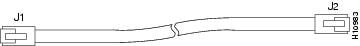
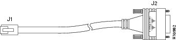
Figure 2-6 RJ-45 to RJ-45 Interface Cable
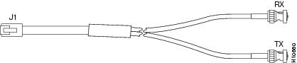
Figure 2-7 RJ-45-to-DB-15 Interface Cable
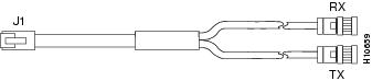
Figure 2-8 RJ-45 to BNC Interface Cable for 75-Ohm (Unbalanced Connections)
Figure 2-9 RJ-45 to Twinax Interface Cable for 75-Ohm (Unbalanced Connections)
Figure 2-10 RJ-45 to RJ-45 Interface Cable
Warning
Connecting Trunk Card Cables
The CT1 and CE1 trunk cards provide 12 RJ-45 receptacles for T1 or E1 lines. To connect T1or E1 lines, follow these steps:
Step 1
Step 2
Step 3
Warning
Figure 2-11 CT1 and CE1 Trunk Card RJ-45 Cable Connections
Warning
Configuring Cable Length
When you configure your CT1 trunk cards, you must include the length of the cable connected to the card. To specify this length, use the cablelength command. No cablelength command is required for CE1 trunk cards.
If you change the cable length when installing and cabling a new trunk card, you need to specify cable length in your software configuration. The cablelength command is designed to recognize two settings:
Cable Length Short
Cable length short defines the length of the cable (in feet) between your network access server (NAS) and your repeater. The cablelength short command includes the following settings:
•
•
•
•
•
Note
Cable Length Long
Cable length long defines the length range between your NAS and your repeater in gain and pulse. The cablelength long command includes the following gain and pulse settings:
•
•
•
•
•
•
To configure cable length, you must be in global configuration mode. Table 2-15 lists commands to help you configure your CT1 lines using the cablelength command.
Note
This completes the trunk card installation procedure. To verify the installation, proceed to the following section, "Verifying and Troubleshooting the Installation."
Verifying and Troubleshooting the Installation
When you first power ON your Cisco AS5800 access server, all LEDs light while the system runs a series of diagnostics. After the system passes initial diagnostics, all LEDs go off. The LEDs then light again as described in Table 2-1.
To complete the installation, verify that the trunk card LEDs operate properly by observing the following LED states:
•
If the power LED remains OFF, verify that the card is seated properly.
If the power LED lights on other trunk cards in the dial shelf, try inserting the trunk card in a different slot. If none of the power LEDs lights, check your dial shelf power connections, power entry modules, and AC-input power supplies (if present).
•
If the HCPU LED is OFF but the power LED is ON, the software image might have failed to load onto the card. The dial shelf controller attempts to reload the software automatically. After a programmed number of attempts to reload the software image fails, the dial shelf controller powers OFF the trunk card and all LEDs shut off.
If this happens, assume that the failure is due to defective hardware. Return the card to the factory for replacement. For information on how to contact Cisco, see the "Obtaining Documentation" section.
•
If the FCPU LED is OFF while the HCPU LED is ON, either the hardware is defective or the framer processor software has crashed. To determine if the failure is software related, wait while the auto-reload feature on the dial shelf controller card attempts to reload the software image. If the software fails to reload after the programmed number of times, assume that the failure is due to defective hardware. Return the card to the factory for replacement.
Tips
Configuring the CT1 and CE1 Trunk Card
The Cisco 5814 dial shelf recognizes CT1 and CE1 trunk cards only in slots 0 to 5 within the dial shelf chassis. Therefore, install trunk cards only in one of the first six slots.
If you are replacing a dial shelf card by installing a new dial shelf card of the same type in the same slot, the system software recognizes the new dial shelf card interfaces and brings them up automatically. No additional configuration is needed.
If you are installing a trunk card in a different slot than the trunk card that you just removed, additional configuration is needed. Refer to the Cisco AS5800 Universal Access Server Operation, Administration, Maintenance, and Provisioning Guide to configure the CT1 and CE1 interfaces.