Feedback
Table Of Contents
Verifying and Troubleshooting the Installation
Double-Density Modem Card
The Cisco AS5800 universal access server uses the Cisco Modem ISDN Channel Aggregation (MICA) double-density modem module cards (DMMs) to convert analog pulse-code modulation (PCM) bitstreams to digital data.
This chapter discusses the use of the double-density modem card in the Cisco 5814 dial shelf, the LEDs on the front of the card, the firmware that is used, and also includes steps for configuring your software and verifying and troubleshooting your DMM installation.
CT1/CE1 Trunk Card Overview
The Cisco AS5800 accommodates a maximum of ten CT1/CE1 trunk cards that use Cisco's MICA technology with upgradable firmware. Each CT1/CE1 trunk card plugs directly into the dial shelf backplane and has no external connections. Each CT1/CE1 trunk card has five LEDs, which indicate modem card status.
The Cisco AS5800 is capable of terminating as many as 1,344 modem connections when equipped with ten CT1/CE1 trunk cards and two CT3 trunk cards.
Each double-density modem card contains 12 DMM SIMMS. Each DMM SIMM contains 12 digital modems.
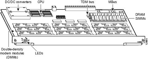
Figure 4-1 shows the double-density modem card components.
Figure 4-1 Double-Density Modem Card Components
The double-density modem card performs the following functions:
•
Converts PCM bitstreams to digital data.
DMMs perform the modulation and demodulation of the analog bitstreams. Each DMM comprises 12 digital modems. There are 12 DMMs on each DMM modem card; thus, each card can support a maximum of 144 modems.
•
•
•
CT1/CE1 trunk cards can be installed in slots numbered 0 to 11 on the dial shelf backplane. However, we recommend that you install modem cards in dial shelf slots 2 to 11 and reserve slots 0 and 1 for trunk cards. (Trunk cards are required for call termination and can only operate in slots 0 to 5.)
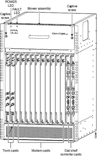
Figure 4-2 shows a fully-configured Cisco 5814 dial shelf with ten modem cards installed.
Figure 4-2 Cisco 5814 Dial Shelf with CT1/CE1 Trunk Cards Installed
LED Indicators
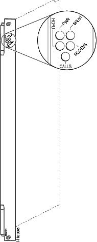
The DMM card has five LEDs to indicate modem card status. See Figure 4-3.
Figure 4-3 Double-Density Modem Card Front Panel LEDs
During normal operation, all five LEDs light when the system is powered ON and the CT1/CE1 trunk cards are ready. When the modem card CPU software image starts running, it shuts off all LEDs except the power LED. CT1/CE1 trunk card LEDs are listed in Table 4-1.
Modem Firmware
Modem card software is automatically downloaded to a modem card from the router shelf when you boot the system for the first time, or when you insert a modem card while the system is operating. If you insert modem cards while the system is operating, the system software recognizes the cards and the router shelf downloads the required portware to the cards.
The modem firmware image (also known as portware) is bundled with the Cisco IOS modem card image. The firmware image uses an auto-detect mechanism, which enables the modem to service multiple modem call types. A modem detects the call type and automatically configures itself for that operation.
The DMM modems can be programmed to collect ANI (calling number) and DNIS (called number) digits for caller identification information when the trunk cards are configured in channel-associated signaling (CAS) mode. The modem passes the ANI/DNIS information to the DMM card software using a portware mailbox message.
The CT1/CE1 trunk cards support the modem standards and features listed in Table 4-2.
Verifying and Troubleshooting the Installation
During normal operation, all five CT1/CE1 trunk card LEDs light when the modem card is powered ON. When the modem card CPU software starts running, it shuts off all LEDs except the power LED. The LEDs then light again as described in Table 4-1.
To complete the installation, verify that the CT1/CE1 trunk card LEDs operate properly by observing the following LED states:
•
If the power LED remains OFF, verify that the card is seated properly.
If the power LED lights on other modem cards in the dial shelf, try inserting the CT1/CE1 trunk card in a different slot. If none of the power LEDs light, check your dial shelf power connections, power entry modules, and AC-input power supplies (if present).
•
If the HCPU LED lights, the CT1/CE1 trunk card has passed diagnostics and the system software is up and running.
If the HCPU LED is OFF but the power LED is ON, the software image might have failed to load onto the card. The dial shelf controller attempts to reload the software automatically. If a programmed number of attempts to reload the software image fails, the dial shelf controller will power OFF the CT1/CE1 trunk card and the HCPU light will shut off.
Verify that the other cards in the dial shelf work properly. Verify that the card is seated properly. Try inserting the card in a different slot. Verify that you are using the correct software image by using the show modem version command.
•
If the modems LED lights, all modem modules present on the card pass diagnostics. You can also verify modem operation by using the show modem command.
If the modems LED fails to light, you have a faulty CT1/CE1 trunk card. Return the modem card to the factory for a replacement.
For further installation troubleshooting information, refer to the Cisco AS5800 Universal Access Server Hardware Installation Guide.
Configuring the Modems
The Cisco 5814 dial shelf is designed to recognize modem cards in slots 0 to 11 within the dial shelf chassis. If you are installing ten modem cards in the dial shelf chassis, we recommend that you install modem cards in slots 2 to 11 and reserve slots 0 and 1 for trunk cards.
Note
If you are replacing a dial shelf card by installing a new dial shelf card of the same type in the same slot, the system software recognizes the new dial shelf card interfaces and brings them up automatically. No additional configuration is needed.
Table 4-3 lists commands to help you configure your double-density modem card.
Table 4-3 Configuring Double-Density Modem Cards
Step 1
Enter the enable command.
Enter your password.
You are in privileged EXEC mode when the prompt changes to AS5800#.
Step 2
Enter global configuration mode by typing the configure command. The example uses the terminal configuration option.
You are in global configuration mode when the prompt changes to AS5800(config)#.
Step 3
Specify the country to set the modem parameters (including country code and encoding) for MICA modems. The default is usa if the access server is configured with T1 interfaces and e1-default if the access server is configured with E1 interfaces.
Step 4
Enter the number of modem lines to configure. If you have 144 modems1 on a modem card in slot 2 of a dial shelf identified as shelf 2, enter 2/2/0 2/2/143.
Step 5
Allow all protocols to be used when connecting to the line.
Step 6
Enable remote IP users running a PPP application to dial in, bypass the EXEC facility, and connect directly to the network.
Step 7
Enable incoming and outgoing calls.
Step 8
Type the exit command to exit out of line configuration mode.
Press the Return key to verify your command registers, then type Ctrl-Z to return to privileged EXEC mode.
Step 9
Save your changes when ready.
1 Each CT1/CE1 trunk card contains 12 DMM SIMMs. Each DMM SIMM has 12 digital modems.
If you are installing a new modem card into the dial shelf, additional configuration is needed. For additional software configuration information, refer to the Cisco AS5800 Universal Access Server Operation, Administration, Maintenance, and Provisioning Guide that shipped with your system.
Table 4-4 contains the commands to help you configure your double-density modem lines.