Feedback
Table Of Contents
Cabling for Nonwireless Routers
Connecting the Radio Antennas to the Wireless Router
Connecting the Power-over-Ethernet Module (Optional)
Connecting a Server, PC, or Workstation
Connecting an External Ethernet Switch (Optional)
Connecting a Terminal or PC to the Console Port
Connecting an Async Modem to the Console Port
Connecting an ADSL Line—ADSLoPOTS Port
Connecting an ADSL Line—ADSLoISDN Port
Router Cabling Procedures
This chapter describes the cabling procedures for Cisco 851, Cisco 857, Cisco 871, Cisco 876, Cisco 877, and Cisco 878 routers. It contains the following sections:
•
Cabling for Nonwireless Routers
•
•
•
•
•
•
•
•
Note
Note
Cabling for Nonwireless Routers
Some portions of this document do not apply to nonwireless router models. Although illustrations show the router with antennas attached, the nonwireless routers do not have antennas or connectors on the back panel. However, except for the "Connecting the Radio Antennas to the Wireless Router" section, the procedures for connecting devices to the router are the same for wireless and nonwireless routers.
Typical Installations
Typical installations of the Cisco 850 series and Cisco 870 series routers are depicted in Figure 4-1 through Figure 4-4, as follows:
•
•
•
•
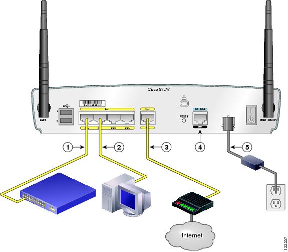
Figure 4-1 shows a typical installation of a Cisco 851 or Cisco 871 router. This figure shows the back panel of a Cisco 871 router, which has two USB ports. The Cisco 851 router does not have any USB ports; however, the connections on the other ports are the same for both the Cisco 851 and Cisco 871 routers.
Figure 4-1 Typical Installation of a Cisco 851 or Cisco 871 Router
Ethernet connection to an external switch
Console port
Ethernet connection to a PC
Power adapter
WAN connection using a broadband modem to the Internet
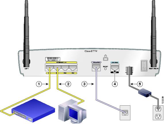
Figure 4-2 Typical Installation of a Cisco 857 or Cisco 877 Router
Ethernet connection to an external switch
Console port
Ethernet connection to a PC
Power adapter
ADSL-over-POTS connection
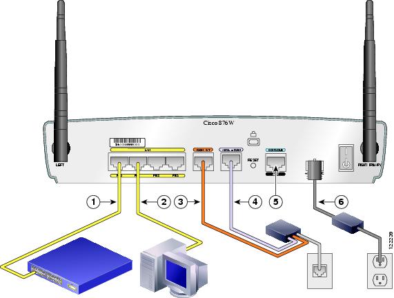
Figure 4-3 Typical Installation of a Cisco 876 Router
Ethernet connection to an external switch
ADSL-over-ISDN connection
Ethernet connection to a PC
Console port
ISDN S/T connection
Power adapter
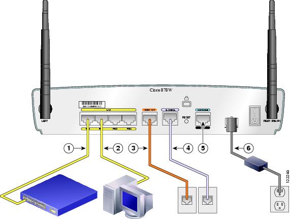
Figure 4-4 Typical Installation of a Cisco 878 Router
Ethernet connection to an external switch
G.SHDSL connection
Ethernet connection to a PC
Console port
ISDN S/T connection
Power adapter
Connecting the Radio Antennas to the Wireless Router
If you selected the wireless option for the router, follow these steps to attach the radio antennas:
Step 1
Step 2
a.
b.
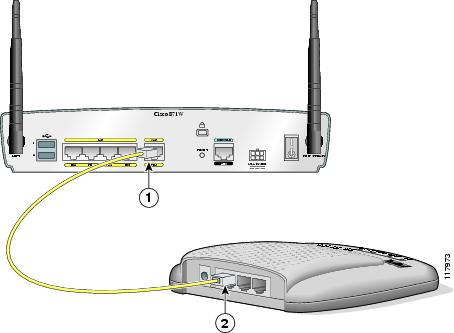
Connecting the Power-over-Ethernet Module (Optional)
If you purchased a power-over-Ethernet (PoE) module to provide inline power to devices, connect the four Ethernet cables on the PoE module to the four LAN Ethernet ports on the router. Make sure you connect all four Ethernet cables. If the cables are too close together for easy insertion, move the plastic cable guard away from the connector end of the cable. See Figure 4-5.
Caution
Figure 4-5 Connecting the Power-over-Ethernet Module to the Router
Router
PoE module
Router Ethernet ports
Plastic cable guard
Ethernet cables connecting the PoE module to the router
After you connect the PoE module to the router, connect the Ethernet devices to the ports on the PoE module, rather than to the Ethernet ports on the router.
Note
Connecting a Server, PC, or Workstation
To connect a server, PC, or workstation to a built-in Ethernet switch port, follow the steps given after Figure 4-6, which shows a Cisco 871 router connected to a PC. The procedure applies to Cisco 850 series and Cisco 870 series routers.
Figure 4-6 Connecting a Server, PC, or Workstation
Router
PC
Yellow Ethernet cable
RJ-45 port on the network interface card (NIC)
Built-in Ethernet switch port on the router
Perform the following steps to connect the PC (or other Ethernet devices) to a port on the built-in Ethernet switch.
Caution
Step 1
Step 2
Step 3
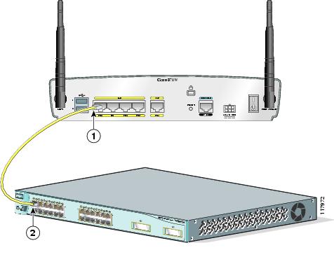
Connecting an External Ethernet Switch (Optional)
If more than four PCs need to be connected to each other in an office, you may connect an external Ethernet switch to the router's built-in switch to add additional Ethernet connections to the router.
Although Figure 4-7 shows a Cisco 871 router, the procedure in this section applies to all Cisco 850 series and Cisco 870 series routers.
To connect an external Ethernet switch to a built-in Ethernet switch port on the router, follow the steps given after Figure 4-7, which shows this connection.
Figure 4-7 Connecting to an Ethernet Switch
Yellow Ethernet cable connecting an external Ethernet switch to a built-in Ethernet switch port on the router
Available port on the external Ethernet switch
Perform the following steps to connect the router to an external Ethernet switch:
Step 1
Step 2
Step 3
Connecting a Broadband Modem
This section applies only to Cisco 851 and Cisco 871 routers. You can connect to the Internet by connecting a broadband modem. To connect to an installed DSL, cable, or long-reach Ethernet modem, follow the steps given after Figure 4-8, which shows this connection.
Figure 4-8 Connecting to a Broadband Modem
Perform the following steps to connect the router to an installed DSL, cable, or long-reach Ethernet modem:
Step 1
Step 2
Step 3
Step 4
Note
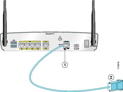
Connecting a Terminal or PC to the Console Port
The console port is a service port to which you can connect a terminal or PC either to configure the software by using the command-line interface (CLI) or to troubleshoot problems with the router.
Although Figure 4-9 shows a Cisco 871 router, the procedure in this section applies to all Cisco 850 series and Cisco 870 series routers.
To connect a terminal or PC to the console port, follow the steps given after Figure 4-9.
Figure 4-9 Connecting a Terminal or PC to the Console Port
Perform the following steps to connect the router's console port to a terminal or PC:
Step 1
Step 2
Connecting an Async Modem to the Console Port
The Cisco 850 series and Cisco 870 series routers support the dial backup function, which allows a user to connect an analog modem to the console port as a backup link to the WAN port in case the ADSL service goes down.
Note
Although Figure 4-10 shows the async modem connection to the console port on the Cisco 857 router, this connection applies to all Cisco 850 series and Cisco 870 series routers.
Figure 4-10 Connecting an Async Modem to the Console Port
Perform the following steps to connect the console port on the router to an async modem:
Step 1
Step 2
Step 3
Step 4
Connecting an ISDN S/T Port
This section applies to Cisco 876 and Cisco 878 routers. You can connect the ISDN S/T port to the ISDN service provider as a backup link to the WAN port in case the ADSL service goes down.
The cabling requirements and information for the ISDN S/T connection follow:
•
•
Caution
Although Figure 4-11 shows an ISDN S/T connection for a Cisco 876 router, this connection also applies to a Cisco 878 router.
Figure 4-11 Connecting the ISDN S/T Port to the ISDN Service Provider
Perform the following steps to connect the ISDN S/T port to the ISDN service provider:
Step 1
Step 2
Step 3
Step 4
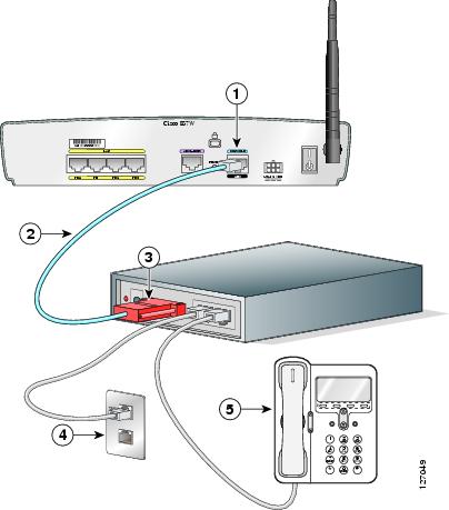
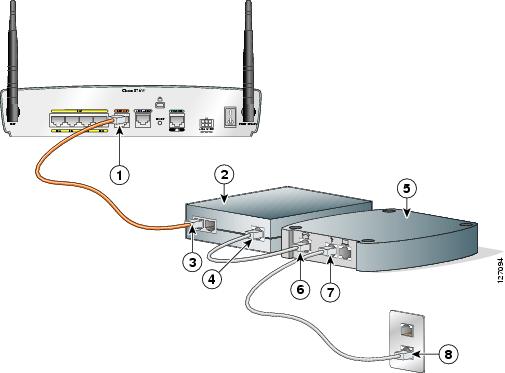
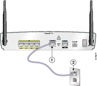
Connecting an ADSL Line—ADSLoPOTS Port
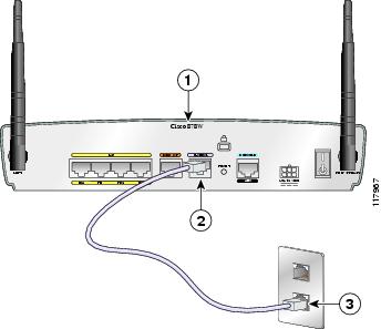
This section applies only to Cisco 857 and Cisco 877 routers. Follow the steps shown after Figure 4-12 to connect an asymmetric digital subscriber line (ADSL) over plain old telephone service (ADSLoPOTS) port on the router.
Note
Figure 4-12 Connecting the ADSLoPOTS Port to an ADSL Line
Caution
Please contact your sales team or qualified service person for further information and installation.
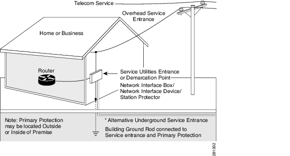
Figure 4-13
Primary Protection Device Location
Perform the following steps to connect the ADSL cable to a cable wall jack:
Step 1
Step 2
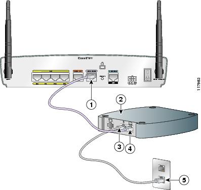
Connecting an ADSL Line—ADSLoISDN Port
This section applies only to the Cisco 876 router. The procedure for connecting an asymmetric digital subscriber line (ADSL) depends on the router and, in some cases, on the location. Follow the steps shown after Figure 4-15 to connect the ADSL cable to a cable wall jack.
Note
Note
Caution
Please contact your sales team or qualified service person for further information and installation.
Figure 4-14
Primary Protection Device Location
Figure 4-15 Connecting the ADSLoISDN Port to an ADSL Line
Perform the following steps to connect the ADSL line to a cable wall jack:
Step 1
Step 2
Step 3
Connecting a G.SHDSL Line
This section applies to the Cisco 878 router only. To connect the router to a G.SHDSL line, perform the steps given after Figure 4-16.
Figure 4-16 Connecting the G.SHDSL Line
Caution
Please contact your sales team or qualified service person for further information and installation.
Figure 4-17
Primary Protection Device Location
Perform the following steps to connect the router to an installed DSL:
Step 1
Step 2
Connecting the AC Adapter
To connect the AC adapter, follow the steps given after Figure 4-18. Although the illustration shows the Cisco 871 router, the procedure applies to all Cisco 850 series and Cisco 870 series routers.
WarningFigure 4-18 Connecting the AC Adapter (No PoE Module)
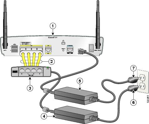
Figure 4-19 Connecting AC Adapters to the Router and to the PoE Module
Router
Router power adapter
Ethernet cables on the PoE module
PoE module power adapter plug
PoE module
Router power adapter plug
PoE module power adapter
Perform the following steps to connect power to the router and to the PoE module:
Step 1
Step 2
Step 3
Step 4
Verifying Router Operations
To verify that all devices are properly connected to the router, turn on all the connected devices; then use Table 4-1 to help you verify correct router operation by checking the LEDs.
What to Do Next
After verifying that the router cabling is correct and the power up is successful, perform the initial configuration of the router as described in Chapter 5 "Initial Configuration."