-
Cisco 7600-ES20 Ethernet Line Card Configuration Guide
-
Cisco 7600 Series Ethernet Services 20G
-
Preface
-
Overview of the Cisco 7600 Series Ethernet Services 20G Line Card
-
Configuring the Cisco 7600 Series Ethernet Services 20G Line Card
-
Configuring QoS on the Cisco 7600 Series Ethernet Services 20G Line Card
-
Command Summary for the Cisco 7600 Series Ethernet Services 20G Line Card
-
Troubleshooting the Cisco 7600 Series Ethernet Services 20G Line Card
-
 Feedback
Table Of Contents
Configuring the Cisco 7600 Series Ethernet Services 20G Line Card
Identifying Slots and Subslots for the Cisco 7600 Series Ethernet Services 20G Line Card
Configuring High-Availability Features
Configuring UDE on ES20 Line Cards
Restrictions and Usage Guidelines
Configuring Unidirectional Link Detection (UDLD) on Ports with EVCs
Restrictions and Usage Guidelines
Configuring UDLD Aggressive Mode
Enabling UDLD on Ports With EVC Configured
Disabling Individual UDLD on Ports With EVC Configured
Resetting Disabled UDLD on Ports With EVC Configured
ISSU Support for ES20 Line Card
Configuring IEEE 802.1ag-2007 Compliant CFM
Restrictions and Usage Guidelines
Prerequisites for IEEE 802.1ad
Information About IEEE 802.1ad
Configuring EVC EtherChannel and LACP over EVC Port Channel
Restrictions and Usage Guidelines
Multichassis Support for Link Aggregation Control Protocol
Pseudo MLACP Support on Cisco 7600
Configuring PMLACP on Cisco 7600
Configuring Custom Ethertype for EVC Interfaces
Supported Rewrite Rules for a Custom Ethertype Configuration
Supported Rewrites for Non Range on a C-Tag on an NNI
Supported Rewrites for Range on C-Tag with an NNI
Restrictions and Usage Guidelines
Configuring Flexible QinQ Mapping and Service Awareness on 7600-ESM-2X10GE and 7600-ESM-20X1GE
Restrictions and Usage Guidelines
Configuring Flexible Service Mapping Based on CoS and Ethertype
Restrictions and Usage Guidelines
Configuring MultiPoint Bridging over Ethernet on 7600-ESM-2X10GE and 7600-ESM-20X1GE
Restrictions and Usage Guidelines
Configuring Gigabit Ethernet Link Aggregation with Advanced Load Balancing
Restriction and Usage Guidelines
Troubleshooting Load Balancing Features
Configuring Virtual Private LAN Service (VPLS) with Port-Channel as a Core Interface
TE-FRR Support on VPLS LAG NNI
Fat Pseudo-Wire Load Balancing
Provider Router Load Balancing
Restrictions and Usage Guidelines
Configuring BPDU PW on a Port Channel
Configuring the Backup Interface for Flexible UNI
Restriction and Usage Guidelines
Configuring Layer2 Access Control Lists (ACLs) on an EVC
Restrictions and Usage Guidelines
Configuring Broadcast Storm Control on Switchports and Ports with Ethernet Virtual Connections
Traffic Storm Control on ES20 Switchports
Restrictions and Usage Guidelines
Traffic Storm Control on ES20 with EVCs
Restrictions and Usage Guidelines
Configuring Asymmetric Carrier-Delay
Restrictions and Usage Guidelines
Configuring MST on EVC Bridge Domain
Overview of MST on EVC Bridge Domain
Restrictions and Usage Guidelines
DHCP Snooping with Option-82 on EVC
Restrictions and Usage Guidelines
Configuring MAC Address Security for EVC Bridge-Domain
Restrictions and Usage Guidelines
Configuring MAC Address Security for EVC Bridge-Domain
Enabling MAC Address Security for EVC Bridge-Domain
Disabling MAC Address Security for EVC Bridge-Domains on an EFP
Configuring Whitelisted MAC Address on an EFP
Configuring Sticky MAC Addresses on an EFP
Configuring Secure MAC Address Aging on an EFP
Configuring MAC Address Limiting on an EFP
Configuring MAC Address Limiting on a Bridge-Domain
Configuring Violation Response on an EFP
Configuring Static MAC on Ethernet Flow Point and Pseudowire
Restrictions and Usage Guidelines
Configuring Static MAC over EFP for the Cisco 7600 Router
Configuring MPLS on Core-Facing Interface
Configuring Static MAC over Pseudowire for the Cisco 7600 Router
Configuring Resilient Ethernet Protocol
Configuring REP over Ethernet Virtual Circuit
Restrictions and Usage Guidelines
Configuring REP over EVC for the Cisco 7600 Router
Configuring REP over EVC using Cross connect for the Cisco 7600 Router
Configuring REP over EVC using connect for the Cisco 7600 Router
Configuring REP over EVC using bridge domain for the Cisco 7600 Router
Configuring Resilient Ethernet Protocol Configurable Timers
Restrictions and Usage Guidelines
Configuring REP Configurable Timers for the Cisco 7600 Router
Configuring the REP Link Status Layer Retries
Configuring the REP Link Status Layer Age Out Timer
Configuring the REP Link Status Layer Age Out Timer
Configuring CFM over EFP Interface with cross connect
Restrictions and Usage Guidelines
Configuring CFM over EFP with xconnect for the Cisco 7600 Router
Configuring CFM over EFP Interface with Cross Connect—Basic Configuration
Configuring CFM over EFP Interface with Cross Connect—Single Tag VLAN Cross Connect
Configuring CFM over EFP Interface with Cross Connect—Double Tag VLAN Cross Connect
Configuring CFM over EFP Interface with Cross Connect—Selective QinQ Cross Connect
Configuring CFM over EFP Interface with Cross Connect—Port-Based Cross Connect Tunnel
Configuring CFM over EFP Interface with Cross Connect—Port Channel-Based Cross Connect Tunnel
Configuring Reverse Layer 2 Gateway Ports for the Cisco 7600 Router
Restrictions and Usage Guidelines
Configuring Reverse L2GP for the Cisco 7600 Router
Configuring Private Host Switch Virtual Interface (VLAN and VPLS)
Verifying the Private Hosts SVI configuration
Sample Configuration For Private Hosts VPLS Configuration
Sample configuration for Private Hosts Interface Vlan configuration
Configuring Multicast Features
Configuring IGMP/PIM Snooping for VPLS Pseudowire on 7600-ESM-2X10GE and 7600-ESM-20X1GE
Restrictions and Usage Guidelines
Configuring Link State Tracking (LST)
Restrictions and Usage Guidelines
Configuring Link-State Tracking
Troubleshooting the Link State Tracking
Configuring Multicast VLAN Registration
Using MVR in a Multicast Television Application
Configuring Layer 3 and Layer 4 Features
Configuring Layer 3 and Layer 4 Access Control List on a Service Instance
Restrictions and Usage Guidelines
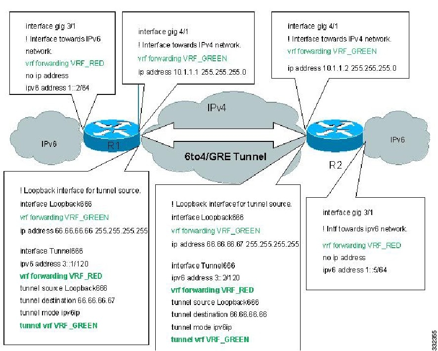
Restrictions for VRF aware IPv6 tunnels
Configuring VRF aware IPv6 tunnel
Configure IPv6 overlay addresses in VRF and IPv4 transport addresses in Global RT
Configure IPv6 overlay addresses in VRF and IPv4 transport addresses in VRF
Configuring Any Transport over MPLS
Scalable EoMPLS on 7600-ESM-2X10GE and 7600-ESM-20X1GE
Restrictions and Usage Guidelines
Configuring MPLS Traffic Engineering Class-Based Tunnel Selection
Restrictions and Usage Guidelines
Creating Multiple MPLS Member TE or DS-TE Tunnels with the Same Headend and the Same Tailend
Creating a Master Tunnel, Attaching Member Tunnels, and Making the Master Tunnel Visible
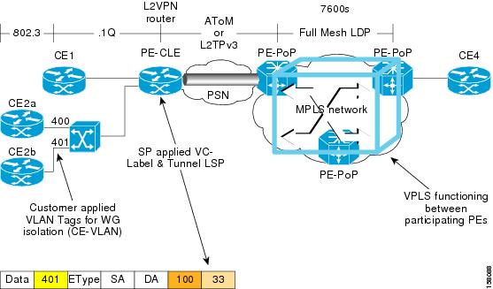
Configuring Virtual Private LAN Service
Hierarchical Virtual Private LAN Service (H-VPLS) with MPLS to the Edge
Configuring SVI-Based IP/Routed Interworking
Restrictions and Usage Guidelines
Resetting a Cisco 7600 Series Ethernet Services 20G Line Card
Configuring the Cisco 7600 Series Ethernet Services 20G Line Card
This chapter provides information about configuring the Cisco 7600 Series Ethernet Services 20G (ES20) line card on the Cisco 7600 series router. It includes the following sections:
•
Configuring High-Availability Features
•
•
•
•
•
•
•
•
•
•
•
•
•
•
•
•
•
•
•
•
•
•
•
•
•
•
•
•
•
•
•
•
•
•
For information about managing your system images and configuration files, refer to the Cisco IOS Configuration Fundamentals Configuration Guide and Cisco IOS Configuration Fundamentals Command Reference publications that correspond to your Cisco IOS software release.
For more information about some of the commands used in this chapter, see
Chapter A, "Command Summary for the Cisco 7600 Series Ethernet Services 20G Line Card," and the Cisco IOS Release 12.2 SR Command References at http://www.cisco.com/en/US/products/ps6922/prod_command_reference_list.html
Also refer to the related Cisco IOS software command reference and master index publications. For more information about accessing these publications, see the "Related Documentation" section.
Required Configuration Tasks
As of Cisco IOS Release 12.2SRB, there are not many features that require direct configuration on the ES20 line card. You do not need to attach to the ES20 line card itself to perform any configuration.
Identifying Slots and Subslots for the Cisco 7600 Series Ethernet Services 20G Line Card
The ES20 line card supports In-Service Software Upgrade (ISSU) with Enhanced Fast Software Upgrade (eFSU). ISSU allows for the upgrade and downgrade of Cisco IOS images at different release levels on the active and standby supervisors. ISSU procedure also applies to upgrade and downgrade of line card images. A new line card image is loaded, as necessary, when the supervisor engine software is upgraded or downgraded.
For more information, see the Cisco 7600 Series Cisco IOS Software Configuration Guide, 12.2SR at http://www.cisco.com/en/US/docs/routers/7600/ios/12.2SR/configuration/guide/swcg.html
Configuring High-Availability Features
This section provides information about configuring high-availability features specific to the ES20 line card.
Configuring UDE on ES20 Line Cards
Unidirectional Ethernet (UDE) feature allows interfaces to operate as unidirectional links, that is, either in receive (Rx) only mode or transmit (Tx) only mode. Unidirectional Ethernet uses only one strand of fiber for either transmitting or receiving one-way traffic for Gig Ports instead of two strands of fiber for a full duplex operation.
UDLR mechanism allows a set of feeds and receivers, which are directly connected by a unidirectional link, to send datagrams as if they were all connected by a bidirectional link.
Unidirectional Routing is used in applications with a great amount of data traffic flowing in one direction and little control traffic flowing in the opposite direction.
When an interface is configured as unidirectional send-only or receive-only, the following actions take place:
•
•
•
Restrictions and Usage Guidelines
The following restrictions apply to the UDE links on ES20 line cards:
•
•
•
•
•
•
•
•
•
•
•
•
•
•
•
SUMMARY STEPS
1.
2.
3.
4.
5.
DETAILED STEPS
Examples
Router A Configuration
In this example, interface 10.1.0.1 on Router A is configured as the send-only port while the tunnel running from 11.0.0.1 to 11.0.0.2 is configured as the receive-only interface.
interface tengigabitethernet 1/0/0unidirectional send-onlyip address 10.1.0.1 255.255.0.0ip pim sparse-dense-mode!! Configure tunnel as receive-only UDLR tunnel!interfacetunnel 0tunnel source 11.0.0.1tunnel destination 11.0.0.2tunnel udlr receive-only tengigabitethernet 1/0/0Router B Configuration
In this example, interface 10.1.0.2 on Router B is configured as the receive-only port while the tunnel running from 11.0.0.2 to 11.0.0.1 is configured as the receive-only interface.
Config e.g 1interface tengigabitethernet 1/0/0unidirectional receive-onlyip address 10.1.0.2 255.255.0.0ip pim sparse-dense-mode!! Configure tunnel as send-only UDLR tunnel.!interface tunnel 0tunnel source 11.0.0.2tunnel destination 11.0.0.1tunnel udlr send-only tengigabitethernet 1/2tunnel udlr address-resolutionConfig e.g 2interface GigabitEthernet1/0/0switchportswitchport access vlan 100switchport mode accessno ip addressspeed nonegotiateunidirectional send-onlyinterface Vlan100ip address 10.0.1.1 255.255.255.0ip pim sparse-modeSwitched Port UDE Configuration
This example shows UDE configuration on a switched port with an SVI interface, with OSPF enabled.
Topology :[UDE-R1]-----UDE--------->[UDE-R2]<-------UDLR-------UDE-R1#sh run int gig2/0/5Building configuration...Current configuration : 165 bytes!interface GigabitEthernet2/0/5switchportswitchport access vlan 300switchport mode accessspeed nonegotiateno mls qos trustunidirectional send-onlyendUDE-R1#sh run int tunnel 10Building configuration...Current configuration : 150 bytes!interface Tunnel10ip address 70.10.10.1 255.255.255.0tunnel source 50.0.0.1tunnel destination 50.0.0.2tunnel udlr receive-only Vlan300endUDE-R1#sh run int vlan 300Building configuration...Current configuration : 104 bytes!interface Vlan300ip address 90.90.90.99 255.255.255.0endrouter ospf 1log-adjacency-changesnetwork 20.0.0.0 0.0.0.255 area 0network 90.90.90.0 0.0.0.255 area 0############ config on R2####################UDE-R2#sh run int gig2/0/1Building configuration...Current configuration : 170 bytes!interface GigabitEthernet2/0/1switchportswitchport access vlan 300switchport mode accessspeed nonegotiatemls qos trust dscpunidirectional receive-onlyendUDE-R2#sh run int tunnel 10Building configuration...Current configuration : 179 bytes!interface Tunnel10ip address 70.10.10.2 255.255.255.0tunnel source 50.0.0.2tunnel destination 50.0.0.1tunnel udlr send-only Vlan300tunnel udlr address-resolutionendUDE-R2#sh run int vlan 300Building configuration...Current configuration : 82 bytes!interface Vlan300ip address 90.90.90.90 255.255.255.0endrouter ospf 1log-adjacency-changesnetwork 30.0.0.0 0.0.0.255 area 0network 90.90.90.0 0.0.0.255 area 0Verification
Use the following commands to verify operation.
Configuring Unidirectional Link Detection (UDLD) on Ports with EVCs
UDLD (Unidirectional Link Detection) is a Layer 2 protocol that interacts with a Layer 1 protocol to determine the physical status of a link. At Layer 1, physical signaling and fault detection is auto-negotiated. UDLD detects the neighbor link, identifies, and disables the wrongly connected LAN ports. When you enable auto-negotiation and UDLD, Layer 1 and Layer 2 detections prevent physical and logical unidirectional connections, and malfunctioning of other protocols.
A unidirectional link occurs when the neighbor link receives the traffic transmitted by the local device, but the local device does not receive the transmitted traffic from its neighbor. If auto-negotiation is active, and one of the fiber strands in a pair is disconnected, the link is disabled. The logical link is undetermined, and UDLD does not take any action. At Layer 1, if both fibers are normal, UDLD at Layer 2 determines if the fibers are accurately connected, and traffic is relayed bidirectionally between the right neighbors. In this scenario, auto-negotiation operates in Layer 1, and the link status is unchecked.
The UDLD protocol monitors physical configuration of the cables, and detects unidirectional links of devices connected to LAN ports via Ethernet cables. When a unidirectional link is detected, UDLD disables the affected LAN port, and alerts the user.
The Cisco 7600 series router periodically transmits UDLD packets to neighboring devices on LAN ports with UDLD. If the packets are returned within a specific time frame, and there is no acknowledgement, the link is flagged as unidirectional, and the LAN port is disabled.
Restrictions and Usage Guidelines
Follow these restrictions and usage guidelines while configuring UDLD on ports with EVCs:
•
•
•
•
•
Note
For more information on UDLD, see the Cisco 7600 Series Cisco IOS Software Configuration Guide, 12.2SR at the following URL:
http://www.cisco.com/en/US/docs/routers/7600/ios/12.2SR/configuration/guide/udld.html
Configuring UDLD Aggressive Mode
As UDLD aggressive mode is disabled by default, you can configure UDLD aggressive mode in point-to-point links between network devices that support UDLD aggressive mode.
When UDLD aggressive mode is enabled:
•
•
•
To prevent spanning tree loops, ensure that you set the non aggressive UDLD value interval to 15 seconds. This disables the unidirectional link before blocking the port transitions in the forwarding state (with default spanning tree parameters).
The benefits of enabling UDLD aggressive mode are:
•
•
In the above scenario, UDLD aggressive mode disables the port that prevents traffic from being discarded.
Enabling UDLD on Ports With EVC Configured
SUMMARY STEPS
1.
2.
3.
4.
DETAILED STEPS
SUMMARY STEPS
1.
2.
3.
4.
DETAILED STEPS
Disabling Individual UDLD on Ports With EVC Configured
SUMMARY STEPS
1.
2.
3.
4.
DETAILED STEPS
Resetting Disabled UDLD on Ports With EVC Configured
SUMMARY STEPS
1.
DETAILED STEPS
Step 1
udld reset
Example:Router# udld resetResets all the LAN ports disabled by UDLD.
Example
This example displays the global configuration values at router 1:
Router(config)#udld enableThis example displays the ESM20 port at router 1:
Router(config)# inter gi 2/0/1Router(config-if)# udld port aggressiveRouter(config-if)# service instance 1 ethernetRouter(config-if-srv)# encapsulation dot1q 100Router(config-if-srv)# rewrite ingess tag translate 1-to2 dot1q 5 second-dot1q 5 symmetricRouter(config-if-srv)# bridge-domain 100This example displays the configuration for a port that is part of a port channel:Router(config)#interface Port-channel1Router(config-if)#no ip addressRouter(config-if)#service instance 1 ethernetRouter(config-if)#encapsulation untaggedRouter(config-if)#bridge-domain 100Router(config)#interface GigabitEthernet3/0/13Router(config-if)#ip arp inspection limit noneRouter(config-if)#no ip addressRouter(config-if)#udld port aggressiveRouter(config-if)#no mls qos trustRouter(config-if)#channel-group 1 mode onVerification
Use the show udld and show udld interface commands to verify the UDLD configuration:
Router(config)show udld gi 3/0/13Interface Gi1/3---Port enable administrative configuration setting: Enabled / in aggressive modePort enable operational state: Enabled / in aggressive modeCurrent bidirectional state: BidirectionalCurrent operational state: Advertisement - Single neighbor detectedMessage interval: 15Time out interval: 5Entry 1---Expiration time: 37Cache Device index: 1Current neighbor state: BidirectionalDevice ID: 011932118C0Port ID: Gi1/1Neighbor echo 1 device: 0FF71CA880Neighbor echo 1 port: Gi1/3Message interval: 15Time out interval: 5CDP Device name: rish2ISSU Support for ES20 Line Card
The ES20 line card supports In-Service Software Upgrade (ISSU) with Enhanced Fast Software Upgrade (eFSU). ISSU allows for the upgrade and downgrade of Cisco IOS images at different release levels on the active and standby supervisors. ISSU procedure also applies to upgrade and downgrade of line card images. A new line card image is loaded, as necessary, when the supervisor engine software is upgraded or downgraded.
Configuring IEEE 802.1ag-2007 Compliant CFM
A Metro Ethernet network consists of networks from multiple operators supported by one service provider and connects multiple customer sites to form a virtual private network (VPN). Networks provided and managed by multiple independent service providers have restricted access to each other's equipment. Because of the diversity in these multiple-operator networks, failures must be isolated quickly. As a Layer 2 network, Ethernet must be capable of reporting network faults at Layer 2.
IEEE 802.3ah is a point-to-point and per- physical- wire OAM protocol that detects and isolates connectivity failures in the network. IEEE 802.1ag draft 8.1 Metro Ethernet Connectivity Fault Management (CFM) incorporates several OAM facilities that allow you to manage Metro Ethernet networks, including an Ethernet continuity check, end-to-end Ethernet traceroute facility using Linktrace message (LTM), Linktrace reply (LTR), Ethernet ping facility using Loopback Message (LBM), and a Loopback Reply (LBR). These Metro Ethernet CFM protocol elements quickly identify problems in the network.
Ethernet Connectivity Fault Management (CFM) is an end-to-end per-service-instance Ethernet layer operations, administration, and maintenance (OAM) protocol. It includes proactive connectivity monitoring, fault verification, and fault isolation for large Ethernet metropolitan-area networks (MANs) and WANs. Connectivity Fault Management (CFM) is the indispensable capability that service providers require to deploy large-scale, multivendor Metro Ethernet services. This feature upgrades the implementation of CFM to be compliant with the IEEE 802.1ag with the current standard, 802.1ag-2007 and implementation of CFM over L2VFI (Layer 2 Virtual Forwarding Instance Information), cross connect, EVC, and Switchport.
Key CFM mechanisms are:
•
•
•
•
For more information on CFM, see Cisco IOS Carrier Ethernet Configuration Guide, Release 12.2SR at
http://www.cisco.com/en/US/docs/ios-xml/ios/cether/configuration/12-2sr/ce-12-2sr-book.html
For more information about the commands used in this section, see Cisco IOS Ethernet Command Reference Guide at http://www.cisco.com/en/US/docs/ios/cether/command/reference/ce_book.html
Supported Line Cards
Use the ethernet cfm global command to enable the CFM D8.1 feature on the following line cards:
•
•
•
•
The complete support matrix for the CFM D8.1 feature is given in Table 2-1and Table 2-2.
Note
Table 2-1 Supported Matrix1
Table 2-2 Supported Matrix 2
Scalable Limits
Table 2-3 maps the supported interfaces with the CFM points and their scalability values:
Table 2-3
Scalable Limits
Restrictions and Usage Guidelines
When configuring CFM D8.1, follow these restrictions and usage guidelines:
•
•
•
•
•
•
•
•
•
Sample D1 configuration during migration:
ethernet cfm domain 2OUT493 level 2 direction outwardservice 1 evc 493Sample configuration to avoid the migration issue:
ethernet cfm domain 2OUT493 level 2 direction outwardservice 1 evc 493service 1 vlan 493SUMMARY STEPS (COMMON CONFIGURATIONS FOR EVC, SWITCHPORT, AND ROUTED PORTS)
1.
2.
3.
4.
5.
6.
7.
DETAILED STEPS (COMMON CONFIGURATIONS FOR EVC, SWITCHPORT, AND ROUTED PORTS)
SUMMARY STEPS TO CONFIGURE CFM MEP AND MIP ON A EVC
1.
2.
3.
4.
5.
6.
7.
8.
9.
10.
DETAILED STEPS TO CONFIGURE CFM MEP AND MIP ON A EVC
SUMMARY STEPS TO CONFIGURE CFM MEP AND MIP ON A SWITCH PORT
1.
2.
3.
4.
5.
6.
or
7.
8.
DETAILED STEPS TO CONFIGURE CFM MEP AND MIP ON A SWITCHPORT
SUMMARY STEPS TO CONFIGURE CFM MEP ON A ROUTED PORT
1.
2.
3.
4.
5.
6.
7.
8.
9.
DETAILED STEPS TO CONFIGURE CFM MEP ON A ROUTED PORT
Verification
Use the following commands to verify operation.
The following example shows a configuration of MEP in a switchport:
ethernet cfm domain L4 level 4service s41 evc 41 vlan 41continuity-checkint TenGigabitEthernet2/0/0switchportswitchport mode trunkethernet cfm mep domain L4 mpid 1 vlan 41The following example shows a configuration of MIP in a switchport:
ethernet cfm domain L4 level 4service s41 evc 41 vlan 41continuity-checkint TenGigabitEthernet2/0/0switchportswitchport mode trunkethernet cfm mip level 4 vlan 41The following example shows a configuration of MEP in a EVC bridge domain:
ethernet cfm domain L4 level 4service s41 evc 41 vlan 41continuity-checkint TenGigabitEthernet4/0/0service instance 41 ethernet 41encapsulation dot1q 41bridge-domain 41cfm mep domain L4 mpid 4001The following example shows a configuration of MIP in a EVC bridge domain:
ethernet cfm domain L4 level 4service s41 evc 41 vlan 41continuity-checkint TenGigabitEthernet4/0/0service instance 41 ethernet 41encapsulation dot1q 41bridge-domain 41cfm cfm mip level 4The following example shows a configuration of MEP on a routed port:
ethernet cfm domain routed level 5service s2 evc 2 vlan 2 direction downcontinuity-checkinterface GigabitEthernet8/0/0no ip addressno mls qos trustethernet cfm mep domain routed mpid 4001 vlan 4001interface GigabitEthernet8/0/0.10encapsulation dot1Q 10The following example shows CFM configuration over a EVC with cross connect in the global domain configuration mode:
ethernet cfm domain L6 level 6service xconn evc xconncontinuity-checkThe following example shows CFM configuration over a EVC with cross connect in the interface configuration mode:
ethernet cfm domain L6 level 6service s100 evc 100continuity-checkinterface Port-channel10no ip addressservice instance 100 ethernet 100encapsulation dot1q 200xconnect 3.3.3.3 1 encapsulation mplscfm mep domain L6 mpid 602cfm mip level 7!
The following example shows CFM configuration on a L2VFI:
Router(config)# l2 vfi vfi2 manual evc2Router(config-vfi)# vpn id 2Router(config-vfi)# bridge-domain 2 vlanRouter(config-vfi)# no shutRouter(config-vfi)# neighbor 5.5.5.5 encap mplsRouter(config-vfi-neighbor)# interface vlan 2Router(config-if)# xconnect vfi vfi2Router(config-if)# no shutRouter(config-if)# ethernet cfm domain vik-vfi-ofm level 4Router(config-ecfm)# service vlan-id 2 evc evc2 vlan 2 direction downRouter(config-ecfm-srv)# continuity-checkRouter(config-ecfm-srv)# continuity-check interval 10sSupport for IEEE 802.1ad
Provider networks handle traffic from a large number of customers. It is important that one customer's traffic is isolated from the other customer's traffic. IEEE 802.1ad implements standard protocols for double tagging of data. The data traffic coming from the customer side are double tagged in the provider network where the inner tag is the customer-tag (C-tag) and the outer tag is the provider-tag (S-tag). The control packets are tunneled by changing the destination MAC address in the provider network.
Cisco 7600 series routers already support VLAN double tagging through a feature called QinQ. 802.1ad is the standardized version of QinQ. It also extends the support for Layer 2 Protocol Tunneling Protocol (L2PT). By offering transparent Layer 2 connectivity, the service provider does not get involved in the customer's Layer 3 network. This makes provisioning and maintenance simple, and reduces the operational cost.
Prerequisites for IEEE 802.1ad
•
Restrictions for IEEE 802.1ad
Follow these restrictions and guidelines when you configure 802.1ad:
•
•
•
•
•
Information About IEEE 802.1ad
To configure IEEE 802.1ad support, you should understand the following concepts:
•
How Provider Bridges Work
Provider bridges pass the network traffic of many customers, and each customer's traffic flow must be isolated from one another. For the Layer 2 protocols within customer domains to function properly, geographically separated customer sites must appear to be connected through a LAN, and the provider network must be transparent.
The IEEE has reserved 33 Layer 2 MAC addresses for customer devices operating Layer 2 protocols. If a provider bridge uses these standard MAC addresses for its Layer 2 protocols, the customers' and service provider's Layer 2 traffic will be mixed together. Provider bridges solve this traffic-mixing issue by providing Layer 2 protocol data unit (PDU) tunneling for customers using a provider bridge (S-bridge) component and a provider edge bridge (C-bridge) component. Figure 2-1 shows the topology.
Figure 2-1
Layer 2 PDU Tunneling
S-Bridge Component
The S-bridge component is capable of inserting or removing a service provider VLAN (S-VLAN) for all traffic on a particular port. IEEE 802.1ad adds a new tag called a Service tag (S-tag) to all the ingress frames from a customer to the service provider.
The VLAN in the S-tag is used for forwarding the traffic in the service provider network. Different customers use different S-VLANs, which results in each customer's traffic being isolated. In the S-tag, provider bridges use an Ethertype value that is different from the standard 802.1Q Ethertype value, and do not understand the standard Ethertype. This difference makes customer traffic tagged with the standard Ethertype appear as untagged in the provider network so customer traffic is tunneled in the port VLAN of the provider port. The 802.1ad service provider user network interfaces (S-UNIs) and network to network interfaces (NNIs) implement the S-bridge component.
For example, a VLAN tag has a VLAN ID of 1, the C-tag Ethertype value is 8100 0001, the S-tag Ethertype value is 88A8 0001, and the class of service (CoS) is zero.
C-tag S-tag------------------------------------------------------- -----------------------------------------------0x8100 | Priority bits | CFI | C-VLAN-ID 0x88A8 | Priority bits | 0 | S-VLAN-ID------------------------------------------------------- -----------------------------------------------C-Bridge Component
All the C-VLANs entering on a UNI port in an S-bridge component are provided the same service (marked with the same S-VLAN). Although, C-VLAN components are not supported, a customer may want to tag a particular C-VLAN packet separately to differentiate between services. Provider bridges allow C-VLAN packet tagging with a provider edge bridge, called the C-bridge component of the provider bridge. C-bridge components are C-VLAN aware and can insert or remove a C-VLAN 802.1Q tag. The C-bridge UNI port is capable of identifying the customer 802.1Q tag and inserting or removing an S-tag on the packet on a per service instance or C-VLAN basis. A C-VLAN tagged service instance allows service instance selection and identification by C-VLAN. The 802.1ad customer user network interfaces (C-UNIs) implement the C-component.
MAC Addresses for Layer 2 Protocols
Customers' Layer 2 PDUs received by a provider bridge are not forwarded, so Layer 2 protocols running in customer sites do not know the complete network topology. By using a different set of addresses for the Layer 2 protocols running in provider bridges, IEEE 802.1ad causes customers' Layer 2 PDUs entering the provider bridge to appear as unknown multicast traffic and forwards it on customer ports (on the same S-VLAN). Customers' Layer 2 protocols can then run transparently.
Table 2-4 shows the Layer 2 MAC addresses reserved for the C-VLAN component.
Table 2-5 shows the Layer 2 MAC addresses reserved for an S-VLAN component. These addresses are a subset of the C-VLAN component addresses, and the C-bridge does not forward the provider's bridge protocol data units (BPDUs) to a customer network.
Guidelines for Handling BPDU
The general BPDU guidelines are listed here:
UNI-C Ports
The guidelines pertaining to UNI-C ports are:
•
•
Table 2-6 shows the Layer 2 PDU destination MAC addresses for customer-facing C-bridge UNI ports, and how frames are processed.
UNI-S Ports
The guidelines pertaining to UNI-S ports are:
•
•
•
Table 2-7 shows the Layer 2 PDU destination MAC addresses for customer-facing S-bridge UNI ports, and how frames are processed.
NNI Ports
The Dot1add NNI ports behave in the same way as the customer facing S-bridge ports, with the following exceptions:
•
•
7600 Action Table
Table 2-8 lists the actions performed on a packet when the packet is received with a specified destination MAC address.
Interoperability of QinQ and Dot1ad
The interoperability of QinQ and Dot1ad network enables the exchange of data frames between the networks. The 802.1Q network outer tag VLANs are mapped to the provider S-VLANs of the 802.1ad network.
Figure 2-2 illustrates the interoperability of a Dot1ad network and a QinQ network.
Figure 2-2
Interoperability of Dot1ad Network and a QinQ Network
How to Configure IEEE 802.1ad
This section contains the information about following procedures:
•
•
•
•
•
•
•
•
Configuring a Switchport
A switchport can be configured as a UNI-C port, UNI-S port, or NNI port.
UNI-C Port
A UNI-C port can be configured as either a trunk port or an access port. Perform the following tasks to configure a UNI-C port as an access port for 802.1ad.
SUMMARY STEPS
1.
2.
3.
4.
5.
6.
7.
8.
DETAILED STEPS
Perform the following tasks to configure a UNI-C port as a trunk port for 802.1ad.
SUMMARY STEPS
1.
2.
3.
4.
5.
6.
7.
8.
DETAILED STEPS
UNI-S Port
On a UNI-S port, all the customer VLANs that enter are provided with the same service. The port allows only access configuration. In this mode, the customer's port is configured as a trunk port. Therefore, the traffic entering the UNI-S port is tagged traffic.
Perform the following tasks to configure a UNI-S port as an access port for 802.1ad.
SUMMARY STEPS
1.
2.
3.
4.
5.
6.
7.
8.
DETAILED STEPS
NNI Port
NNI port allows only trunk configuration. On an NNI port, the frames received on all the allowed VLANs are bridged to the respective internal VLANs.
Perform the following tasks to configure an NNI port as a trunk port for 802.1ad.
SUMMARY STEPS
1.
2.
3.
4.
5.
6.
7.
8.
DETAILED STEPS
Examples
The following example shows how to configure a UNI-C port as an access port. In this example, all the frames that are received are bridged to one internal VLAN 1000. The transmitted frames do not have the access VLAN Dot1q tag.
router# configure terminalrouter(config)#interface gig2/1router(config-if)#ethernet dot1ad uni c-portrouter(config-if)#switchportrouter(config-if)#switchport mode accessrouter(config-if)#switchport access vlan 1000The following example shows how to configure a UNI-C port as a trunk port. In this example, all the frames that are received on all allowed VLANs (1000 and 2000) are bridged to the respective internal VLANs. The transmitted frames have the respective internal VLAN Dot1q tag.
router# configure terminalrouter(config)# interface gig2/1router(config-if)# ethernet dot1ad uni c-portrouter(config-if)# switchportrouter(config-if)# switchport mode trunkrouter(config-if)# switchport access vlan 1000, 2000The following example shows how to configure a UNI-S port. In this example, all the frames that are received are bridged to one internal VLAN (999). The transmitted frames do not have the access VLAN Dot1q tag.
router# configure terminalrouter(config)#interface gig2/1router(config-if)#switchportrouter(config-if)#switchport mode accessrouter(config-if)#ethernet dot1ad uni s-portrouter(config-if)#switchport access vlan 999The following example shows how to configure an NNI port. Only trunk configuration is allowed on an NNI port. In this example, all the frames that are received on all the allowed VLANs (999) are bridged to the respective internal VLANs. The transmitted frames have the respective internal VLAN Dot1q tag.
router# configure terminalrouter(config)#interface gig2/1router(config-if)#switchportrouter(config-if)#switchport mode trunkrouter(config-if)#ethernet dot1ad nnirouter(config-if)#switchport trunk allowed vlan 999The following example shows how to configure Dot1ad on an SVI:
router# configure terminalrouter(config)#interface gig2/1router(config-if)#ethernet dot1ad nnirouter(config-if)#switchportrouter(config-if)#switchport mode trunkrouter(config-if)#switchport trunk allowed vlan 999 router(config)#interface vlan 999 router(config-if)#ip address 1.2.3.4 255.255.0.0Configuring a Layer 2 Protocol Forward
Perform the following tasks to configure the Layer 2 protocol forward:
SUMMARY STEPS
1.
2.
3.
4.
5.
6.
7.
DETAILED STEPS
Examples
The following example shows how to configure a Layer 2 protocol forward:
router# configure terminalrouter(config)#interface gig3/0router(config-if)#switchport access vlan 500router(config-if)#ethernet dot1ad uni s-portrouter(config-if)#l2protocol forward vtpConfiguring a Switchport for Translating QinQ to 802.1ad
Translating a QinQ port to 802.1ad involves configuring the port connecting to QinQ port and NNI port.
Perform the following tasks to configure a port connecting to the QinQ port.
SUMMARY STEPS
1.
2.
3.
4.
5.
6.
DETAILED STEPS
Perform the following tasks to configure an NNI port.
SUMMARY STEPS
1.
2.
3.
4.
5.
6.
7.
8.
DETAILED STEPS
Examples
The following example shows how to translate a QinQ port to 802.1ad. In this example, the peer router to gig1/1 multiplexes various customer VLANs into VLAN 1000.
router# configure terminalrouter(config)#interface gig1/1router(config-if)#switchport mode trunkrouter(config-if)#switchport trunk allowed vlan 1000router# configure terminalrouter(config)#interface gig4/0router(config-if)#ethernet dot1ad nnirouter(config-if)#switchportrouter(config-if)#switchport mode trunkrouter(config-if)#switchport trunk allowed vlan 1000,1199Configuring a Switchport (L2PT)
Configuring the switchport for L2PT is required to tunnel the STP packets from a customer on the dot1ad network to a customer on the QinQ network.
Perform the following tasks to configure the port connecting to the customer.
SUMMARY STEPS
1.
2.
3.
4.
5.
6.
7.
8.
9.
DETAILED STEPS
Perform the following tasks to configure an NNI port.
SUMMARY STEPS
1.
2.
3.
4.
5.
6.
7.
DETAILED STEPS
Examples
The following example shows how to tunnel the STP packets from a customer on the Dot1ad network to a customer on a QinQ network:
router# configure terminalrouter(config)#interface gig1/0router(config-if)#switchportrouter(config-if)#ethernet dot1ad uni s-portrouter(config-if)#no l2protocol forwardrouter(config-if)#l2protocol-tunnel stprouter(config-if)#switchport mode accessrouter# configure terminalrouter(config)#interface gig4/0router(config-if)#switchportrouter(config-if)#ethernet dot1ad nnirouter(config-if)#switchport mode trunkConfiguring a Customer-Facing UNI-C Port with EVC
Perform the following tasks to configure a UNI-C port.
SUMMARY STEPS
1.
2.
3.
4.
5.
6.
7.
8.
9.
10.
11.
DETAILED STEPS
Perform the following tasks to configure an NNI port.
SUMMARY STEPS
1.
2.
3.
4.
5.
6.
7.
8.
9.
10.
11.
12.
13.
DETAILED STEPS
Examples
The following example shows how to configure a customer-facing UNI port. In this example, a dot1q frame coming on VLAN 50 matches service instance 1, and on the ingress port, the rewrite command pushes the 1000 outer-vlan.
router# configure terminalrouter(config)#interface gig1/1router(config-if)#ethernet dot1ad uni c-portrouter(config-if)#service instance 1 ethernetrouter(config-if)#encapsulation dot1q 1-100router(config-if)#bridge-domain 1000 router(config-if)#service instance 2 ethernet router(config-if)#encapsulation dot1q 102-4904 router(config-if)#bridge-domain 500router# configure terminalrouter(config)#interface gig4/1router(config-if)#ethernet dot1ad nnirouter(config-if)#service instance 1 ethernetrouter(config-if)#encapsulation dot1q 1000 second dot1q 1-100router(config-if)#rewrite ingress tag pop 1 symmetric router(config-if)#bridge-domain 1000 router(config-if)#service instance 2ethernetrouter(config-if)#encapsulation dot1q 500 second dot1q 102-4904router(config-if)#rewrite ingress tag pop 1 symmetric router(config-if)#bridge-domain 500Configuring a Customer-Facing UNI-C Port and Switchport on NNI with EVC
Perform the following tasks to configure a UNI-C port.
SUMMARY STEPS
1.
2.
3.
4.
5.
6.
7.
8.
9.
10.
11.
DETAILED STEPS
Perform the following tasks to configure an NNI port.
SUMMARY STEPS
1.
2.
3.
4.
5.
6.
7.
8.
DETAILED STEPS
Examples
The following example shows how to configure a customer-facing UNI-C port and switchport on NNI with EVC:
router# configure terminalrouter(config)#interface gig1/1router(config-if)#ethernet dot1ad uni c-portrouter(config-if)#service instance 1 ethernetrouter(config-if)#encapsulation dot1q 1-100router(config-if)#bridge-domain 1000 router(config-if)#service instance 2 ethernet router(config-if)#encapsulation dot1q 102-4904 router(config-if)#bridge-domain 500router# configure terminalrouter(config)#interface gig4/0router(config-if)#switchport router(config-if)#ethernet dot1ad uni router(config-if)#switchport mode trunk router(config-if)#switchport allowed vlan 1000,500Configuring a Customer-Facing UNI-S Port with EVC
Perform the following tasks to configure a UNI-S port.
SUMMARY STEPS
1.
2.
3.
4.
5.
6.
7.
8.
DETAILED STEPS
Perform the following tasks to configure an NNI port.
SUMMARY STEPS
1.
2.
3.
4.
5.
6.
7.
8.
9.
DETAILED STEPS
Examples
The following example shows how to configure an NNI port:
router# configure terminalrouter(config)#interface gig1/1router(config-if)#service instance 1 ethernetrouter(config-if)#ethernet dot1ad nnirouter(config-if)#encapsulation dot1q 1000router(config-if)#rewrite ingress tag pop 1 symmetric router(config-if)#bridge-domain 1000Configuring a Layer 3 Termination
Perform the following tasks to configure a Layer 3 termination.
SUMMARY STEPS
1.
2.
3.
4.
5.
6.
7.
8.
DETAILED STEPS
Examples
The following example shows how to configure a Layer 3 termination. Note that Layer 3 is supported only on trunk interfaces.
router# configure terminalrouter(config)#interface gig3/0router(config-if)#ethernet dot1ad nnirouter(config)#interface gig3/0/0.1router(config-if)#encapsulation dot1q 10 second dot1q 10router(config-if)#ip address 1.2.3.4 255.255.0.0The following example shows how to configure a Layer 3 termination on an SVI:
router# configure terminalrouter(config)#interface gig4/1router(config-if)#ethernet dot1ad nnirouter(config-if)#service instance 1 ethernetrouter(config-if)#encapsulation dot1q 200 second dot1q 300router(config-if)#rewrite ingress tag pop 2 symmetric router(config-if)#bridge-domain 50 router(config-if)#service instance 2 ethernetrouter(config-if)#encapsulation dot1q 300router(config-if)#rewrite ingress tag pop 1 symmetric router(config-if)#bridge-domain 60router(config)#interface vlan 50router(config-if)#ip address 2.3.4.5 255.255.0.0router(config)#interface vlan 60router(config-if)#ip address 3.4.5.6 255.255.0.0Displaying a Dot1ad Configuration
You can display a Dot1ad configuration using the show ethernet dot1ad command. This command displays the Dot1ad configuration for all interfaces. To display the configuration on a particular interface, use the show ethernet dot1ad interface command.
The following example shows how to display a Dot1ad configuration on all interfaces:
router# show ethernet dot1adInterface: GigabitEthernet4/0/1DOT1AD C-Bridge PortL2protocol pass cdp stp vtp dtp pagp dot1x lacpInterface: GigabitEthernet4/0/2DOT1AD C-Bridge PortL2protocol pass cdp stp vtp dtp pagp dot1x lacpTroubleshooting Dot1ad
The following section describes how to troubleshoot Dot1ad.
Note
•
Run the following command to verify the Dot1ad configuration:
XYZ-PE1-dfc1#show platform npc switchport interface gi 1/2[GigabitEthernet1/2]status [valid, -, applied, enabled]src_index [0x1]rpcb [0x178BB9C4]xlif_id [4097]xlif_handle [type:[3] hwidb:[0x20E97F08] if_number:[1121]]ft_bits [0x2]ing_ctrl_ft_bits [0x2]egr_ctrl_ft_bits [0x2]port vlan [1]mode ingress [NORMAL] egress [NORMAL]dot1q_tunnel [No]native tagging [No]PVLAN isolated or community [No] promiscuous [No]ingress vlan-translation [No] BPDU [No]egress vlan-translation [No] BPDU [No]dot1ad [Yes] <<<<<<<<<<<<ethertype [0x88A8] <<<<<<<<<<<Ingress Stat ID: 778698Egress Stat ID: 778700VLAN List:1num of vlans [1]XYZ-PE1-dfc1#•
Run the following command to verify the Dot1ad configuration:
XYZ-PE1-dfc1#show platform npc xlif interface gi 1/2 efp 1EFP XLIF(GigabitEthernet1/2, efp1)[np0] = 4136Ingress XLIF table fieldsFeature common enable: 0x1Feature enable: 0x1Feature bits: 0x1Control common bits: 0x0Control feature bits: 0x0Control rewrite opcode: 0x0Reserved 1: 0x0Match cond 0x1Entry valid: 0x1Dbus VLAN: 30QoS policy ID: 0ACL ID: 0Statistics ID: 450976Inner rewrite VLAN: 0Outer rewrite VLAN: 0QoS flow ID: 0Feature data: 00000000 40000000 AAA80000 E0000829EFP admin down state 0x0----- Bridge data ------layer2_acl_index: 0x00000000evc_feat_data.ip_src_guard : 0x0evc_feat_data.mst_evc : 0x1evc_feat_data.layer2_acl : 0x0EVC - Mac Security: 0x0evc_feat_data.sacl : 0x0evc_feat_data.layer2_acl_statid: 0PDT: 0xAAA8ipsg_label: 0block_data: 0x0block_l2bpdu: 0x0split_h: 0x0imp_ltl: 0x0829EFP dot1ad port type 0x3 <<<<<<<<EFP CDP forward 0x1 <<<<<<<<EFP DTP forward 0x0EFP VTP forward 0x0EFP STP forward 0x0EFP DOT1X forward 0x0Egress XLIF table fieldsFeature common enable: 0x1Feature enable: 0x1Feature bits: 0x01Control common bits: 0x00Control feature bits: 0x00Control rewrite opcode: 0x00Port: 0x1Match cond 0x1Entry valid: 0x1Dbus VLAN: 30QoS policy ID: 0ACL ID: 0Statistics ID: 450980Inner rewrite VLAN: 0Outer rewrite VLAN: 0QoS flow ID: 0IP Session en : 0Multicast en : 0Feature data 0 0x00000000Intf etype: 0x00008064Post Filter Opcode 0x00000008Pre Filter Opcode 0x00000000Pre Tag Outer 0x00000000Pre Tag Inner 0x00000000Post Filter Vlan high 0x00000064Post Filter Vlan low 0x00000064Post Filter Vlan outer 0x00000000EVC - MST: 0x1EVC etype 0x8100CFM MEP Level 0x00000008CFM MIP Level 0x00000008CFM disable 0x0MIP filtering 0x0block_data: 0x0block_l2bpdu: 0x0sacl: 0x0sacl index: 0x0000sacl statid: 0x00000XYZ-PE1-dfc1#XYZ-PE1-dfc1#•
Run the following command to verify the L2protocol forwarding:
XYZ-PE1-dfc1# show platform npc xlif 0 port_sram 1........................dot1ad port type: 0x0002 <<<<<<<<<l2proto cdp fwd: 0x0001 <<<<<<<<<l2proto dtp fwd: 0x0000l2proto vtp fwd: 0x0000l2proto stp fwd: 0x0000l2proto dot1x fwd: 0x0000..............................................•
–
XYZ-PE1-dfc1#show platform hardware dot1ad l2protocfg port <port-num>–
XYZ-PE1-dfc1# show platform soft efp-client interface gi x/0/y efp-id l2protocfg–
XYZ-PE1-dfc1#show platform hardware dot1ad l2protocfg defaults ?<0-2> 0=c-uni, 1=s-uni, 2=nniXYZ-PE1-dfc1#show platform hardware dot1ad l2protocfg defaults 0 ?<0-2> 0=L3, 1=BD, 2=XCONXYZ-PE1-dfc1#show platform hardware dot1ad l2protocfg defaults 0 2Raw Data :000FFF77 FFFCFF51L2 Proto Configs :Protocol IEEE CISCO------------------------------------CDP : FRWD FRWDVTP : FRWD FRWDDTP : FRWD FRWDOthers : PEER PEER802.1d protocols : 01:80:C2:00:00:XXXX | Config XX | Config XX | Config XX | Config----------- ----------- ----------- -----------00 : PEER 01 : DROP 02 : PEER 03 : PEER04 : FRWD 05 : FRWD 06 : FRWD 07 : FRWD08 : DROP 09 : FRWD 0A : FRWD 0B : FRWD0C : FRWD 0D : FRWD 0E : FRWD 0F : FRWDAll Bridge (0180C2000010)= FRWDGroup = PEERPVST = FRWDConfiguring Layer 2 Features
This section provides ES20 line card-specific information about configuring the Layer 2 interworking features on the Cisco 7600 series router. It includes the following topics:
•
•
•
•
•
•
•
•
Cross-Bundling
Follow these restrictions and guidelines during cross-bundling various linecards:
•
•
Configuring EVC EtherChannel and LACP over EVC Port Channel
An Ethernet link bundle or port channel is an aggregation of up to eight physical Ethernet links to form a single logical link for L2/L3 forwarding. Bundled Ethernet ports are used to increase the capacity of the logical link and provide high availability and redundancy. The EVC EtherChannel feature provides support for EtherChannels on Ethernet Virtual Connection Services (EVCS) service instances.
For more information on EtherChannels, and how to configure EtherChannels on Layer 2 or Layer 3 LAN ports, refer: http://www.cisco.com/en/US/docs/routers/7600/ios/12.2SXF/configuration/guide/channel.html
The EVC EtherChannel feature supports MPBE, local connect, and cross connect service types. IEEE 802.3ad/Link Aggregation Control Protocol (LACP) provides an association of port channels. This feature supports service instances over bundled Ethernet links.
Ethernet flow points (EFPs) are configured on a port channel. The traffic, carried by the EFPs, is load balanced across member links. EFPs on a port channel are grouped and each group is associated with one member link. Ingress traffic for a single EVC can arrive on any member of the bundle. All egress traffic for an EFP uses only one of the member links. Load balancing is achieved by grouping EFPs and assigning them to a member link. In default load balancing, the user has no control over how the EFPs are grouped together, and sometimes the EFP grouping is not ideal. As a workaround, use manual load balancing to control the EFP grouping.
The scalability for a link-bundling EVC is 16k per chassis. Port Channel EVC scalability for ES20 cards is dependent on the same factors as EVCs configured on physical interfaces, with the number of member links and their distribution across PXFs as an additional parameter. EVC port channel QoS leverages EVC QoS infrastructure
Restrictions and Usage Guidelines
When configuring EVC EtherChannel, follow these restrictions and usage guidelines:
•
•
Note
•
•
•
•
•
•
•
SUMMARY STEPS
1.
2.
3.
4.
5.
6.
7.
8.
9.
or
channel-group 5 mode active | passive
Note
DETAILED STEPS
Examples
In this example, a single port channel interface is created with three possible member links from slots 1 and 2.
Router(config)# interface port channel5Router(config-if)# no ip addressRouter(config-if)# service instance 1 ethernetRouter(config-if-srv)# encapsulation dot1q 350Router(config-if-srv)# rewrite ingress tag pop 1 symmetricRouter(config-subif)# bridge-domain 350!
Router(config-if)# service instance 2 ethernetRouter(config-if-srv)# encapsulation dot1q 400Router(config-if-srv)# rewrite ingress tag pop 1 symmetricRouter(config-subif)# bridge-domain 350Router(config-if)# service instance 3 ethernetRouter(config-if-srv)# encapsulation dot1q 500Router(config-if-srv)# rewrite ingress tag pop 1 symmetricRouter(config-subif)# bridge-domain 370!
Router(config)# interface port channel5.1Router(config-if-srv)# encapsulation dot1Q 500 second-dot1q 300Router(config-if)# ip address 60.0.0.1 255.0.0.0!
Router(config)# interface GigabitEthernet1/0/0Router(config-if)# channel-group 5 mode onRouter(config)# interface GigabitEthernet1/0/1Router(config-if)# channel-group 5 mode onRouter(config)# interface GigabitEthernet2/0/1Router(config-if)# channel-group 5 mode onThe next example shows scalable Eompls and EVC connect sample configuration.
Router#enableRouter#configure terminalRouter(config)#interface GigabitEthernet 3/0/0Router(config-if)#service instance 10 ethernetRouter(config-srv)#encapsulation dot1q 20Router(config-if-srv)#rewrite ingress tag pop 1 symRouter(config-if-srv)#exitRouter(config-if)#exitRouter(config)#interface GigabitEthernet 3/0/1Router(config-if)#service instance 12 ethernetRouter(config-srv)#encapsulation dot1q 30Router(config-if-srv)#rewrite ingress tag pop 1 symRouter(config-if-srv)#exitRouter(config-if)#exitRouter(config)#connect TEST GigabitEthernet 3/0/0 10 GigabitEthernet 3/0/1 12Router#sh connection allID Name Segment 1 Segment 2 State================================================================================57 TEST Gi3/0/0:10 Gi3/0/1:12 UPHere is a typical QoS configuration.
Router(config)# interface port channel10Router(config-if)# no ip addressRouter(config-if)# mls qos trust cosRouter(config-if)# service instance 1 ethernetRouter(config-if-srv)# encapsulation dot1q 11Router(config-if-srv)# rewrite ingress tag pop 1 symmetricRouter(config-if)# service-policy input xRouter(config-if)# service-policy output yRouter(config-subif)# bridge-domain 1500Here is the configuration for LACP over a configured EVC port channel, on an interface:
Router(config-if)# channel-group 5 mode ?active Enable LACP unconditionallyauto Enable PAgP only if a PAgP device is detecteddesirable Enable PAgP unconditionallyon Enable EtherChannel onlypassive Enable LACP only if a LACP device is detectedRouter(config-if)#channel-group 5 mode activeRouter(config-if)#channel-group 5 mode passiveHere are LACP EVC Port channel for Fast Switchover (1:1 redundancy) sample configuration outputs.
Port channel Configuration
Router(config-if)#interface port channel102Router(config-if)#mtu 9216Router(config-if)#no ip addressRouter(config-if)#lacp fast-switchoverRouter(config-if)#lacp max-bundle 1Router(config-if)#service instance 50 ethernetRouter(config-if)# encapsulation dot1q 50Router(config-if)# rewrite ingress tag pop 1 symmetricRouter(config-if)# service-policy output lacp-parentRouter(config-if)# bridge-domain 50Member links configuration
Router(config-if)#interface GigabitEthernet3/0/12Router(config-if)#mtu 9216Router(config-if)#no ip addressRouter(config-if)#no mls qos trustRouter(config-if)#lacp rate fastRouter(config-if)#channel-protocol lacpRouter(config-if)#channel-group 102 mode activeVerification
Use the following commands to verify operation.
Multichassis Support for Link Aggregation Control Protocol
Configured at the edge of a provider's network, Multichassis Link Aggregation Control Protocol (MLACP) features performs the following actions:
•
•
Each switch is a point of attachments (PoA), where one PoA is active, and the other is a standby, and the active PoA executes the multichassis link aggregation group with a DHD. A virtual LACP peer on the PoA is created giving the impression that a DHD is connected to one node.
Figure 2-3 shows the placement of PoAs and DHDs in an MLACP configuration.Figure 2-2
Figure 2-3 Placement of PoAs and DHDs in an MLACP Implementation
The status of the PoAs during traffic relay are:
•
•
•
•
A switchover from an active PoA to a standby PoA occurs when there is a failure on the:
•
•
•
•
•
•
The default switchover mechanism uses dynamic port priority changes on the port channel and member link(s) to provide revertive mode and nonrevertive mode options. The default operation in a multi- chassis LACP is revertive.
Bruteforce is a switchover mechanism where the member link is in a err-disable state after a switchover. To recover the port channel and enable the member link on a new standby PoA, use the err disable recovery cause mlacp-minlink command in the global configuration mode.
Use the lacp max-bundle command in the following modes:
•
•
•
Use the lacp max-bundle command on all the PoAs to operate in the PoA control and shared control modes. The max-bundle value argument should not be less than the total number of links in the Link Aggregation Group (LAG) that are connected to the PoA. Each PoA may be connected to the DHD with a different number of links for the LAG and, therefore, configured with a different value for the max-bundle value argument.
Note
Requirements and Restrictions
Follow these requirements and restrictions when configuring the MLACP feature in a ES20 line card:
•
•
•
•
•
•
•
–
–
–
–
•
•
•
•
•
•
•
•
•
•
•
•
•
•
•
•
•
•
•
•
•
The recommended configuration sequence is:
•
•
•
SUMMARY STEPS
1.
2.
3.
4.
5.
6.
7.
8.
9.
10.
11.
12.
13.
14.
15.
16.
17.
DETAILED STEPS
Examples
The following is a configuration example for Virtual Private Wire Services (VPWS):
ACTIVE POA
redundancyinterchassis group 100monitor peer bfdmember ip 172.3.3.3backbone interface GigabitEthernet2/3backbone interface GigabitEthernet2/4mlacp system-priority 200mlacp node-id 0!interface Port-channel1no ip addressload-interval 30speed nonegotiateport-channel min-links 4lacp failover brute-forcelacp fast-switchoverlacp max-bundle 4mlacp lag-priority 28000mlacp interchassis group 100service instance 2 ethernetencapsulation dot1q 2rewrite ingress tag pop 1 symmetricxconnect 172.2.2.2 2 pw-class mlacpbackup peer 172.4.4.4 2 pw-class mlacp!pseudowire-class mlacpencapsulation mplsstatus peer topology dual-homedmpls ldp graceful-restart!!interface Loopback0ip address 172.1.1.1 255.255.255.255!interface GigabitEthernet2/3ip address 120.0.0.1 255.255.255.0carrier-delay msec 0mpls ipbfd interval 100 min_rx 100 multiplier 3!interface GigabitEthernet2/9no ip addressspeed 1000channel-group 1 mode activeUse the show lacp multi-chassis group command to display the interchassis redundancy group value and the operational LACP parameters.
MLACP-PE1# show lacp multi-chassis group 100Interchassis Redundancy Group 100Operational LACP Parameters:RG State: SynchronizedSystem-Id: 200.000a.f331.2680ICCP Version: 0Backbone Uplink Status: ConnectedLocal Configuration:Node-id: 0System-Id: 200.000a.f331.2680Peer Information:State: UpNode-id: 7System-Id: 2000.0014.6a8b.c680ICCP Version: 0State Flags: Active - AStandby - SDown - DAdminDown - ADStandby Reverting - SRUnknown - UmLACP Channel-groupsChannel State Priority Active Links Inactive LinksGroup Local/Peer Local/Peer Local/Peer Local/Peer1 A/S 28000/32768 4/4 0/0Use the show lacp multi-chassis portchannel command to display the interface port-channel value channel group, LAG state, priority, inactive links peer configuration, and standby links.
MLACP-PE1# show lacp multi-chassis port-channel 1Interface Port-channel1Local Configuration:Address: 000a.f331.2680Channel Group: 1State: ActiveLAG State: UpPriority: 28000Inactive Links: 0Total Active Links: 4Bundled: 4Selected: 4Standby: 0Unselected: 0Peer Configuration:Interface: Port-channel1Address: 0014.6a8b.c680Channel Group: 1State: StandbyLAG State: UpPriority: 32768Inactive Links: 0Total Active Links: 4Bundled: 0Selected: 0Standby: 4Unselected: 0Use the show mpls ldp iccp command to display the LDP session and ICCP state information.
MLACP-PE1# show mpls ldp iccpICPM RGID Tableiccp:rg_id: 100, peer addr: 172.3.3.3ldp_session 0x3, client_id 0iccp state: ICPM_ICCP_CONNECTEDapp type: MLACPapp state: ICPM_APP_CONNECTED, ptcl ver: 0ICPM RGID Table total ICCP sessions: 1ICPM LDP Session Tableiccp:rg_id: 100, peer addr: 172.3.3.3ldp_session 0x3, client_id 0iccp state: ICPM_ICCP_CONNECTEDapp type: MLACPapp state: ICPM_APP_CONNECTED, ptcl ver: 0ICPM LDP Session Table total ICCP sessions: 1Use the show mpls l2transport command to display the local interface and session details, destination address, and status.
MLACP-PE1# show mpls l2transport vc 2Local intf Local circuit Dest address VC ID Status------------- -------------------------- --------------- ---------- ----------Po1 Eth VLAN 2 172.2.2.2 2 UPPo1 Eth VLAN 2 172.4.4.4 2 STANDBYUse the show etherchannel summary command to display the status and identity of the MLACP member links.
MLACP-PE1# show etherchannel summaryFlags: D - down P - bundled in port-channelI - stand-alone s - suspendedH - Hot-standby (LACP only)R - Layer3 S - Layer2U - in use f - failed to allocate aggregatorM - not in use, minimum links not metu - unsuitable for bundlingw - waiting to be aggregatedd - default portNumber of channel-groups in use: 2Number of aggregators: 2Group Port-channel Protocol Ports------+-------------+-----------+-----------------------------------------------1 Po1(RU) LACP Gi2/9(P) Gi2/20(P) Gi2/31(P)Use the show lacp internal command to display the device, port, and member- link information.
MLACP-PE1# show lacp internalFlags: S - Device is requesting Slow LACPDUsF - Device is requesting Fast LACPDUsA - Device is in Active mode P - Device is in Passive modeChannel group 1LACP port Admin Oper Port PortPort Flags State Priority Key Key Number StateGi2/9 SA bndl-act 28000 0x1 0x1 0x820A 0x3DGi2/20 SA bndl-act 28000 0x1 0x1 0x8215 0x3DGi2/31 SA bndl-act 28000 0x1 0x1 0x8220 0x3DGi2/40 SA bndl-act 28000 0x1 0x1 0x8229 0x3DPeer (MLACP-PE3) mLACP member linksGi3/11 FA hot-sby 32768 0x1 0x1 0xF30C 0x5Gi3/21 FA hot-sby 32768 0x1 0x1 0xF316 0x5Gi3/32 FA hot-sby 32768 0x1 0x1 0xF321 0x7Gi3/2 FA hot-sby 32768 0x1 0x1 0xF303 0x7POA2
redundancyinterchassis group 100monitor peer bfdmember ip 172.1.1.1backbone interface GigabitEthernet3/3backbone interface GigabitEthernet3/5mlacp system-priority 2000mlacp node-id 7!interface Port-channel1no ip addressload-interval 30speed nonegotiateport-channel min-links 4lacp failover brute-forcelacp fast-switchoverlacp max-bundle 4mlacp interchassis group 100service instance 2 ethernetencapsulation dot1q 2rewrite ingress tag pop 1 symmetricxconnect 172.2.2.2 2 pw-class mlacpbackup peer 172.4.4.4 2 pw-class mlacp!pseudowire-class mlacpencapsulation mplsstatus peer topology dual-homedmpls ldp graceful-restart!!interface Loopback0ip address 172.3.3.3 255.255.255.255!interface GigabitEthernet3/2channel-group 1 mode active!interface GigabitEthernet3/3ip address 123.0.0.2 255.255.255.0mpls ipmpls label protocol ldpbfd interval 100 min_rx 100 multiplier 3!Use the show lacp multi-chassis group command to display the LACP parameters, local configuration, status of the backbone uplink, peer information, node ID, channel, state, priority active, and inactive links.
MLACP-PE3# show lacp multi-chassis group 100Interchassis Redundancy Group 100Operational LACP Parameters:RG State: SynchronizedSystem-Id: 200.000a.f331.2680ICCP Version: 0Backbone Uplink Status: ConnectedLocal Configuration:Node-id: 7System-Id: 2000.0014.6a8b.c680Peer Information:State: UpNode-id: 0System-Id: 200.000a.f331.2680ICCP Version: 0State Flags: Active - AStandby - SDown - DAdminDown - ADStandby Reverting - SRUnknown - UmLACP Channel-groupsChannel State Priority Active Links Inactive LinksGroup Local/Peer Local/Peer Local/Peer Local/Peer1 S/A 32768/28000 4/4 0/0Use the show lacp multi-chassis portchannel command to display the interface port-channel value channel group, LAG state, priority, inactive links peer configuration, and standby links.
MLACP-PE3# show lacp multi-chassis port-channel 1Interface Port-channel1Local Configuration:Address: 0014.6a8b.c680Channel Group: 1State: StandbyLAG State: UpPriority: 32768Inactive Links: 0Total Active Links: 4Bundled: 0Selected: 0Standby: 4Unselected: 0Peer Configuration:Interface: Port-channel1Address: 000a.f331.2680Channel Group: 1State: ActiveLAG State: UpPriority: 28000Inactive Links: 0Total Active Links: 4Bundled: 4Selected: 4Standby: 0Unselected: 0Use the show mpls ldp iccp command to display the LDP session and ICCP state information.
MLACP-PE3# show mpls ldp iccpICPM RGID Tableiccp:rg_id: 100, peer addr: 172.1.1.1ldp_session 0x2, client_id 0iccp state: ICPM_ICCP_CONNECTEDapp type: MLACPapp state: ICPM_APP_CONNECTED, ptcl ver: 0ICPM RGID Table total ICCP sessions: 1ICPM LDP Session Tableiccp:rg_id: 100, peer addr: 172.1.1.1ldp_session 0x2, client_id 0iccp state: ICPM_ICCP_CONNECTEDapp type: MLACPapp state: ICPM_APP_CONNECTED, ptcl ver: 0ICPM LDP Session Table total ICCP sessions: 1MLACP-PE3# sh mpls l2transport vc 2Local intf Local circuit Dest address VC ID Status------------- -------------------------- --------------- ---------- ----------Po1 Eth VLAN 2 172.2.2.2 2 STANDBYPo1 Eth VLAN 2 172.4.4.4 2 STANDBYUse the show etherchannel summary command to display the status and identity of the MLACP member links.
MLACP-PE3# show etherchannel summaryFlags: D - down P - bundled in port-channelI - stand-alone s - suspendedH - Hot-standby (LACP only)R - Layer3 S - Layer2U - in use f - failed to allocate aggregatorM - not in use, minimum links not metu - unsuitable for bundlingw - waiting to be aggregatedd - default portNumber of channel-groups in use: 2Number of aggregators: 2Group Port-channel Protocol Ports------+-------------+-----------+-----------------------------------------------1 Po1(RU) LACP Gi3/2(P) Gi3/11(P) Gi3/21(P)Gi3/32(P)Use the show lacp internal command to display the device, port, and member- link information.
MLACP-PE3# show lacp 1 internalFlags: S - Device is requesting Slow LACPDUsF - Device is requesting Fast LACPDUsA - Device is in Active mode P - Device is in Passive modeChannel group 1LACP port Admin Oper Port PortPort Flags State Priority Key Key Number StateGi3/2 FA bndl-sby 32768 0x1 0x1 0xF303 0x7Gi3/11 FA bndl-sby 32768 0x1 0x1 0xF30C 0x5Gi3/21 FA bndl-sby 32768 0x1 0x1 0xF316 0x5Gi3/32 FA bndl-sby 32768 0x1 0x1 0xF321 0x7Peer (MLACP-PE1) mLACP member linksGi2/20 SA bndl 28000 0x1 0x1 0x8215 0x3DGi2/31 SA bndl 28000 0x1 0x1 0x8220 0x3DGi2/40 SA bndl 28000 0x1 0x1 0x8229 0x3DGi2/9 SA bndl 28000 0x1 0x1 0x820A 0x3DMLACP-PE3#The following is a configuration example for a Virtual Private Lan Service (VPLS):
Active POA
redundancyinterchassis group 100monitor peer bfdmember ip 172.3.3.3backbone interface GigabitEthernet2/3backbone interface GigabitEthernet2/4mlacp system-priority 200mlacp node-id 0!interface Port-channel1no ip addressspeed nonegotiateport-channel min-links 2lacp fast-switchoverlacp max-bundle 4mlacp lag-priority 28800mlacp interchassis group 100service instance 4000 ethernetencapsulation dot1q 4000rewrite ingress tag pop 1 symmetricbridge-domain 4000!l2 vfi VPLS manualvpn id 4000neighbor 172.2.2.2 encapsulation mplsneighbor 172.4.4.4 encapsulation mplsstatus decoupled!interface Vlan4000xconnect vfi VPLS!mpls ldp graceful-restart!interface Loopback0ip address 172.1.1.1 255.255.255.255!interface GigabitEthernet2/3ip address 120.0.0.1 255.255.255.0carrier-delay 0mpls ipbfd interval 100 min_rx 100 multiplier 3!interface GigabitEthernet2/9channel-group 1 mode active!Use the show lacp mg command to display the LACP parameters, local configuration, status of the
backbone uplink, peer information, node ID, channel, state, priority active, and inactive links.
MLACP-PE1# show lacp multi-chassis group 100Interchassis Redundancy Group 100Operational LACP Parameters:RG State: SynchronizedSystem-Id: 200.000a.f331.2680ICCP Version: 0Backbone Uplink Status: ConnectedLocal Configuration:Node-id: 0System-Id: 200.000a.f331.2680Peer Information:State: UpNode-id: 7System-Id: 2000.0014.6a8b.c680ICCP Version: 0State Flags: Active - AStandby - SDown - DAdminDown - ADStandby Reverting - SRUnknown - UmLACP Channel-groupsChannel State Priority Active Links Inactive LinksGroup Local/Peer Local/Peer Local/Peer Local/Peer1 A/S 28000/32768 4/4 0/0Use the show lacp multi-chassis portchannel command to display the interface port-channel value
channel group, LAG state, priority, inactive links peer configuration, and standby links.
MLACP-PE1# show lacp multi-chassis port-channel 1Interface Port-channel1Local Configuration:Address: 000a.f331.2680Channel Group: 1State: ActiveLAG State: UpPriority: 28000Inactive Links: 0Total Active Links: 4Bundled: 4Selected: 4Standby: 0Unselected: 0Peer Configuration:Interface: Port-channel1Address: 0014.6a8b.c680Channel Group: 1State: StandbyLAG State: UpPriority: 32768Inactive Links: 0Total Active Links: 4Bundled: 0Selected: 0Standby: 4Unselected: 0Use the show mpls ldp iccp command to display the LDP session and ICCP state information.
MLACP-PE1# show mpls ldp iccpICPM RGID Tableiccp:rg_id: 100, peer addr: 172.3.3.3ldp_session 0x3, client_id 0iccp state: ICPM_ICCP_CONNECTEDapp type: MLACPapp state: ICPM_APP_CONNECTED, ptcl ver: 0ICPM RGID Table total ICCP sessions: 1ICPM LDP Session Tableiccp:rg_id: 100, peer addr: 172.3.3.3ldp_session 0x3, client_id 0iccp state: ICPM_ICCP_CONNECTEDapp type: MLACPapp state: ICPM_APP_CONNECTED, ptcl ver: 0ICPM LDP Session Table total ICCP sessions: 1Use the show mpls l2transport command to display the local interface and session details, destination address, and the status.
MLACP-PE1# show mpls l2transport vc 4000Local intf Local circuit Dest address VC ID Status------------- -------------------------- --------------- ---------- ----------VFI VPLS VFI 172.2.2.2 4000 UPVFI VPLS VFI 172.4.4.4 4000 UPUse the show etherchannel summary command to display the status and identity of the MLACP member links.
MLACP-PE1# show etherchannel summaryFlags: D - down P - bundled in port-channelI - stand-alone s - suspendedH - Hot-standby (LACP only)R - Layer3 S - Layer2U - in use f - failed to allocate aggregatorM - not in use, minimum links not metu - unsuitable for bundlingw - waiting to be aggregatedd - default portNumber of channel-groups in use: 2Number of aggregators: 2Group Port-channel Protocol Ports------+-------------+-----------+-----------------------------------------------1 Po1(RU) LACP Gi2/9(P) Gi2/20(P) Gi2/31(P)Gi2/40(P)Use the show lacp internal command to display the device, port, and member-link information.
MLACP-PE1# show lacp internalFlags: S - Device is requesting Slow LACPDUsF - Device is requesting Fast LACPDUsA - Device is in Active mode P - Device is in Passive modeChannel group 1LACP port Admin Oper Port PortPort Flags State Priority Key Key Number StateGi2/9 SA bndl-act 28000 0x1 0x1 0x820A 0x3DGi2/20 SA bndl-act 28000 0x1 0x1 0x8215 0x3DGi2/31 SA bndl-act 28000 0x1 0x1 0x8220 0x3DGi2/40 SA bndl-act 28000 0x1 0x1 0x8229 0x3DPeer (MLACP-PE3) mLACP member linksGi3/11 FA hot-sby 32768 0x1 0x1 0xF30C 0x5Gi3/21 FA hot-sby 32768 0x1 0x1 0xF316 0x5Gi3/32 FA hot-sby 32768 0x1 0x1 0xF321 0x7Gi3/2 FA hot-sby 32768 0x1 0x1 0xF303 0x7Configuration example on a standby PoA:
redundancyinterchassis group 100monitor peer bfdmember ip 172.1.1.1backbone interface GigabitEthernet3/3backbone interface GigabitEthernet3/5mlacp system-priority 2000mlacp node-id 7!interface Port-channel1no ip addressspeed nonegotiateport-channel min-links 2lacp fast-switchoverlacp max-bundle 4mlacp lag-priority 28800mlacp interchassis group 100service instance 4000 ethernetencapsulation dot1q 4000rewrite ingress tag pop 1 symmetricbridge-domain 4000!l2 vfi VPLS manualvpn id 4000neighbor 172.2.2.2 encapsulation mplsneighbor 172.4.4.4 encapsulation mplsstatus decoupled!interface Vlan4000xconnect vfi VPLS!mpls ldp graceful-restart!!interface Loopback0ip address 172.3.3.3 255.255.255.255!interface GigabitEthernet3/2channel-group 1 mode active!interface GigabitEthernet3/3ip address 123.0.0.2 255.255.255.0mpls ipmpls label protocol ldpbfd interval 100 min_rx 100 multiplier 3!Use the show lacp multi-chassis group interchassis group number command to display the LACP parameters, local configuration, status of the backbone uplink, peer information, nodeID, channel, state, priority, active, and inactive links.
MLACP-PE3# show lacp multi-chassis group 100Interchassis Redundancy Group 100Operational LACP Parameters:RG State: SynchronizedSystem-Id: 200.000a.f331.2680ICCP Version: 0Backbone Uplink Status: ConnectedLocal Configuration:Node-id: 7System-Id: 2000.0014.6a8b.c680Peer Information:State: UpNode-id: 0System-Id: 200.000a.f331.2680ICCP Version: 0State Flags: Active - AStandby - SDown - DAdminDown - ADStandby Reverting - SRUnknown - UmLACP Channel-groupsChannel State Priority Active Links Inactive LinksGroup Local/Peer Local/Peer Local/Peer Local/Peer1 S/A 32768/28000 4/4 0/0Use the show lacp multi-chassis portchannel command to display the interface port-channel valuechannel group, LAG state, priority, inactive links peer configuration, and standby links.
MLACP-PE3# show lacp multi-chassis port-channel 1Interface Port-channel1Local Configuration:Address: 0014.6a8b.c680Channel Group: 1State: StandbyLAG State: UpPriority: 32768Inactive Links: 0Total Active Links: 4Bundled: 0Selected: 0Standby: 4Unselected: 0Peer Configuration:Interface: Port-channel1Address: 000a.f331.2680Channel Group: 1State: ActiveLAG State: UpPriority: 28000Inactive Links: 0Total Active Links: 4Bundled: 4Selected: 4Standby: 0Unselected: 0MLACP-PE3# show mpls ldp iccpICPM RGID Tableiccp:rg_id: 100, peer addr: 172.1.1.1ldp_session 0x2, client_id 0iccp state: ICPM_ICCP_CONNECTEDapp type: MLACPapp state: ICPM_APP_CONNECTED, ptcl ver: 0ICPM RGID Table total ICCP sessions: 1ICPM LDP Session Tableiccp:rg_id: 100, peer addr: 172.1.1.1ldp_session 0x2, client_id 0iccp state: ICPM_ICCP_CONNECTEDapp type: MLACPapp state: ICPM_APP_CONNECTED, ptcl ver: 0ICPM LDP Session Table total ICCP sessions: 1MLACP-PE3# sh mpls l2transport vc 2Local intf Local circuit Dest address VC ID Status------------- -------------------------- --------------- ---------- ----------VFI VPLS VFI 172.2.2.2 4000 UPVFI VPLS VFI 172.4.4.4 4000 UPUse the show etherchannel summary command to display the status and identity of the MLACP memberlinks.MLACP-PE3#show etherchannel summaryFlags: D - down P - bundled in port-channelI - stand-alone s - suspendedH - Hot-standby (LACP only)R - Layer3 S - Layer2U - in use f - failed to allocate aggregatorM - not in use, minimum links not metu - unsuitable for bundlingw - waiting to be aggregatedd - default portNumber of channel-groups in use: 2Number of aggregators: 2Group Port-channel Protocol Ports------+-------------+-----------+-----------------------------------------------1 Po1(RU) LACP Gi3/2(P) Gi3/11(P) Gi3/21(P)Gi3/32(P)Use the show lacp internal command to display the device, port, and member- link information.
MLACP-PE3# show lacp 1 internalFlags: S - Device is requesting Slow LACPDUsF - Device is requesting Fast LACPDUsA - Device is in Active mode P - Device is in Passive modeChannel group 1LACP port Admin Oper Port PortPort Flags State Priority Key Key Number StateGi3/2 FA bndl-sby 32768 0x1 0x1 0xF303 0x7Gi3/11 FA bndl-sby 32768 0x1 0x1 0xF30C 0x5Gi3/21 FA bndl-sby 32768 0x1 0x1 0xF316 0x5Gi3/32 FA bndl-sby 32768 0x1 0x1 0xF321 0x7Peer (MLACP-PE1) mLACP member linksGi2/20 SA bndl 28000 0x1 0x1 0x8215 0x3DGi2/31 SA bndl 28000 0x1 0x1 0x8220 0x3DGi2/40 SA bndl 28000 0x1 0x1 0x8229 0x3DGi2/9 SA bndl 28000 0x1 0x1 0x820A 0x3DMLACP-PE3#Troubleshooting
Table 2-9 provides troubleshooting solutions for Multichassis Support for LACP feature.
Table 2-9
Troubleshooting Multichassis Support for LACP
Pseudo MLACP Support on Cisco 7600
In dual homing, a device is connected to the network using two independent access points or points of attachments (POAs). One POA is the primary connection and the other is a standby connection that is activated in the event of a failure of the primary connection. The Multi-chassis Link Aggregation Protocol (MLACP) solution is an active and standby Provider Edge (PE) redundancy mechanism. The Pseudo MLACP (PMLACP) feature introduced in Cisco IOS release 15.1(3)S, provides a flexible dual homing redundancy mechanism where both the connections are in the active mode (active-active mode). In PMLACP implementation, a PMLACP application is implemented on the PE router. Both the POA ports are placed in active mode with manual VLAN load balancing.
PMLACP provides higher bandwidth utilization than MLACP and other active and standby link level schemes. PMLACP provides VLAN based redundancy by allowing you to configure one primary and one secondary interface pair for each member VLAN. The POAs determine which POA is active and standby for each VLAN on a Multi-Chassis Link Aggregation (MLAG) and only the active POA forwards frames for the respective VLAN. Additionally PMLACP allows maximum flexibility for the PE-CE inter operability in terms of dual-homing redundancy and failover recovery.
Figure 2-4 explains the PMLACP implementation with manual VLAN load-balancing configuration.
Figure 2-4 PMLACP Implementation
In the illustration, POA ports are configured for a PMLACP role, and ports are configured in active-active mode with manual VLAN load-balancing. The POAs are configured to allow certain VLANs on one of their downlinks but not the other VLANs. The POA activates its uplinks for locally active VLANs. DHD is configured to enable all VLANs on both its uplinks. Traffic from DHD is initially flooded on both uplinks until DHD learns which uplink is active for which VLANs.
Failover Operations
The PMLACP feature provides network resiliency by protecting against port, link, and node failures.
Figure 2-5 explains the failure points in a network.
Figure 2-5
PMLACP Failover Protection
These failures can be categorized into five types.
•
•
•
•
•
The failover operations are triggered by three different events.
•
•
•
All the three failover events involve the peer POA receiving a notification of the failure. At this point the receiving standby POA completes the following steps:
1.
2.
3.
Failure Recovery
PMLACP uses revertive mode after a failure recovery to support the active-active model. The reversal process is also similar to the failover process. The standby POA initates the reversal for each VLAN by indicating that the POA is relinquishing its active role for the VLAN. This is done though an ICCP PLACP interface state TLV message, which indicates that it is no longer in active mode for the affected VLANs. Upon TLV receipt, the recovering POA unblocks the affected VLANs and triggers the MAC flushes towards access side and core side.
Revertive mode is enabled by default. If you want to choose when to trigger reversion after the failover recovery, you can configure non revertive mode. The non revertive mode is enabled by configuring the command lacp failover non-revertive under port channel.
Restrictions for PMLACP
Follow this restrictions and usage guidelines while configuring PMLACP.
•
•
•
•
•
•
•
•
•
•
•
–
–
–
Configuring PMLACP on Cisco 7600
Complete the following steps to configure PMLACP on the Cisco 7600 router.
SUMMARY STEPS
1.
2.
3.
4.
5.
6.
7.
8.
9.
10.
11.
12.
13.
14.
15.
16.
17.
18.
19.
20.
21.
22.
23.
24.
25.
26.
27.
28.
29.
or
brige-domain bridge-domain-id
30.
31.
32.
33.
34.
DETAILED STEPS
Configuration Examples
This is a configuration example for PMLACP with EVC xconnect on two POAs, A and B. In this example primary VLAN range is configured as 100-109 on router A and 110-120 on router B. The VLAN range is interchanged so that the primary VLAN range of router A becomes the secondary VLAN range in router B and the secondary VLAN range of router A becomes the primary VLAN range in router B.
RouterA> enableRouterA# configure terminalRouterA(config)# pseudowire-class vpwsRouterA(config-pw-class)# encapsulation mplsRouterA(config-pw-class)# status peer topology dual-homedRouterA(config-pw-class)# exitRouterA(config)# l2 vfi vpls manualRouterA(config-vfi)# vpn id 100RouterA(config-vfi)# neighbor 3.3.3.3 encapsulation mplsRouterA(config-vfi)# exitRouterA(config)# redundancyRouterA(config-red)# interchassis group 100RouterA(config-r-ic)# monitor peer bfdRouterA(config-r-ic)# member ip 2.2.2.2RouterA(config-r-ic)# backbone interface GigabitEthernet8/0/10RouterA(config-r-ic)# mlacp system-priority 100RouterA(config-r-ic)# mlacp node-id 1Router(config)# interface Port-channel10RouterA(config-if)# no ip addressRouterA(config-if)# mlacp interchassis group 100RouterA(config-if)# mlacp mode active-activeRouterA(config-if)# mlacp load-balance primary vlan 100-109RouterA(config-if)# mlacp load-balance secondary vlan 110-120RouterA(config-if)# ethernet vlan color-block allRouterA(config-if)# service instance 10 ethernetRouterA(config-if-srv)# encapsulation dot1q 100RouterA(config-if-srv)# rewrite ingress tag pop 1 symmetricRouterA(config-if-srv)# xconnect 3.3.3.3 90 pseudowire-class vpwsRouterA(config-if-srv)# backup peer 4.3.3.3 91RouterA(config-if)# service instance 11 ethernetRouterA(config-if-srv)# encapsulation dot1q 101RouterA(config-if-srv)# rewrite ingress tag pop 1 symmetricRouterA(config-if-srv)# bridge-domain 201RouterA(config-if-srv)# exitRouterA(config-if)# exitRouterA(config)# interface vlan 201RouterA(config-if)# no shutdown
RouterA(config-if)# xconnect vfi vpls
RouterA(config-if)# endRouterB> enableRouterB# configure terminalRouterB(config)# pseudowire-class vpwsRouterB(config-pw-class)# encapsulation mplsRouterB(config-pw-class)# status peer topology dual-homedRouterB(config-pw-class)# exitRouterB(config)# l2 vfi vpls manualRouterB(config-vfi)# vpn id 100RouterB(config-vfi)# neighbor 3.3.3.3 encapsulation mplsRouterB(config-vfi)# exitRouterB(config)# redundancyRouterB(config-red)# interchassis group 100RouterB(config-r-ic)# monitor peer bfdRouterB(config-r-ic)# member ip 1.1.1.1RouterB(config-r-ic)# backbone interface GigabitEthernet8/0/10RouterB(config-r-ic)# mlacp system-priority 100RouterB(config-r-ic)# mlacp node-id 2Router(config)# interface Port-channel 10RouterB(config-if)# no ip addressRouterB(config-if)# mlacp interchassis group 100RouterB(config-if)# mlacp mode active-activeRouterB(config-if)# mlacp load-balance primary vlan 110-120RouterB(config-if)# mlacp load-balance secondary vlan 100-109RouterB(config-if)# ethernet vlan color-block allRouterB(config-if)# service instance 10 ethernetRouterB(config-if-srv)# encapsulation dot1q 100RouterB(config-if-srv)# rewrite ingress tag pop 1 symmetricRouterB(config-if-srv)# xconnect 3.3.3.3 90 pseudowire-class vpwsRouterB(config-if-srv)# backup peer 4.3.3.3 91RouterB(config-if)# service instance 11 ethernetRouterB(config-if-srv)# encapsulation dot1q 101RouterB(config-if-srv)# rewrite ingress tag pop 1 symmetricRouterB(config-if-srv)# bridge-domain 201RouterB(config-if-srv)# exitRouterB(config-if)# exitRouterB(config)# interface vlan 201RouterB(config-if)# no shutdownRouterB(config-if)# xconnect vfi vpls
RouterB(config-if)# endVerification
Use the show lacp multi-chassis load-balance port-channel number command to verify the PMLACP configuration information on the port channel interface.
PE1# show lacp multi-chassis load-balance port-channel 10Interface Port-Channel 10Local Configuration:P-mLACP Enabled: YesRedundancy Group: 100Revertive Mode: Non-RevertivePrimary VLANs: 4001-4002,4004-4005,4007-4010Secondary VLANs: 4012-4013,4015-4016,4018-4021Local Interface State:Interface ID: 10Port State: UpPrimary VLAN State: StandbySecondary VLAN State: StandbyPeer Interface State:Interface ID: 10Primary VLAN State: ActiveSecondary VLAN State: ActiveUse the show lacp multi-chassis group command to display the interchassis redundancy group and the operational LACP parameters.
PE1# show lacp multi-chassis group
Interchassis Redundancy Group 100Operational LACP Parameters:RG State: SynchronizedSystem-Id: 32768.001b.0de6.3080ICCP Version: 0Backbone Uplink Status: ConnectedLocal Configuration:Node-id: 1System-Id: 32768.001b.0de6.3080Peer Information:State: UpNode-id: 2System-Id: 32768.f866.f2d2.6680ICCP Version: 0State Flags: Active - AStandby - SDown - DAdminDown - ADStandby Reverting - SRUnknown - UmLACP Channel-groupsChannel State Priority Active Links Inactive LinksGroup Local/Peer Local/Peer Local/Peer Local/Peer10 A/A 32768/32768 2/2 0/0Redundancy Group 100 (0x64)Applications connected: mLACP, Pseudo-mLACPMonitor mode: BFDmember ip: 2.2.2.2 "PE2", CONNECTEDBFD neighbor: GigabitEthernet2/9, next hop 192.168.41.2, UPmLACP state: CONNECTEDPseudo-mLACP state: CONNECTED
backbone int GigabitEthernet8/0/9: UP (IP)ICRM fast-failure detection neighbor tableIP Address Status Type Next-hop IP Interface========== ====== ==== =========== =========2.2.2.2 UP BFD 192.168.41.2 GigabitEthernet2/9Use the show lacp multi-chassis load-balance group command to display the PMLACP configuration information including redundancy group, link states and interface status.
PE2#sh lacp multi-chassis load-balance group
Interchassis Redundancy Group 100RG State: SynchronizedICCP Version: 0Backbone Uplink Status: ConnectedLocal Configuration:Node-id: 2Peer Information:State: UpNode-id: 1ICCP Version: 0States: Active - ACT Standby - SBYDown - DN AdminDown - ADNUnknown - UN Reverting - REVP-mLACP InterfacesInterface Port State Local VLAN State Peer VLAN StateID Local Primary/Secondary Primary/Secondary10 ADN ADN/ADN DN/DN34 UP ACT/SBY ACT/SBYTroubleshooting Tips
Table 2-10 Troubleshooting
Tips
Configuring Custom Ethertype for EVC Interfaces
Custom Ethertype feature allows you to customize the Ethernet settings on an ES20 line card. This feature enables you to configure an ethertype with the outer tag for dot1Q and QinQ packets. Both EVCs (802.1Q and QinQ) and QinQ routed subinterfaces support custom ethertype. By default Cisco 7600 series router supports Ethertype 0x8100 for dot1Q and Q-in-Q outer tag. You can use the custom ethertype feature to configure the following ethertypes for each port on ES20 line cards:
•
•
•
•
Use this command to configure a custom ethertype on a physical port.
dot1q tunneling ethertype <0x88A8 | 0x9100 | 0x9200>
In this sample configuration, Ethertype is set to 0x9100, service instance is created, and rewrite is initiated:
interface GigabitEthernet 1/0/0dot1q tunneling ethertype 0x9100service instance <number> ethernetencapsulation dot1q <vlan 1> [second-dot1q <vlan 2>]Rewrite <Rewrite>
Note
Supported Rewrite Rules for a Custom Ethertype Configuration
Rewriting allows you to add or remove VLAN tags in the packets that are transferred between two customer sites within a service provider network.
These rewrites are supported on a Network Network Interface (NNI):
•
•
Supported Rewrites for Non Range on a C-Tag on an NNI
When a custom ethertype is configured within the NNI physical interface, and VLAN range is not specified, the following rewrites are supported for a provider bridge:
•
–
–
•
–
•
–
–
–
–
•
–
–
–
–
–
–
–
Supported Rewrites for Range on C-Tag with an NNI
When a VLAN range is specified on the C-Tag, push Rewrites are not supported. These rewrites are supported for a VLAN range on C-Tag:
•
–
•
–
–
–
–
Note
Restrictions and Usage Guidelines
Follow these restrictions and usage guidelines while configuring custom ethertype:
•
•
•
•
•
•
•
This example shows ingress and egress port configuration:
Ingress configurationInt Gi1/1Dot1q tunnel ethertype 0x9100service instance 1 ethernetEncap dot1q [second-dot1q]Egress configurationInt Gi1/1Dot1q tunneling ethertype 0x9200service instance 1 ethEncap untaggedSUMMARY STEPS
1.
2.
3.
4.
5.
6.
7.
8.
DETAILED STEPS
Examples
Single Tag Encap with Connect with Custom Ethertype Configured
In this example, custom ethertype is configured on a single tag encap using the connect configuration:
Router#sh running-config int Gi1/0/0//Building configuration...interface GigabitEthernet1/0/0no ip addressdot1q tunneling ethertype 0x9100no mls qos trustservice instance 1 ethernetencapsulation dot1q 10interface GigabitEthernet1/0/2no ip addressdot1q tunneling ethertype 0x9100mls qos trust dscpservice instance 1 ethernetencapsulation dot1q 10Router)#connect LC1 GigabitEthernet 1/0/0 1 GigabitEthernet 1/0/2 1Single Tag Encap with Bridge Domain
In this example, custom ethertype is configured on a single tag encap using bridge domain configuration:
interface GigabitEthernet1/0/0no ip addressdot1q tunneling ethertype 0x9100no mls qos trustservice instance 1 ethernetencapsulation dot1q 10bridge-domain 100interface GigabitEthernet1/0/2no ip addressdot1q tunneling ethertype 0x9100mls qos trust dscpservice instance 1 ethernetencapsulation dot1q 10bridge-domain 100Single Tag Encap with Cross Connect
In this example, custom ethertype is configured on a single tag encap with cross connect configuration:
interface GigabitEthernet1/0/0no ip addressdot1q tunneling ethertype 0x9100no mls qos trustservice instance 1 ethernetencapsulation dot1q 10xconnect 3.3.3.3 10 encapsulation mplsinterface GigabitEthernet1/0/1ip address 10.10.10.2 255.255.255.0no mls qos trustmpls label protocol ldpmpls ipCustom Ethertype Support with Sub Interfaces
In this example, custom ethertype is configured on a subinterface. Custom ethertype is always configured within the main physical interface and QinQ encap is configured within the subinterface.
interface GigabitEthernet1/0/0no ip addressdot1q tunneling ethertype 0x9100no mls qos trustendinterface GigabitEthernet1/0/0.10encapsulation dot1Q 10 second-dot1q 20ip address 20.20.20.2 255.255.255.0endVerification
Use these commands to verify operations.
Configuring Flexible QinQ Mapping and Service Awareness on 7600-ESM-2X10GE and 7600-ESM-20X1GE
The Flexible QinQ Mapping and Service Awareness on 7600-ESM-2X10GE and 7600-ESM-20X1GE feature allows service providers to offer triple-play services, residential internet access from a DSLAM, and business Layer 2 and Layer 3 VPN by providing for termination of double-tagged dot1q frames onto a Layer 3 subinterface at the access node.
The access node connects to the DSLAM through the 7600-ESM-2X10GE or 7600-ESM-20X1GE. This provides a flexible way to identify the customer instance by its VLAN tags, and to map the customer instance to different services.
Flexible QinQ Mapping and Service Awareness on 7600-ESM-2X10GE and 7600-ESM-20X1GE is supported only through Ethernet Virtual Connection Services (EVCS) service instances.
EVCS uses the concepts of EVCs (Ethernet virtual circuits) and service instances. An EVC is an end-to-end representation of a single instance of a Layer 2 service being offered by a provider to a customer. It embodies the different parameters on which the service is being offered. A service instance is the instantiation of an EVC on a given port on a given router.
Figure 2-6 shows a typical metro architecture where the access switch facing the DSLAM provides VLAN translation (selective QinQ) and grooming functionality and where the service routers (SR) provide QinQ termination into a Layer 2 or Layer 3 service.
Figure 2-6
Flexible QinQ Mapping and Service Awareness on 7600-ESM-2X10GE and 7600-ESM-20X1GE provides the following functionality:
•
–
–
–
•
–
•
–
–
•
•
–
–
–
•
•
•
•
Restrictions and Usage Guidelines
When configuring Flexible QinQ Mapping and Service Awareness on 7600-ESM-2X10GE and 7600-ESM-20X1GE, follow these restrictions and usage guidelines:
•
–
–
–
–
Example 1
service instance 1 ethencap dot1q 100TCAMS used - 1
Example 2
service instance 1 ethencap dot1q 200 second dot1q 300TCAMs used - 1
Example 3
service instance 1 ethencap dot1q 201, 202TCAMs used - 2 (one for each encapsulation)
Example 4
service instance 1 ethencap dot1q 20-40TCAMs used - 4
First entry to match vlans 20-23Second entry to match vlans 24-31Third entry to match vlans 32-39Fourth entry to match vlan 40A range does not always mean multiple TCAMs as shown in the following example where one TCAM entry is used.
Example 5 -
service instance 1 ethernetencap dot1q 8-15service instance 2 ethernetencap dot1q 2000 second-dot1q 96-127TCAM usage per EVC : 1
–
–
–
–
–
–
•
–
–
•
–
–
–
–
–
–
SUMMARY STEPS
1.
2.
3.
4.
5.
6.
DETAILED STEPS
Examples
Single Tag VLAN Connect
The following example shows a typical configuration of a DSLAM facing port of the first PE router.
! DSLAM facing portRouter(config)# interface TenGigabitEthernet1/0/1Router(config-if)# service instance 100 ethernetRouter(config-if-srv)# encapsulation dot1q 10Router(config-if-srv)# rewrite ingress tag pop 1 symmetric!L2 facing portRouter(config)# interface TenGigabitEthernet1/0/2Router(config-if)# service instance 101 ethernetRouter(config-if-srv)# encapsulation dot1q 11Router(config-if-srv)# rewrite ingress tag pop 1 symmetric! connect serviceRouter# connect EVC1 TenGigabitEthernet1/0/1 100 TenGigabitEthernet1/0/2 101Double Tag VLAN Connect
In this example, an incoming frame with an outer dot1q tag of 10 and inner tag of 20 enters TenGigabitEthernet1/0/1. It is index directed to TenGigabitEthernet1/0/2 and exits with an outer dot1q tag of 11 and inner tag 21. No MAC learning is involved.
The following example shows a typical configuration of a MPLS core facting port of the first PE router.
! DSLAM facing portRouter(config)# interface TenGigabitEthernet1/0/1Router(config-if)# service instance 100 ethernetRouter(config-if-srv)# encapsulation dot1q second-dot1q 20Router(config-if-srv)# rewrite ingress tag pop 2 symmetric!L2 facing portRouter(config)# interface TenGigabitEthernet1/0/2Router(config-if)# service instance 101 ethernetRouter(config-if-srv)# encapsulation dot1q 11 second-dot1q 21Router(config-if-srv)# rewrite ingress tag pop 2 symmetric! connect serviceRouter# connect EVC1 TenGigabitEthernet1/0/1 100 TenGigabitEthernet1/0/2 101Selective QinQ with Connect
This configuration uses EoMPLS to perform packet forwarding. This is index directed.
! DSLAM facing port - single tag packet from linkRouter(config)# interface TenGigabitEthernet1/0/1Router(config-if)# service instance 100 ethernetRouter(config-if-srv)# encapsulation dot1q 10-20,30,50-60!L2/QinQ facing port double tag packetsRouter(config)# interface TenGigabitEthernet1/0/2Router(config-if)# service instance 101 ethernetRouter(config-if-srv)# encapsulation dot1q 11 second-dot1q anyRouter(config-if-srv)# rewrite ingress tag pop 1 symmetric! connecting service instances! QinQ outer dot1q is 11Router# connect EVC1 TenGigabitEthernet1/0/1 100 TenGigabitEthernet1/0/2 101Selective QinQ with Xconnect
This configuration uses EoMPLS under single tag subinterface to perform packet forwarding. The following example shows a typical configuration of a MPLS core facing port of the second PE router.
DSLAM facing port
! DSLAM facing portRouter(config)# interface TenGigabitEthernet1/0/1Router(config-if)# service instance 100 ethernetRouter(config-if-srv)# encapsulation dot1q 10-20,30,50-60Router(config-if-srv)# xconnect 2.2.2.2 999 pw-class vlan-xconnect!Router(config)# interface Loopback1Router(config-if)# ip address 1.1.1.1 255.255.255.255MPLS core facing port
! MPLS core facing portRouter(config)# interface TenGigabitEthernet2/0/1Router(config-if)# ip address 192.168.1.1 255.255.255.0Router(config-if)# mpls ipRouter(config-if)# mpls label protocol ldp!Router(config)# interface Loopback1Router(config-if)# ip address 2.2.2.2 255.255.255.255CE facing EoMPLS configuration
Router(config)# interface TenGigabitEthernet1/0/2Router(config-if)# service instance 1000Router(config-if-srv)# encapsulation dot1q 1000 second-dot1q anyRouter(config-if-srv)# rewrite ingress tag pop 1 symmetricRouter(config-if-srv)#xconnect 1.1.1.1 999 pw-class vlan-xconnectSelective QinQ with Layer 2 Switching
This configuration uses Layer 2 Switching to perform packet forwarding. The forwarding mechanism is the same as MPB-E, only the rewrites for each service instance are different.
DSLAM facing port, single tag incoming
Router(config)# interface TenGigabitEthernet1/0/1Router(config-if)# service instance 100 ethernetRouter(config-if-srv)# encapsulation dot1q 10-20Router(config-subif)# bridge-domain 11QinQ VLAN
Router(config)# interface VLAN11!QinQ facing portRouter(config)# interface TenGigabitEthernet1/0/2Router(config-if)# switchportRouter(config-if)# switchport mode trunkRouter(config-if)# switchport trunk vlan allow 11Double Tag Translation (2-to-2 Tag Translation)
In this case, double-tagged frames are received on ingress. Both tags are popped and two new tags are pushed. The packet is then Layer 2 switched to the bridge-domain VLAN.
QinQ facing port
Router(config)# interface TenGigabitEthernet1/0/1Router(config-if)# service instance 100 ethernetRouter(config-if-srv)# encapsulation dot1q 100 second-dot1q 10Router(config-if-srv)# rewrite ingress tag translate 2-to-2 dot1q 200 second-dot1q 20 second-dot1q 10Router(config-subif)# bridge-domain 200QinQ VLAN
Router(config)# interface VLAN200!Router(config)# interface TenGigabitEthernet1/0/2Router(config-if)# service instance 101 ethernetRouter(config-if-srv)# encapsulation dot1q 200 second-dot1q 20Router(config-subif)# bridge-domain 200Double Tag Termination (2 to 1 Tag Translation)
This example falls under the Layer 2 switching case.
Double tag traffic
Router(config)# interface TenGigabitEthernet1/0/1Router(config-if)# service instance 100 ethernetRouter(config-if-srv)# encapsulation dot1q 200 second-dot1q 20Router(config-if-srv)# rewrite ingress tag pop 2 symmetricRouter(config-subif)# bridge-domain 10!Router(config)# interface TenGigabitEthernet1/0/2Router(config-if)# service instance 101 ethernetRouter(config-if-srv)# encapsulation dot1q 10Router(config-if-srv)# rewrite ingress tag pop 1 symmetricRouter(config-subif)# bridge-domain 10!Router(config)# interface TenGigabitEthernet1/0/3Router(config-if)# service instance 101 ethernetRouter(config-if-srv)# encapsulation dot1q 30Router(config-if-srv)# rewrite ingress tag pop 1 symmetricRouter(config-subif)# bridge-domain 10Verification
Use the following commands to verify operation.
Troubleshooting
Use these debug commands to troubleshoot Flexible QinQ feature.
Debug commands
Table 2-11 provides the troubleshooting solutions for the Flexible mapping feature.
Table 2-11
Troubleshooting Flexible mapping feature
Configuring Flexible Service Mapping Based on CoS and Ethertype
The Flexible Serivce Mapping based on CoS and Etherytpe feature enhances the current capability of mapping packets to service instance. It uses CoS and Ethertypes to classify traffic into different service instances and consumes less number of VLANs on the module.
Prior to the implementation of this feature, three different VLANs were required to relay voice, data, and video services. This feature distinguishes an EVC based on the CoS value, and implements one EVC with CoS, and another EVC with inner CoS. You can also use the same VLANs for eight different EVCs (CoS values 0-7 = 8 values) saving the usage of VLANs . These EVCs are associated with bridge domain, cross connect (xconnect), and connect.
This feature extends the following capabilities to the current implementation of mapping the service instances:
•
•
•
•
–
–
–
•
•
•
•
•
You can use CoS and ethertype to classify the traffic into various service instances to reduce the number of vlans.
Restrictions and Usage Guidelines
When configuring Flexible Service Mapping based on CoS and Ethertype, follow these restrictions and guidelines:
•
•
•
•
•
•
•
•
•
•
Summary Steps
1.
2.
3.
4.
5.
6.
7.
8.
9.
10.
DETAILED STEPS
Support Configurations
The following are the supported Ethertype and CoS configurations:
Supported payload ethertype configurations for a single tag:
Router(config)#interface gigabitethernet 1/1Router(config-if)#service instance 1 ethernetRouter(config-if-srv)#encapsulation dot1q vlan id etype ipv4Supported payload Ethertype configurations for a double tag:
Router(config)#interface gigabitethernet 1/1Router(config-if)#service instance 1 ethernetRouter(config-if-srv)#encapsulation dot1q vlan id second-dot1q vlan id etype ipv4Supported payload Ethertype configurations for a single tag with a single VLAN:
Router(config)#interface gigabitethernet 1/1Router(config-if)#service instance 1 ethernetRouter(config-if-srv)#encapsulation dot1q 10 etype ipv4Router(config-if-srv)#exitRouter(config-if)#service instance 2 ethernetRouter(config-if-srv)#encapsulation dot1q 10 etype ipv6Router(config-if-srv)#exitRouter(config-if)#service instance 3 ethernetRouter(config-if-srv)#encapsulation dot1q 10 etype pppoe-allSupported payload Ethertype configurations for a single tag with range of VLANs:
Router(config)#interface gigabitethernet 1/1Router(config-if)#service instance 1 ethernetRouter(config-if-srv)#encapsulation dot1q 11-15 etype ipv4Router(config-if-srv)#exitRouter(config-if)#service instance 2 ethernetRouter(config-if-srv)#encapsulation dot1q 11-15 etype ipv6Router(config-if-srv)#exitRouter(config-if)#service instance 3 ethernetRouter(config-if-srv)#encapsulation dot1q 11-15 etype pppoe-allSupported payload Ethertype configurations for a double tag with no range:
Router(config)#interface gigabitethernet 1/1Router(config-if)#service instance 1 ethernetRouter(config-if-srv)#encapsulation dot1q 10 second-dot1q 1001 etype ipv4Router(config-if-srv)#exitRouter(config-if)#service instance 2 ethernetRouter(config-if-srv)#encapsulation dot1q 10 second-dot1q 1001 etype ipv6Router(config-if-srv)#exitRouter(config-if)#service instance 3 ethernetRouter(config-if-srv)#encapsulation dot1q 10 second-dot1q 1001 etype pppoe-allSupported payload Ethertype configurations for double tag with range on inner VLANs:
Router(config)#interface gigabitethernet 1/1Router(config-if)#service instance 1 ethernetRouter(config-if-srv)#encapsulation dot1q 10 second-dot1q 11-15 etype ipv4Router(config-if-srv)#exitRouter(config-if-srv)#encapsulation dot1q 10 second-dot1q 11-15 etype ipv6Router(config-if-srv)#exitRouter(config-if-srv)#encapsulation dot1q 10 second-dot1q 11-15 etype pppoe-allSupported CoS configurations for a single tag:
Router(config)# interface gigabitethernet 1/1Router(config-if)# service instance 1 ethernetRouter(config-if-srv)# encapsulation dot1q 100 cos 5Router(config)# interface gigabitethernet 1/1Router(config-if)# service instance 2 ethernetRouter(config-if-srv)# encapsulation dot1q 100 cos 6-7Router(config)# interface gigabitethernet 1/1Router(config-if)# service instance 3 ethernetRouter(config-if-srv)# encapsulation dot1q 100 cos 0-3Supported CoS configurations for a double tag:
Inner Cos:
Router(config)# interface gigabitethernet 1/1Router(config-if)# service instance 1 ethernetRouter(config-if-srv)# encapsulation dot1q 100 second-dot1q 60 cos 5Outer CoS:
Router(config-if)#service instance 2 ethernetRouter(config-if-srv)#encapsulation dot1q 100 cos 5 second-dot1q 200The following example displays EVCs with encap dot1q and CoS within a bridge domain:
R1#sh runn int gi 3/0/11Building configuration...Current configuration : 84 bytes!interface GigabitEthernet3/0/11no ip addressshutdownmls qos trust dscpendR1# sh runn int gi 3/0/12Building configuration...Current configuration : 72 bytes!interface GigabitEthernet3/0/12no ip addressno mls qos trustendR1#conf tEnter configuration commands, one per line. End with CNTL/Z.R1(config)# int gi 3/0/11R1(config-if)# no shR1(config-if)# serv inst 1 ethR1(config-if-srv)# encap dot1q 100 ?, comma- hyphencos cos Vlanetype payload ethertype after Vlan Fieldsecond-dot1q inner 802.1Q Virtual LAN or C-VLAN<cr>R1(config-if-srv)# encap dot1q 100 cos ?<0-7> cos valuesR1(config-if-srv)# encap dot1q 100 cos 5R1(config-if-srv)# bridge-domain 202R1(config-if-srv)# int gi 3/0/12R1(config-if)# no shR1(config-if)# serv inst 1 ethR1(config-if-srv)# encap dot1q 100 cos 5R1(config-if-srv)# bridge-domain 202R1(config-if-srv)# endR1# sh bridge-domain 202Bridge-domain 202 (2 ports in all)State: UP Mac learning: EnabledGigabitEthernet3/0/11 service instance 1GigabitEthernet3/0/12 service instance 1The following example shows EVC with encap dot1q and etype ipv4 with bridge-domain:
R1(config)# int gi 3/0/11R1(config-if)# serv inst 1 ethR1(config-if-srv)# encap dot1q 100 etype ?ipv4 IPv4ipv6 IPv6pppoe-all PPPoE ALLR1(config-if-srv)# encap dot1q 100 etype ipv4R1(config-if-srv)# bridge-domain 202R1(config-if-srv)# int gi 3/0/12R1(config-if)# serv inst 1 ethR1(config-if-srv)# encap dot1q 100 etype ipv4R1(config-if-srv)# bridge-domain 202R1(config-if-srv)# endR1# sh bridge-domain 202Bridge-domain 202 (2 ports in all)State: UP Mac learning: EnabledGigabitEthernet3/0/11 service instance 1GigabitEthernet3/0/12 service instance 1Supported payload ether type configurations for a single tag:
int g1/0/1service instance 1 ethernetencapsulation dot1q100 etype ipv4
Supported payload ether type configurations for a double tag:
int g1/0/1service instance 2 ethernetencapsulation dot1q 100 second-dot1q 60 etype ipv6service instance 3 ethernetencapsulation dot1q 100 second-dot1q 60 etype ipv4service instance 4 ethernetencapsulation dot1q 100 second-dot1q 60 etype pppoe-allSupported CoS configurations for a single tag:
int g1/0/1service instance 1 ethernetencapsulation dot1q 100 cos 5SupportedCoS configurations for a double tag:
int g1/0/1service instance 2 ethernetencapsulation dot1q 100 second-dot1q 60 cos 5service instance 3 ethernetencapsulation dot1q 100 cos 6-7 second-dot1q 60Supported CoS configurations for local connect:
Router(config)#interface TenGigabitEthernet2/3Router(config-if)#no ip addressRouter(config-if)#service instance 1 ethernetRouter(config-if-srv)#encapsulation dot1q 2 second-dot1q 2-3 cos 5Router(config)#interface TenGigabitEthernet2/4Router(config-if)#no ip addressRouter(config-if)#service instance 1 ethernetRouter(config-if-srv)#encapsulation dot1q 2 second-dot1q 2-3 cos 5Router(config-if-srv)#connect local1 te2/3 1 te2/4 1Supported flexible service mapping configurations for cross connect:
Router 1(config)#interface TenGigabitEthernet2/3Router 1(config-if)#no ip addressRouter 1(config-if)#service instance 1 ethernetRouter 1(config-if-srv)#encapsulation dot1q 2 second-dot1q 2-3 cos 5Router 1(config-if-srv)#xconnect 75.1.1.5 10000 encapsulation mpls!Router 1(config-if-srv)#endThe peer side router configuration is below:
Router 2(config)#interface GigabitEthernet3/0/14Router 2(config-if)#no ip addressRouter 2(config-if)#service instance 1 ethernetRouter 2(config-if-srv)#encapsulation dot1q 2 second-dot1q 2-3 cos 5Router 2(config-if-srv)#xconnect 75.1.1.1 10000 encapsulation mplsRouter 2(config-if-srv)#endVerification
Use the following commands to verify operation.
Sample output for the show ethernet service instance command:
Router# show ethernet service instance id 5 interface gigabitethernet3/1 detailService Instance ID: 5Associated Interface: GigabitEthernet3/1Associated EVC:L2protocol dropCE-Vlans:Encapsulation: dot1q 11 vlan protocol type 0x8100 cos 3Interface Dot1q Tunnel Ethertype: 0x8100State: UpEFP Statistics:Pkts In Bytes In Pkts Out Bytes Out2253215 225321500 2248193 224819300Sample output for the show ethernet service instance stats command:
Router 1# show ethernet service instance interface port-channel statsPort maximum number of service instances: 8000Service Instance 1, Interface Port-channelPkts In Bytes In Pkts Out Bytes Out2253215 225321500 2248193 224819300Service Instance 2, Interface Port-channelPkts In Bytes In Pkts Out Bytes Out2253215 225321500 2248193 224819300Service Instance 3, Interface Port-channelPkts In Bytes In Pkts Out Bytes Out2253215 225321500 2248193 224819300Router 1# show ethernet service instance interface port-channel detailService Instance ID: 1Associated Interface: Port-channelAssociated EVC:Port-channel load-balance interface: NoneL2protocol dropCE-Vlans:Encapsulation: dot1q 10 vlan protocol type 0x8100 second-dot1q 50 vlan protocol type 0x8100 cos 5Interface Dot1q Tunnel Ethertype: 0x8100State: UpEFP Statistics:Pkts In Bytes In Pkts Out Bytes Out2253215 225321500 2248193 224819300EFP Microblocks:****************Microblock type: Bridge-domainBridge-domain: 2301Service Instance ID: 2Associated Interface: Port-channel1Associated EVC:Port-channel load-balance interface: NoneL2protocol dropCE-Vlans:Encapsulation: dot1q 101 vlan protocol type 0x8100 second-dot1q 205 vlan protocol type 0x8100 payload etype pppoe-allInterface Dot1q Tunnel Ethertype: 0x8100State: UpEFP Statistics:Pkts In Bytes In Pkts Out Bytes Out2253215 225321500 2248193 224819300EFP Microblocks:****************Microblock type: Bridge-domainBridge-domain: 2302Service Instance ID: 3Associated Interface: Port-channelAssociated EVC:Port-channel load-balance interface: NoneL2protocol dropCE-Vlans:Encapsulation: dot1q 5 vlan protocol type 0x8100 cos 6-7Interface Dot1q Tunnel Ethertype: 0x8100State: UpEFP Statistics:Pkts In Bytes In Pkts Out Bytes Out2253215 225321500 2248193 224819300EFP Microblocks:****************Microblock type: Bridge-domainBridge-domain: 2303Router 1# sh run int port-channelBuilding configuration...Current configuration : 361 bytes!interface Port-channelno ip addressload-interval 30service instance 1 ethernetencapsulation dot1q 10 second-dot1q 50 cos 5bridge-domain 2301! service instance 2 ethernetencapsulation dot1q 101 second-dot1q 205 etype pppoe-allbridge-domain 2302! service instance 3 ethernetencapsulation dot1q 5 cos 6-7bridge-domain 2303!endConfiguring MultiPoint Bridging over Ethernet on 7600-ESM-2X10GE and 7600-ESM-20X1GE
The MultiPoint Bridging over Ethernet (MPBE) on 7600-ESM-2X10GE and 7600-ESM-20X1GE feature provides Ethernet LAN switching with MAC learning, local VLAN significance, and full QoS support. MPBE also provides Layer 2 switchport-like features without the full switchport implementation. MPBE is supported only through Ethernet Virtual Connection Services (EVCS) service instances.
EVCS uses the concepts of EVCs (Ethernet virtual circuits) and service instances. An EVC is an end-to-end representation of a single instance of a Layer 2 service being offered by a provider to a customer. It embodies the different parameters on which the service is being offered. A service instance is the instantiation of an EVC on a given port on a given router.
For MPBE, an EVC packet filtering capability prevents leaking of broadcast/multicast bridge-domain traffic packets from one service instance to another. Filtering occurs before and after the rewrite to ensure that the packet goes only to the intended service instance.
You can use MPBE to:
•
•
•
•
•
•
•
•
MPBE accomplishes this by manipulating VLAN tags for each service instance and mapping the manipulated VLAN tags to Layer 2 or Layer 3 services. Possible VLAN tag manipulations include:
•
•
•
•
•
•
•
Restrictions and Usage Guidelines
When configuring the MultiPoint Bridging over Ethernet on 7600-ESM-2X10GE and 7600-ESM-20X1GE feature, follow these restrictions and usage guidelines:
•
•
•
•
•
•
•
•
•
•
Summary Steps
1.
2.
3.
4.
5.
6.
7.
DETAILED STEPS
Examples
Single Tag Termination Example
In this example, the single tag termination unidentified customers based on a single VLAN tag and maps the single-VLAN tag to the bridge-domain.
Router(config)# interface TenGigabitEthernet1/2/0Router(config-if)# service instance 10 ethernetRouter(config-if-srv)# encapsulation dot1q 10Router(config-if-srv)# rewrite ingress tag pop 1 symmetricRouter(config-if-srv)# bridge domain 12}Single Tag Tunneling Example
In this single tag tunneling example, the incoming VLAN tag is not removed but continues with the packet.
Router(config)# interface TenGigabitEthernet1/2/0Router(config-if)# service instance 10 ethernetRouter(config-if-srv)# encapsulation dot1q 10Router(config-if-srv)# bridge-domain 200Single Tag Translation Example
In this single-tag translation example, the incoming VLAN tag is removed and VLAN 200 is added to the packet.
Router(config)# interface TenGigabitEthernet3/0/0Router(config-if)# service instance 10 ethernetRouter(config-if-srv)# encapsulation dot1q 10Router(config-if-srv)# rewrite ingress tag translate 1-to-1 dot1q 200 symmetricRouter(config-if-srv)# bridge-domain 200Double Tag Termination Configuration Example
In this double-tag termination example, the ingress receives double tags that identify the bridge VLAN; the double tags are stripped (terminated) from the packet.
Router(config)# interface TenGigabitEthernet2/0/0Router(config-if)# service instance 1 ethernetRouter(config-if-srv)# encapsulation dot1q 10 inner 20Router(config-if-srv)# rewrite ingress tag pop 2 symmetricRouter(config-if-srv)# bridge-domain 200Router(config-if)# service instance 2Router(config-if-srv)# encapsulation dot1q 40 inner 30Router(config-if-srv)# rewrite ingress tag pop 2 symmetricRouter(config-if-srv)# bridge-domain 200Double-Tag Translation Configuration Example
In this example, double tagged frames are received on ingress. Both tags are popped and two new tags are pushed. The packet is then Layer 2-switched to the bridge-domain VLAN.
Router(config)# interface TenGigabitEthernet1/0/0Router(config-if)# service instance 1 ethernetRouter(config-if-srv)# encapsulation dot1q 10 second-dot1q 20Router(config-if-srv)# rewrite ingress tag translate 2-to-2 dot1q 40 second-dot1q 30 symmetricRouter(config-if-srv)# bridge-domain 200Router(config-if)# service instance 2 ethernetRouter(config-if-srv)# encapsulation dot1q 40 second-dot1q 30Router(config-if-srv)# rewrite ingress tag translate 2-to-2 dot1q 10 second-dot1q 20 symmetricRouter(config-if-srv)# bridge-domain 200Selective QinQ Configuration Example
In this example, a range of VLANs is configured and plugged into a single MPB VC.
Router(config)# interface TenGigabitEthernet1/0/0Router(config-if)# service instance 1 ethernetRouter(config-if-srv)# encapsulation dot1q 10-20Router(config-if-srv)# bridge-domain 200Router(config)# interface TenGigabitEthernet2/0/0Router(config-if)# service instance 1 ethernetRouter(config-if-srv)# encapsulation dot1q 10-30Router(config-if-srv)# bridge-domain 200Untagged Traffic Configuration Example
In this example, untagged traffic is bridged to the bridge domain and forwarded to the switchport trunk.
Router(config)# interface GigabitEthernet2/0/1Router(config-if)# no ip addressRouter(config-if)# service instance 1 ethernetRouter(config-if-srv)# encapsulation untaggedRouter(config-if-srv)# bridge-domain 11Router(config)# interface TenGigabitEthernet1/0/0Router(config-if)# switchportRouter(config-if)# switchport mode trunkRouter(config-if)# switchport allowed vlan 11MPBE with Split Horizon Configuration Example
In this example, unknown unicast traffic is flooded on the bridge domain except for the interface from which the traffic originated.
Router(config)# interface GigabitEthernet2/0/0Router(config-if)# no ip addressRouter(config-if)# service instance 1000 ethernetRouter(config-if-srv)# encapsulation dot1q 100 second-dot1q 10-20Router(config-if-srv)# bridge-domain 100 split-horizonRouter(config-if)# service instance 1001 ethernetRouter(config-if-srv)# encapsulation dot1q 101 second-dot1q 21-30Router(config-if-srv)# bridge-domain 101 split-horizonRouter(config-if)# service instance 1010 ethernetRouter(config-if-srv)# encapsulation dot1q 100Router(config-if-srv)# rewrite ingress tag symmetric translate 1-to-2 dot1q 10 second-dot1q 100 symmetricRouter(config-if-srv)# bridge-domain 10 split-horizonRouter(config-if)# mls qos trust dscpIn this example, service instances are configured on Ethernet interfaces and terminated on the bridge domain.
Router(config)# interface GigabitEthernet2/0/0Router(config-if)# service instance 100 ethernetRouter(config-if-srv)# encapsulation dot1q 1000Router(config-if-srv)# bridge-domain 10Router(config)# interface GigabitEthernet1/0/0Router(config-if)# switchportRouter(config-if)# switchport mode trunkRouter(config-if)# switchport trunk allowed vlan 10In this example, VPLS is configured in the core with multiple bridge domains.
!l2 vfi vpls10 manualvpn id 10neighbor 20.0.0.2 encapsulation mpls!l2 vfi vpls100 manualvpn id 100neighbor 20.0.0.2 encapsulation mpls!l2 vfi vpls11 manualvpn id 11neighbor 20.0.0.2 encapsulation mpls!interface Vlan100mtu 9216no ip addressxconnect vfi vpls1endVerification
Use the following commands to verify operation.
.
Configuring Gigabit Ethernet Link Aggregation with Advanced Load Balancing
When you configure an Ethernet Flow Point (EFP) within a port-channel interface, you can specify a primary and multiple backup member-links to use as the egress interface for that EFP when the interface state is set to UP and it is part of the port-channel group. When the preferred member link is not available (interface is state is set to DOWN or not part of the port-channel group), a backup member link is used to manually load balance the EFP traffic over the port-channel. For each port-channel member link, you can configure a unique link ID within an acceptable range of 1-16 within the channel group. For each of the member links, you can specify a list of Ethernet Virtual Connections (EVC)s in the member link to relay egress traffic.
If none of the backup links are available, or you have not configured the primary or the backup links, the router selects an egress interface for the specific EFP. The backup link is selected based on the order of the configured list of backup link IDs. The first backup link in the list is used if available or the next backup link in the list is used. This continues until an available backup link is found.
In bridge domains, ingress traffic can access any port with an EFP in the same bridge domain and port channel. In local switching (connect) and cross-connect (xconnect), ingress traffic is received at the EVC port specified in the connect or cross-connect configurations.
To associate an EFP, or a set of EFPs to an EFP Port channel member link, you should:
•
•
Restriction and Usage Guidelines
Follow these restrictions and guidelines when you configure a Gigabit Ethernet Link Aggregation with Link Aggregation Control Protocol with Advanced Load Balancing:
•
–
•
–
Member 1 - Load share bit 0, Member 2 - Load share bit 1,
Member 3 - Load share bit 2, Member 4 - Load share bit 3,
Member 5 - Load share bit 4, Member 6 - Load share bit 5,
Member 6 - Load share bit 6, Member 7 - Load share bit 7.
When you configure Member 1 with link ID 2, the port manager allocates the load share bit of 2 to member 1. So, the new assignments are:
Member 1 - Load share bit 2, Member 3 - Load share bit 0 [Load share of the other members remain the same].
If the platform relays data over an egress link that has the load share bit 2, before the user has configured the link ID = 2 for Member 1, this EFP traffic is relayed over Member 3. After the user configuration happens, member 1 has the load share bit = 2, this traffic is relayed over member 1. The reverse also happens; traffic relayed over member 1 before the user configuration is relayed over member 3.
SUMMARY STEPS TO ASSIGN A LINK ID TO THE PORT- CHANNEL MEMBER LINK
1.
2.
3.
4.
5.
DETAILED STEPS TO ASSIGN A LINK ID TO THE PORT- CHANNEL MEMBER LINK
SUMMARY STEPS TO CREATE EVCS AND RELAY EGRESS TRAFFIC THROUGH ITS MEMBER LINKS
1.
2.
3.
4.
5.
6.
7.
8.
9.
10.
11.
DETAILED STEPS TO CREATE EVCS AND RELAY EGRESS TRAFFIC THROUGH ITS MEMBER LINKS
Examples
The following example shows the assignment of a link identified to a port-channel member link and its running configuration.
On RP=====Router-EoM1#show runn int Gig 3/0/2Building configuration...Current configuration : 149 bytes!interface GigabitEthernet3/0/2ip arp inspection limit noneno ip addressloopback macno mls qos trustchannel-group 100 mode on link 2endRouter-EoM1#show runn int Gig 3/0/3Building configuration...Current configuration : 119 bytes!interface GigabitEthernet3/0/3no ip addressloopback macno mls qos trustchannel-group 100 mode on link 3endRouter-EoM1#Router-EoM1#show runn int PortChannel 100Building configuration...Current configuration : 350 bytes!interface PortChannel100no ip addressPortChannel load-balance link 1service-instance 1backup link 3!PortChannel load-balance link 2service-instance 2backup link 3!service instance 1 ethernetencapsulation dot1q 10bridge-domain 100!service instance 2 ethernetencapsulation dot1q 11bridge-domain 100!endRouter-EoM1#show etherchannel summaryFlags: D - down P - bundled in PortChannelI - stand-alone s - suspendedH - Hot-standby (LACP only)R - Layer3 S - Layer2U - in use f - failed to allocate aggregatorM - not in use, minimum links not metu - unsuitable for bundlingw - waiting to be aggregatedd - default portNumber of channel-groups in use: 2Number of aggregators: 2Group PortChannel Protocol Ports------+-------------+-----------+-----------------------------------------------1 Po1(RD) -100 Po100(RU) - Gi3/0/1(P) Gi3/0/2(P) Gi3/0/3(P)The following example shows the creation of EVCS and relaying the egress traffic through its member links.
switchportRouter-EoM1#show ethernet service instance load-balanceManually Assigned Load-Balancing Status for PortChannel100Link ID 1: GigabitEthernet3/0/1 (Active)Backup: Link ID 3 GigabitEthernet3/0/3Service instances: 1Link ID 2: GigabitEthernet3/0/2 (Active)Backup: Link ID 3 GigabitEthernet3/0/3Service instances: 2Port maximum number of service instances: 8000Service Instance 1, Interface PortChannel100Pkts In Bytes In Pkts Out Bytes Out0 0 0 0Service Instance 2, Interface PortChannel100Pkts In Bytes In Pkts Out Bytes Out0 0 0 0Router-EoM1#show ethernet service instance interface PortChannel 100 loRouter-EoM1#$et service instance interface PortChannel 100 load-balanceManually Assigned Load-Balancing Status for PortChannel100Link ID 1: GigabitEthernet3/0/1 (Active)Backup: Link ID 3 GigabitEthernet3/0/3Service instances: 1Link ID 2: GigabitEthernet3/0/2 (Active)Backup: Link ID 3 GigabitEthernet3/0/3Service instances: 2Router-EoM1#Router-EoM1#$et service instance interface PortChannel 100 summRouter-EoM1#$et service instance interface PortChannel 100 summaryAssociated interface: PortChannel100Total Up AdminDo Down ErrorDi Unknown Deleted BdAdmDobdomain 2 2 0 0 0 0 0 0xconnect 0 0 0 0 0 0 0 0local sw 0 0 0 0 0 0 0 0other 0 0 0 0 0 0 0 0Router-EoM1#Router-EoM1#Router-EoM1#show etherchannel ?<1-564> Channel group numberdetail Detail informationload-balance Load-balance/frame-distribution scheme among ports inPortChannelport Port informationPortChannel PortChannel informationprotocol protocol enabledsummary One-line summary per channel-group| Output modifiers<cr>Router-EoM1#show etherchannel PorRouter-EoM1#show etherchannel Port-cRouter-EoM1#show etherchannel PortChannel 100 ?% Unrecognized commandRouter-EoM1#show etherchannel Port-channeRouter-EoM1#show etherchannel PortChannel ?| Output modifiers<cr>Router-EoM1#show etherchannel PortChannelChannel-group listing:On LC======ESM-20G-3#show platform interface PortChannel 100 efp allindex 0x10000001 if_number 38 efp ID 1service: bridgingconfigured member ports:slot 3 port 2 pseudo_slotunit 140slot 3 port 3 pseudo_slotunit 138slot 3 port 4 pseudo_slotunit 136egress interface: Gi3/0/1ppe [0]: index 3index 0x10000002 if_number 38 efp ID 2service: bridgingconfigured member ports:slot 3 port 2 pseudo_slotunit 141slot 3 port 3 pseudo_slotunit 139slot 3 port 4 pseudo_slotunit 137egress interface: Gi3/0/2ppe [0]: index 4Number of entries: 2ESM-20G-3#Verification
Use the following commands to verify operation.
Troubleshooting Load Balancing Features
Table Table 2-13 provides troubleshooting solutions for the LoadBalancing features.
Table 2-13 Troubleshooting Scenarios for Load Balancing features
Configuring Virtual Private LAN Service (VPLS) with Port-Channel as a Core Interface
Virtual Private LAN Service interconnects geographically disparate LAN segments as a single bridged domain over a packet switched network, such as MPLS Core.
The current Cisco IOS L2VPN implementation builds a point-to-point connection to interconnect the VCs of peer customer sites. To communicate directly among all the L2VPN sites, a distinct emulated VC is created between each pair of peer VCs. For instance, when two sites of the same L2VPN is connected to the same Provider Edge (PE) router, two separate emulated VCs are mapped to the remote site instead of sharing a common emulated VC.
For an L2VPN customer who uses the service provider backbone to interconnect its LAN segments, the multi-access broadcast network is transformed into a fully meshed point-to-point network. This requires extensive reconfiguration on the existing Customer Edge (CE) devices.
In a VPLS deployment model, the service provider backbone network acts as a logical bridge. The topology and signaling of the backbone is transparent to the interconnected LAN segments.
You can use this feature to:
•
•
•
TE-FRR Support on VPLS LAG NNI
In an MPLS environment, traffic engineering (TE) provides a fast protection mechanism for link and node failures using fast reroute (FRR). On the Cisco 7600 series router, TE/FRR across port channel bundles is supported using Bidirectional Forwarding Detection (BFD), Reservation Protocol (RSVP) fast hello packets, min-link or max-bundle configuration. The default interval for hello packets is 200 milliseconds. It takes three hello packets (600 milliseconds) to detect the downtime of a bundle.
The Link Aggregation Control Protocol (LACP) fast switchover with fast link detection, takes about 200 to 600 milliseconds from the time a link has failed to the time the line card has processed the membership change request. TE/FRR measurements are highly dependent on LACP convergence, RSVP fast hello intervals, and LTL programming.
Traffic engineering fast reroute (TE-FRR) for VPLS over port-channel (PoCH) is supported in Cisco IOS Release 15.0(1)S.
For more information on MPLS TE- FRR, see the MPLS Traffic Engineering (TE) - Fast Reroute (FRR) Link and Node Protection feature guide at the following url:
http://www.cisco.com/en/US/docs/ios/mpls/configuration/guide/mp_te_frr_node_prot.html
Load Balancing
Load balancing ensures that the packets reach their destination in an orderly fashion. You can use the port-channel as the core facing interface in the PE routers to load balance per flow for the VCs mapped to this port-channel. To maintain the load balancing at the PE routers, you can use Fat Pseudo-Wire Load Balancing and Provider Router Load Balancing.
Fat Pseudo-Wire Load Balancing
Fat pseudo-wire load balancing balances the VPLS VC traffic across the core network. An additional load balance label is inserted along with the VPLS VC labels such as VC label, and IGP label at the PE side. The remote end PE removes the load-balance label on the packet. For a single VC, the load-balance label is calculated based on the flow information of a VC.
At the core router, you can use the fat pseudo-wire to perform the following load balancing types:
•
•
You can use the platform vfi load-balance-label vlan [vlan|vlan-vlan] command to configure the Fat pseudo-wire load balancing per vlan on a PE router. This is irrespective of the core facing interface being a port-channel or a non port-channel.
Provider Router Load Balancing
This is not supported in the ES20 line card. For more information about its support on a ES40 line card, see Cisco 7600 Series Ethernet Services + Line Card Configuration Guide located at the following URL:
http://www.cisco.com/en/US/docs/routers/7600/install_config/ES40_config_guide/es40_sw_config.html
BPDU PW Over LAG NNI
BPDU PW can be provisioned over a port channel interface. Provisioning BPDU PW on a port channel enables you to benefit from the link redundancy provided by LAG NNI. The redundancy helps pseudowire to remain always UP.
Effective from Cisco IOS Release 15.1(2)S, this feature is supported on the Cisco 7600 series routers. For configuration information, see Configuring BPDU PW on a Port Channel.
Restrictions and Usage Guidelines
Follow these restrictions and guidelines to configure H-Virtual Private LAN Service (VPLS) within a port-channel core interface:
•
•
•
•
•
•
•
•
SUMMARY STEPS
1.
2.
3.
or
port-channel load-balance src-dst-mixed-ip-port
or
[no] port-channel load-balance mpls
or
[no] platform mpls load-balance ingress-port
4.
DETAILED STEPS
Verification
You can execute the show running-config | include load-balance command to confirm if the load balance label is applied, and the fat pseudowire is enabled on the router.
Router#configure terminalEnter configuration commands, one per line. End with CNTL/Z.Router(config)# endRouter#show running-config | include load-balanceplatform vfi load-balance-label vlan 6-100port-channel load-balance src-dst-mixed-ip-portConfiguring BPDU PW on a Port Channel
Configure BPDU PW on a port channel between two PEs. Before you begin, you need to configure a VFI on a remote peer enabling BPDU PW on it. Complete the following steps:
SUMMARY STEPS
1.
2.
3.
4.
5.
6.
7.
DETAILED STEPS
This example shows the enabling of BPDU PW on a remote peer:
Router> enableRouter# configure terminalRouter(config)# l2 vfi vfi10 manualRouter(config-vfi)# vpn id 110Router(config-vfi)# forward permit l2protocol allRouter(config-vfi)# neighbor 10.10.10.2 encapsulation mplsRouter(config-vfi)# endConfiguring the MPLS Enabled Port Channel
Once you configure the BPDU PW on a peer, configure the MPLS enabled port channel towards the core:
SUMMARY STEPS
1.
2.
3.
4.
5.
6.
7.
DETAILED STEPS
This example shows the configuration of an MPLS enabled port channel:
Router> enableRouter# configure terminalRouter(config)# interface Port-channel 1Router(config)# channel-group 1 mode onRouter(config-if)# ip address 100.0.0.1 255.255.255.0Router(config-if)# mpls ipRouter(config-if)# mls qos trust dscpRouter(config-if)# endBinding the VFI to the VLAN
Bind the VFI to the VLAN you configured.
SUMMARY STEPS
1.
2.
3.
4.
5.
6.
DETAILED STEPS
This example shows an interface VLAN configuration:
Router(config-if)# interface vlan 1Router(config-if)# no ip addressRouter(config-if)# xconnect vfi vfi10This example shows how to use the show vfi command for VFI statu:
Router# show vfi vfi10VFI name: vfi10, state: upVPN ID: 100Local attachment circuits:vlan 1Neighbors connected via pseudowires:100.0.0.1 100.0.1.1 100.0.2.2 100.0.4.4 100.0.7.7Troubleshooting
This section describes how to troubleshoot BPDU PW issues.
Configuring the Backup Interface for Flexible UNI
The Backup Interface for Flexible UNI feature allows you to configure redundant user-to-network interface (UNI) connections for Ethernet interfaces, which provides redundancy for dual-homed devices.
You can configure redundant (flexible) UNIs on a network provider-edge (N-PE) device in order to supply flexible services through redundant user provider-edge (U-PE) devices. The UNIs on the N-PEs are designated as primary and backup and have identical configurations. If the primary interface fails, the service is automatically transferred to the backup interface.
The primary interface is the interface for which you configure a backup. During operation, the primary interface is active and the backup (secondary) interface operates in standby mode. If the primary interface goes down (due to loss of signal), the router begins using the backup interface.
While the primary interface is active (up) the backup interface is in standby mode. If the primary interface goes down, the backup interface transitions to the up state and the router begins using it in place of the primary. When the primary interface comes back up, the backup interface transitions back to standby mode. While in standby mode, the backup interface is effectively down and the router does not monitor its state or gather statistics for it.
This feature provides the following benefits:
•
–
–
–
–
•
•
The Backup Interface for Flexible UNI feature makes use of these Ethernet components:
•
•
Restriction and Usage Guidelines
Observe these restrictions and usage guidelines as you configure a backup interface for Flexible UNI on the router:
•
–
–
–
•
•
Note
•
•
•
•
•
•
•
Configuration Instructions
To configure a backup interface for a flexible UNI on an Ethernet port, perform the following steps:
Step 1
Router(config)# interface type slot/subslot/port
Example:Router(config)# interface gigabitethernet3/0/0Selects the primary interface. This is the interface you are creating a backup interface for. For example, interface gigabitEthernet 3/0/0 selects the interface for port 0 of the Gigabit Ethernet card installed in slot 3, subslot 0.
•
•
Step 2
Router(config-if)# backup interface type interface
Example:Router(config)# backup interface gigabitethernet4/0/1
Selects the interface to serve as a backup interface.
Note
Step 3
Router(config-if)# backup delay enable-delay disable-delay
Example:Router(config-if)# backup delay 0 0
(Optional) Specifies a time delay (in seconds) for enabling or disabling the backup interface.
•
•
Note
Step 4
Router(config-if)# backup load enable-percent disable-percent
Example:Router(config-if)# backup load 50 10
(Optional) Specifies the thresholds of traffic load on the primary interface (as a percentage of the total capacity) at which to enable and disable the backup interface.
•
•
Applying the settings from the example to a primary interface with 10-Mbyte capacity, the router enables the backup interface when traffic load on the primary exceeds 5 Mbytes (50%), and disables the backup when combined traffic on both interfaces falls below 1 Mbyte (10%).
Step 5
Router(config-if)# exit
Exits interface configuration mode and returns to global configuration mode.
Step 6
Router(config)# connect primary interface srv-inst interface srv-inst
Router(config)# connect backup interface srv-inst interface srv-inst
Example:Router(config-if)# connect primary gi3/0/0 2 gi3/0/1 2
Router(config-if)# connect backup gi4/0/0 2 gi4/0/1 2(Optional) Creates a local connection between a single service instance (srv-inst) on two different interfaces.
The connect primary command creates a connection between primary interfaces, and connect backup creates a connection between backup interfaces.
In the example, a local connection is configured between service instance 2 on primary interfaces (gi3/0/0 and gi3/0/1) and on backup interfaces (gi4/0/0 and gi4/0/1).
Step 7
Router(config)# connect primary interface srv-inst1 interface srv-inst2
Router(config)# connect backup interface srv-inst1 interface srv-inst2
Example:Router(config-if)# connect primary gi3/0/0 2 gi3/0/0 3
Router(config-if)# connect backup gi4/0/0 2 gi4/0/0 3(Optional) Enables local switching between different service instances (srv-inst1 and srv-inst2) on the same port.
Use the connect primary command to create a connection on a primary interface, and connect backup to create a connection on a backup interface.
In the example, we are configuring local switching between service instances 2 and 3 on both the primary (gi3/0/0) and backup interfaces (gi4/0/0).
Step 8
Router(config-if)# exit
Exits interface configuration mode.
The following example shows a sample configuration in which:
•
•
•
int gi3/0/1backup interface gi4/0/1service instance 4 ethernetencapsulation dot1q 4rewrite ingress tag pop 1 symmetricbridge-domain 4service instance 2 ethernetencapsulation dot1q 2rewrite ingress tag pop 1 symmetricxconnect 10.0.0.0 2 encap mplsint gi4/0/1service instance 4 ethernetencapsulation dot1q 4rewrite ingress tag pop 1 symmetricbridge-domain 4service instance 2 ethernetencapsulation dot1q 2rewrite ingress tag pop 1 symmetricxconnect 10.0.0.0 5 encap mplsVerification
This section lists the commands to display information about the primary and backup interfaces configured on the router. In the examples that follow, the primary interface is gi3/0/0 and the secondary (backup) interface is gi3/0/11.
•
NPE-11# show backupPrimary Interface Secondary Interface Status----------------- ------------------- ------GigabitEthernet3/0/0 GigabitEthernet3/0/11 normal operation•
NPE-11# sh int gi3/0/0GigabitEthernet3/0/0 is up, line protocol is up (connected)Hardware is GigEther SPA, address is 0005.dc57.8800 (bia 0005.dc57.8800)Backup interface GigabitEthernet3/0/11, failure delay 0 sec, secondary disable delay 0 sec, kickin load not set, kickout load not set[...]NPE-11# sh int gi3/0/11GigabitEthernet3/0/11 is standby mode, line protocol is down (disabled)If the primary interface goes down, the backup (secondary) interface is transitioned to the up state, as shown in the command output that follows. Notice how the command output changes if you reissue the show backup and show interfaces commands at this time: the show backup status changes, the line protocol for gi3/0/0 is now down (not connected), and the line protocol for gi3/0/11 is now up (connected).
NPE-11# !!! Link gi3/0/0 (active) goes down...22:11:11: %LINK-DFC3-3-UPDOWN: Interface GigabitEthernet3/0/0, changed state to down22:11:12: %LINK-DFC3-3-UPDOWN: Interface GigabitEthernet3/0/11, changed state to up22:11:12: %LINEPROTO-DFC3-5-UPDOWN: Line protocol on Interface GigabitEthernet3/0/0, changed state to down22:11:13: %LINEPROTO-DFC3-5-UPDOWN: Line protocol on Interface GigabitEthernet3/0/11, changed state to upNPE-11# sh backupPrimary Interface Secondary Interface Status----------------- ------------------- ------GigabitEthernet3/0/0 GigabitEthernet3/0/11 backup modeNPE-11# sh int gi3/0/0GigabitEthernet3/0/0 is down, line protocol is down (notconnect)Hardware is GigEther SPA, address is 0005.dc57.8800 (bia 0005.dc57.8800)Backup interface GigabitEthernet3/0/11, failure delay 0 sec, secondary disable delay 0 sec,NPE-11# sh int gi3/0/11GigabitEthernet3/0/11 is up, line protocol is up (connected)Example
The configuration includes several EVCs (service instances), configured as follows:
•
•
Troubleshooting
Table 2-14 provides troubleshooting solutions for the backup interface of the Flexible UNI feature.
Table 2-14 Troubleshooting Scenarios for backup interface of the Flexible UNI feature
Configuring Layer2 Access Control Lists (ACLs) on an EVC
ACLs (Access Control Lists) perform the following tasks:
•
•
You can use a collection of sequential ACL rules to filter network traffic. Though the ACLs are applied on a network interface, you can use this feature to apply Layer 2 on different Ethernet Virtual Connections (EVCs). Table 2-15 maps the supported layers with their parameters.
Table 2-15
Mapping between the ACL supported layers to the parameters
Table 2-16 ACL commands
Layer 2
Create a L2 Access List
mac access-list extendend {aclname}
Apply a Access list within the EVC
mac access- group aclname in
Restrictions and Usage Guidelines
Follow these restrictions and usage guidelines when you configure ACLs on a EVC:
•
•
•
•
•
•
•
•
•
•
SUMMARY STEPS TO CREATE A L2 ACL
1.
2.
3.
4.
DETAILED STEPS TO CREATE A L2 ACL
SUMMARY STEPS TO APPLY A L2 ACL
1.
2.
3.
4.
5.
6.
7.
DETAILED STEPS TO APPLY A L2 ACL
Examples
You can view the ACL counters for an EVC as shown in the following example:
LLB-India-7#sh ethernet service instance id 1 int gig3/0/0 detailService Instance ID: 1L2 ACL (inbound): l2acl <=====Associated Interface: GigabitEthernet3/0/0Associated EVC: testL2protocol dropCE-Vlans:Interface Dot1q Tunnel Ethertype: 0x8100State: UpL2 ACL permit count: 0 <=====L2 ACL deny count: 0 <=====EFP Statistics:Pkts In Bytes In Pkts Out Bytes Out0 0 0 0Configuring Broadcast Storm Control on Switchports and Ports with Ethernet Virtual Connections
A traffic storm occurs when data packets flood the LAN, creates excessive traffic, and degrades network performance.
The traffic storm control level is a percentage of the total available bandwidth of the port. Each port has a single traffic storm control level that is used for all types of traffic (broadcast, multicast, and unicast).
In LAN cards, traffic storm control (also called traffic suppression), performs the following tasks:
•
•
When the ingress traffic (for which the traffic storm control is enabled) reaches the configured level on the port, the traffic storm control terminates the traffic till the traffic storm control interval ends.
Detecting a Broadcast Storm
Broadcast storms can be prevented by configuring a network to block broadcast traffic. The mechanism to detect and control such storm event(s) is referred to as storm control or broadcast suppression.You can detect a broadcast storm when the following occurs:
•
•
Traffic Storm Control on ES20 Switchports
For more information on traffic storm control on ES20 switchports, refer to the Cisco 7600 Series Cisco IOS Software Configuration Guide, 12.2SR located at the following URL:
http://www.cisco.com/en/US/docs/routers/7600/ios/12.2SR/configuration/guide/swcg.html
Restrictions and Usage Guidelines
•
–
–
•
•
dot1q-tunnel mode.•
•
•
•
–
–
–
–
–
–
–
–
–
Traffic Storm Control on ES20 with EVCs
Traffic Storm Control is supported for an EVC-configured port at the interface level.
In Cisco IOS Release 15.0 (1)S and later releases, the following enhancements are covered as part of this feature on the 67xx, 6196, ES20 and ES+ line cards:
•
•
•
Restrictions and Usage Guidelines
•
•
•
•
•
SUMMARY STEPS
1.
2.
3.
4.
5.
6.
DETAILED STEPS
Example
This is a sample output of traffic storm control configured at the physical interface.
interface GigabitEthernet9/0/3no ip addressmls qos trust dscpstorm-control broadcast level 10.00storm-control multicast level 10.00storm-control action shutdownstorm-control action trapendThis is a sample output of traffic storm control configured on ports with EVCs.
Router# show run interface gig1/18Building configuration...Current configuration : 380 bytes!interface GigabitEthernet1/18no ip addressstorm-control broadcast level 23.45storm-control multicast level 23.45service instance 1 ethernetencapsulation default!service instance 2 ethernetencapsulation untagged!service instance 100 ethernetencapsulation dot1q 100!service instance 120 ethernetencapsulation dot1q 120bridge-domain 200This is a sample output of traffic storm control configured on a port channel.Router# show run interface port-channe1Building configuration...Current configuration : 141 bytes!interface Port-channel1no ip addressstorm-control broadcast level 75.00storm-control action shutdownstorm-control action trapendVerification
Use the show interfaces interface counters storm-control command to display the total suppression percentage of packets for the broadcast, multicast and unicast storm control traffic on all interfaces or on a specified interface. The storm control shutdown on an interface depends on the `TotalSuppDiscards' counter (displayed in the example). This counter increments when a traffic storm occurs.
Router# show interfaces counters storm-controlPort UcastSupp % McastSupp % BcastSupp % TotalSuppDiscardsGi1/1 100.00 100.00 100.00 0Gi1/2 100.00 100.00 100.00 0Gi1/3 100.00 100.00 100.00 0Gi1/4 100.00 100.00 100.00 0Gi1/5 100.00 100.00 100.00 0Gi1/6 100.00 100.00 100.00 0Gi1/7 100.00 20.00 20.00 2943374677Gi1/8 100.00 100.00 100.00 0Gi1/9 100.00 100.00 100.00 0Gi1/10 100.00 100.00 100.00 0Gi1/11 100.00 100.00 100.00 0Gi1/12 100.00 100.00 100.00 0Gi1/13 100.00 100.00 100.00 0Gi1/14 100.00 100.00 100.00 0Gi1/15 100.00 100.00 100.00 0Gi1/16 100.00 100.00 100.00 0Gi1/17 100.00 100.00 100.00 0Gi1/18 100.00 100.00 100.00 434529474Gi1/19 100.00 100.00 100.00 0Gi1/20 100.00 100.00 100.00 0Gi1/21 100.00 100.00 100.00 0Port UcastSupp % McastSupp % BcastSupp % TotalSuppDiscardsGi1/22 100.00 100.00 100.00 499018427Gi1/23 100.00 100.00 100.00 0Gi1/24 100.00 100.00 100.00 0Gi1/25 100.00 100.00 100.00 0Gi1/26 100.00 100.00 100.00 0Gi1/27 100.00 100.00 100.00 0Gi1/28 100.00 100.00 100.00 0Gi1/29 100.00 100.00 100.00 0Gi1/30 100.00 100.00 100.00 0Gi1/31 100.00 100.00 100.00 0Gi1/32 100.00 100.00 100.00 0Gi1/33 100.00 100.00 100.00 0Gi1/34 100.00 100.00 100.00 0Gi1/35 100.00 100.00 100.00 0Gi1/36 100.00 100.00 100.00 0Gi1/37 100.00 100.00 100.00 0Gi1/38 100.00 100.00 100.00 0Gi1/39 100.00 100.00 100.00 0Gi1/40 100.00 100.00 100.00 0Router# show interfaces gig1/18 counters storm-controlPort UcastSupp % McastSupp % BcastSupp % TotalSuppDiscardsGi1/18 100.00 100.00 100.00 434529474Troubleshooting
Contact TAC for troubleshooting scenarios.
Configuring Asymmetric Carrier-Delay
During redundant link deployments where the remote network element is enabled, a link or port may be displayed as UP before the port or link is ready to forward data. This anomaly leads to traffic loss during switchover as UP events are notified faster than the required routing protocol convergence time. With existing conventional carrier delay, both UP and DOWN events are notified within equal time that might not be feasible in certain network deployments. Asymmetric Carrier-Delays ensure stable topologies compared to conventional Carrier-Delay implementation.
Table 2-17 lists the differences between the conventional Carrier-Delay and Asymmetric Carrier-Delay implementations.
Table 2-17
Conventional Carrier-Delay versus Asymmetric Carrier-Delay
Restrictions and Usage Guidelines
•
•
•
•
•
SUMMARY STEPS
1.
2.
3.
4.
5.
DETAILED STEPS
Verification
You can use the show run command to display the Carrier-Delay configurations on an ES20 physical interface.
interface GigabitEthernet8/0/14no ip addresscarrier-delay msec 0carrier-delay up 10carrier-delay down 5shutdownConfiguring MST on EVC Bridge Domain
The Multiple Spanning Tree (MST) on EVC Bridge Domain feature enables MST on EVC interfaces. It complements the H-VPLS N-PE Redundancy for QinQ and MPLS Access feature released in Cisco IOS Release 12.2(33)SRC. For more information on this feature, see http://www.cisco.com/en/US/docs/ios/mpls/configuration/guide/mp_hvpls_npe_red.html.
This section describes how to configure MST on EVC Bridge Domain. It contains the following topics:
•
•
Overview of MST and STP
Spanning Tree Protocol (STP) is a Layer 2 link-management protocol that provides path redundancy while preventing undesirable loops in the network. For a Layer 2 Ethernet network to function properly, only one active path can exist between any two stations. STP operation is transparent to end stations, which cannot detect whether they are connected to a single LAN segment or a switched LAN of multiple segments.
Cisco 7600 series routers use STP (the IEEE 802.1D bridge protocol) on all VLANs. By default, a single instance of STP runs on each configured VLAN (provided you do not manually disable STP). You can enable and disable STP on a per-VLAN basis.
MST maps multiple VLANs into a spanning tree instance, with each instance having a spanning tree topology independent of other spanning tree instances. This architecture provides multiple forwarding paths for data traffic, enables load balancing, and reduces the number of spanning tree instances required to support a large number of VLANs. MST improves the fault tolerance of the network because a failure in one instance (forwarding path) does not affect other instances (forwarding paths).
For routers to participate in MST instances, you must consistently configure the routers with the same MST configuration information. A collection of interconnected routers that have the same MST configuration comprises an MST region. For two or more routers to be in the same MST region, they must have the same VLAN-to-instance mapping, the same configuration revision number, and the same MST name.
The MST configuration controls the MST region to which each router belongs. The configuration includes the name of the region, the revision number, and the MST VLAN-to-instance assignment map.
A region can have one or multiple members with the same MST configuration; each member must be capable of processing RSTP bridge protocol data units (BPDUs). There is no limit to the number of MST regions in a network, but each region can support up to 65 spanning tree instances. Instances can be identified by any number in the range from 0 to 4094. You can assign a VLAN to only one spanning tree instance at a time.
For additional information on STP and MST on the Cisco 7600 series routers, see Configuring STP and MST at:
http://www.cisco.com/en/US/docs/routers/7600/ios/15S/configuration/guide/spantree.html
Overview of MST on EVC Bridge Domain
The MST on EVC Bridge-Domain feature uses VLAN IDs for service-instance-to-MST-instance mapping. EVC service instances with the same VLAN ID (the outer VLAN IDs in the QinQ case) as the one in another MST instance will be mapped to that MST instance.
EVC service instances can have encapsulations with a single tag as well as double tags. In case of double tag encapsulations, the outer VLAN ID shall be used for the MST instance mapping, and the inner VLAN ID is ignored.
A single VLAN per EVC is needed for the mapping with the MST instance. The following service instances without any VLAN ID or with multiple outer VLAN IDs are not supported:
•
•
•
•
Restrictions and Usage Guidelines
Follow these restrictions and usage guidelines while configuring MST on EVC bridge domain:
•
•
•
•
•
•
•
•
•
•
•
•
•
•
•
•
•
•
nPE1#sh run int gi12/5Building configuration...Current configuration : 373 bytes!interface GigabitEthernet12/5description connected to CE1no ip addressservice instance 100 ethernetencapsulation dot1q 100 second-dot1q 1bridge-domain 100!service instance 101 ethernetencapsulation dot1q 100 second-dot1q 2bridge-domain 101!service instance 102 ethernetencapsulation dot1q 100 second-dot1q 120-140bridge-domain 102!endnPE1#sh run int gi12/6Building configuration...Current configuration : 373 bytes!interface GigabitEthernet12/6description connected to CE1no ip addressservice instance 100 ethernetencapsulation dot1q 100 second-dot1q 1bridge-domain 100!service instance 101 ethernetencapsulation dot1q 100 second-dot1q 2bridge-domain 101!service instance 102 ethernetencapsulation dot1q 100 second-dot1q 120-140bridge-domain 102!endnPE1#sh span vlan 100MST0Spanning tree enabled protocol mstpRoot ID Priority 32768Address 0018.742f.3b80Cost 0Port 2821 (GigabitEthernet12/5)Hello Time 2 sec Max Age 20 sec Forward Delay 15 secBridge ID Priority 32768 (priority 32768 sys-id-ext 0)Address 001a.303c.3400Hello Time 2 sec Max Age 20 sec Forward Delay 15 secInterface Role Sts Cost Prio.Nbr Type------------------- ---- --- --------- -------- --------------------------------Gi12/5 Root FWD 20000 128.2821 P2pGi12/6 Altn BLK 20000 128.2822 P2pnPE1#SUMMARY STEPS
1.
2.
3.
4.
5.
6.
DETAILED STEPS
Examples
In this example, two interfaces participate in MST instance 0, the default instance to which all VLANs are mapped:
Router# enableRouter# configure terminalRouter(config)# interface g4/1/1Router(config-if)# service instance 1 ethernetRouter(config-if-srv)# encapsulation dot1q 2Router(config-if-srv)# bridge-domain 100Router(config-if-srv)# interface g4/3Router(config-if)# service instance 1 ethernetRouter(config-if-srv)# encapsulation dot1q 2Router(config-if-srv)# bridge-domain 100Router(config-if-srv)# endVerification
Use this command to verify the configuration:
Router# show spanning-tree vlan 2MST0Spanning tree enabled protocol mstpRoot ID Priority 32768Address 0009.e91a.bc40This bridge is the rootHello Time 2 sec Max Age 20 sec Forward Delay 15 secBridge ID Priority 32768 (priority 32768 sys-id-ext 0)Address 0009.e91a.bc40Hello Time 2 sec Max Age 20 sec Forward Delay 15 secInterface Role Sts Cost Prio.Nbr Type------------------- ---- --- --------- -------- --------------------------------Gi4/1 Desg FWD 20000 128.1537 P2pGi4/3 Back BLK 20000 128.1540 P2p
In this example, interface gi4/1/1 and interface gi4/1/3 are connected back-to-back. Each has a service instance (EFP) attached to it. The EFP on both interfaces has an encapsulation VLAN ID of 2. Changing the VLAN ID from 2 to 8 in the encapsulation directive for the EFP on interface gi4/1/1 stops the MSTP from running in the MST instance to which the old VLAN is mapped and starts the MSTP in the MST instance to which the new VLAN is mapped:
Router(config-if)# interface g4/1/1Router(config-if)# service instance 1 ethernetRouter(config-if-srv)# encap dot1q 8Router(config-if-srv)# endUse this command to verify the configuration:
Router# show spanning-tree vlan 2MST1Spanning tree enabled protocol mstpRoot ID Priority 32769Address 0009.e91a.bc40This bridge is the rootHello Time 2 sec Max Age 20 sec Forward Delay 15 secBridge ID Priority 32769 (priority 32768 sys-id-ext 1)Address 0009.e91a.bc40Hello Time 2 sec Max Age 20 sec Forward Delay 15 secInterface Role Sts Cost Prio.Nbr Type------------------- ---- --- --------- -------- --------------------------------Gi4/3 Desg FWD 20000 128.1540 P2pRouter# show spanning-tree vlan 8MST2Spanning tree enabled protocol mstpRoot ID Priority 32770Address 0009.e91a.bc40This bridge is the rootHello Time 2 sec Max Age 20 sec Forward Delay 15 secBridge ID Priority 32770 (priority 32768 sys-id-ext 2)Address 0009.e91a.bc40Hello Time 2 sec Max Age 20 sec Forward Delay 15 secInterface Role Sts Cost Prio.Nbr Type------------------- ---- --- --------- -------- --------------------------------Gi4/1 Desg FWD 20000 128.1537 P2pIn this example, interface gi4/1/3 (with an EFP that has an outer encapsulation VLAN ID of 2 and a bridge domain of 100) receives a new service:
Router# enableRouter# configure terminalRouter(config)# interface g4/1/3Router((config-if)# service instance 2 ethernetRouter((config-if-srv)# encap dot1q 2 second-dot1q 100Router((config-if-srv)# bridge-domain 200Now there are two EFPs configured on interface gi4/1/3 and both have the same outer VLAN 2.
interface GigabitEthernet4/3no ip addressservice instance 1 ethernetencapsulation dot1q 2bridge-domain 100!service instance 2 ethernetencapsulation dot1q 2 second-dot1q 100bridge-domain 200The preceding configuration does not affect the MSTP operation on the interface; there is no state change for interface gi4/1/3 in the MST instance it belongs to.
Router# show spanning-tree mst 1##### MST1 vlans mapped: 2Bridge address 0009.e91a.bc40 priority 32769 (32768 sysid 1)Root this switch for MST1Interface Role Sts Cost Prio.Nbr Type---------------- ---- --- --------- -------- --------------------------------Gi4/3 Desg FWD 20000 128.1540 P2pThis example shows MST on port channels:
Router# show spanning-tree mst 1##### MST1 vlans mapped: 3Bridge address 000a.f331.8e80 priority 32769 (32768 sysid 1)Root address 0001.6441.68c0 priority 32769 (32768 sysid 1)port Po5 cost 20000 rem hops 18Interface Role Sts Cost Prio.Nbr Type---------------- ---- --- --------- -------- --------------------------------Gi2/0/0 Desg FWD 20000 128.257 P2pPo5 Root FWD 10000 128.3329 P2pPo6 Altn BLK 10000 128.3330 P2pRouter# show spanning-tree vlan 3MST1Spanning tree enabled protocol mstpRoot ID Priority 32769Address 0001.6441.68c0Cost 20000Port 3329 (Port-channel5)Hello Time 2 sec Max Age 20 sec Forward Delay 15 secBridge ID Priority 32769 (priority 32768 sys-id-ext 1)Address 000a.f331.8e80Hello Time 2 sec Max Age 20 sec Forward Delay 15 secInterface Role Sts Cost Prio.Nbr Type------------------- ---- --- --------- -------- --------------------------------Gi2/0/0 Desg FWD 20000 128.257 P2pPo5 Root FWD 10000 128.3329 P2pPo6 Altn BLK 10000 128.3330 P2pDHCP Snooping with Option-82 on EVC
DHCP snooping determines whether traffic sources are trusted or untrusted. An untrusted source may initiate traffic attacks or other hostile actions. To prevent such attacks, DHCP snooping filters messages traffic from untrusted sources.
To do this, DHCP snooping dynamically builds and maintains the DHCP snooping database using information extracted from intercepted DHCP messages. The database contains an entry for each untrusted host with a leased IP address if the host is associated with a VLAN that has DHCP snooping enabled. The database does not contain entries for hosts connected through trusted interfaces.
Each entry in the DHCP snooping database includes the MAC address of the host, the leased IP address, the lease time, the binding type, and the VLAN number and interface information associated with the host.
Additionally, the DHCP Snooping with Option-82 feature can centrally manage the IP address assignments for a large number of subscribers. When this feature is enabled on the router, a subscriber device is identified by the router port through which it connects to the network (in addition to its MAC address). Multiple hosts on the subscriber LAN can be connected to the same port on the access router and are uniquely identified.
However, EVCs require additional information. If each EVC on an interface is mapped to a single VPN, it would be possible to use the internal VLAN to identify the path for reply packets. However, because multiple EVCs with different encapsulations can map to the same VPN, it is necessary to use the actual EVC encapsulation to distinguish between EVCs.
The DHCP Snooping with Option-82 on EVC feature allows the user to provide this additional information required for EVC-enabled interfaces. This information is inserted into the option 82 and is also stored in the binding table for retrieval by other services.
Use the ip dhcp snooping information option allow-untrusted command to enable the switch to accept incoming DHCP snooping packets with option 82 information from the edge switch. DHCP option 82 data insertion is enabled by default. Accepting incoming DHCP snooping packets with option 82 information from the edge switch is disabled by default.
Use the ip dhcp relay information option subscriber-id command to configure a subscriber string for an EVC that can be inserted into the option 82 field along with other information when relaying the DHCP packets to the server. The server can parse the option 82 information to match the subscriber string and act accordingly. The subscriber string configured for an EVC is not stored in the binding table and is only used when sending DHCP packets to the server by inserting into the option 82 field.
For additional information on DHCP Snooping and Option-82 on the Cisco 7600 router, see Configuring DHCP Snooping at http://www.cisco.com/en/US/docs/routers/7600/ios/15S/configuration/guide/snoodhcp.html.
Restrictions and Usage Guidelines
Follow these restrictions and usage guidelines while you configure DHCP Snooping with Option-82:
•
•
–
–
–
•
•
•
•
•
SUMMARY STEPS
1.
2.
3.
4.
5.
6.
7.
8.
9.
10.
DETAILED STEPS
Example
This example shows a typical configuration on the relay agent and the server. This is a configuration on the relay agent:
Router# enableRouter# configure terminalRouter(config)# interface GigabitEthernet8/1Router(config-if)# no ip addressRouter(config-if)# negotiation autoRouter(config-if)# service instance 2 ethernetRouter(config-if-srv)# encapsulation dot1q 2Router(config-if-srv)# rewrite ingress tag pop 1 symmetricip dhcp relay information option subscriber-id 11Router(config-if-srv)# bridge-domain 100Router(config)# interface Vlan100Router(config-if)# ip address 10.0.0.1 255.255.255.0Router(config-if)# ip helper-address global 20.0.0.2Router(config-if)# ip helper-address 20.0.0.2Router(config)# interface GigabitEthernet 2/1Router(config-if)# ip dhcp snooping packetsRouter(config-if)# ip address 20.0.0.1 255.255.255.0Router(config-if)# negotiation auto!This is the configuration on the server:
:Router# enableRouter# configure terminalRouter(config)# interface GigabitEthernet 1/1Router(config-if)# ip address 20.0.0.2 255.255.255.0Router(config-if)# negotiation autoRouter(config-if)# endRouter(config)# ip dhcp pool pool1Router(dhcp-config)# network 10.0.0.0 255.255.0.0lease 2Router(dhcp-config)# update arpclass C1address range 10.0.0.2 10.0.0.10class C2address range 10.0.0.11 10.0.0.20!Router(config)# ip dhcp pool pool2Router(config)# network 11.0.0.0 255.255.0.0 lease 2!Router(config)# ip dhcp pool pool3vrf vrf1Router(config)# ip dhcp use vrf remoteRouter(config)# network 10.0.0.0 255.255.255.0 lease 0 0 2!!ip dhcp class C1 <-----------Class C1 maps to the subcriber-id string aabb11.relay agent informationrelay-information hex 00000000000000000000000000000006616162623131 mask fffffffffffffffffffffffffffffff0000000000000!ip dhcp class C2relay agent informationrelay-information hex 00000000000000000000000000000006313162626161 mask fffffffffffffffffffffffffffffff0000000000000******************************************************************************************Verification
Use these commands to verify operation.
Configuring MAC Address Security for EVC Bridge-Domain
Cisco 7600 series routers currently support port security on a per-port basis. For more information, see Configuring Port Security at: http://www.cisco.com/en/US/docs/routers/7600/ios/12.2SR/configuration/guide/port_sec.html
The Media Access Control (MAC) Address Security for EVC Bridge-Domain feature addresses port security with EVCs by providing the capability to control and filter MAC address learning behavior at the granularity of a per-EFP basis. For instance, when a violation requires a shutdown, only the customer assigned to a given EFP is affected rather than all customers using the port.
Port Security and the MAC Address Security for EVC Bridge-Domain feature operate independently of each other. From the point of view of MAC Security, a secured port is not secure. From the point of view of Port Security, a secured EFP is not secure.
Restrictions and Usage Guidelines
•
–
–
–
•
•
•
•
•
•
Configuring MAC Address Security for EVC Bridge-Domain
These sections describe how to configure port security:
•
•
•
•
•
•
•
•
•
Enabling MAC Address Security for EVC Bridge-Domain
This section describes how to enable MAC address security for EVC bridge-domain.
SUMMARY STEPS
1.
2.
3.
4.
5.
6.
7.
DETAILED STEPS
Examples
This example shows how to enable MAC address security for EVC bridge-domains.
Router# enableRouter# configure terminalRouter(config)# interface GigabitEthernet 4/1/0Router(config-if)# service instance 10 ethernetRouter(config-srv)# encapsulation dot1q 20Router(config-if-srv)# bridge-domain 100Router(config-if-srv)# mac securityDisabling MAC Address Security for EVC Bridge-Domains on an EFP
This section describes how to disable MAC address security for EVC bridge-domains.
SUMMARY STEPS
1.
2.
3.
4.
5.
DETAILED STEPS
Examples
This example shows how to disable MAC address security for EVC bridge-domains.
Router# enableRouter# configure terminalRouter(config)# interface GigabitEthernet 4/1/0Router(config-if)# service instance 10 ethernetRouter(config-if-srv)# no mac securityConfiguring Whitelisted MAC Address on an EFP
This section describes how to configure whitelisted MAC addresses on an EFP which is a member of the bridge-domains.
SUMMARY STEPS
1.
2.
3.
4.
5.
6.
7.
8.
DETAILED STEPS
Examples
This example shows how to configure whitelisted MAC addresses on an EFP which is a member of a bridge-domain.
Router# enableRouter# configure terminalRouter(config)# interface GigabitEthernet 4/1/0Router(config-if)# service instance 10 ethernetRouter(config-srv)# encapsulation dot1q 20Router(config-if-srv)# bridge-domain 100Router(config-if-srv)# mac security address permit 0000.1111.2222Router(config-if-srv)# mac securityConfiguring Sticky MAC Addresses on an EFP
MAC addresses learned dynamically on the EFP after mac security sticky is configured are retained during a link-down condition. Stickly Mac is shown in the MAC table as static addresses. However, you should copy the running config details to retain the mac address details.
This section describes how to configure sticky MAC addresses on an EFP.
SUMMARY STEPS
1.
2.
3.
4.
5.
6.
7.
8.
9.
DETAILED STEPS
Examples
This example configures sticky MAC addresses on an EFP.
Router# enableRouter# configure terminalRouter(config)# interface GigabitEthernet 4/1/0Router(config-if)# service instance 10 ethernetRouter(config-if-srv)# encapsulation dot1q 20Router(config-if-srv)# bridge-domain 100Router(config-if-srv)# mac security stickyRouter(config-if-srv)# mac securityConfiguring Secure MAC Address Aging on an EFP
This section shows how to configure aging of secured MAC addresses on MAC Security. Secured MAC addresses are not subject to the normal aging of MAC table entries in the system. If aging is not configured, secured MAC addresses are never aged out.
SUMMARY STEPS
1.
2.
3.
4.
5.
6.
7.
8.
9.
10.
11.
DETAILED STEPS
Examples
This examples shows how to configure the aging time for secure addresses to 10 minutes.
Router# enableRouter# configure terminalRouter(config)# interface GigabitEthernet 4/1/0Router(config-if)# service instance 10 ethernetRouter(config-if-srv)# encapsulation dot1q 20Router(config-if-srv)# bridge-domain 100Router(config-if-srv)# mac security aging time 10Router(config-if-srv)# mac securityThis examples shows a configuration where the aging out of addresses is based on inactivity of the sending hosts (as opposed to the aging time of 10 minutes).
Router# enableRouter# configure terminalRouter(config)# interface GigabitEthernet 4/1/0Router(config-if)# service instance 10 ethernetRouter(config-if-srv)# encapsulation dot1q 20Router(config-if-srv)# bridge-domain 100Router(config-if-srv)# mac security aging time 10 inactivityRouter(config-if-srv)# mac securityThe mac security aging time command only ages out secure addresses that are learned. To enable aging out of whitelist or sticky addresses when the mac security aging time command is configured, use the mac security aging static command (applies aging controls to statically configured addresses) or the mac security aging sticky command (applies aging controls to persistent, that is, sticky, addresses). The configuration below shows an example of applying aging to a sticky address.
Router# enableRouter# configure terminalRouter(config)# interface GigabitEthernet 4/1/0Router(config-if)# service instance 10 ethernetRouter(config-if-srv)# encapsulation dot1q 10Router(config-if-srv)# bridge-domain 100Router(config-if-srv)# mac securityRouter(config-if-srv)# mac security stickyRouter(config-if-srv)# mac security aging stickyRouter(config-if-srv)# mac security aging time 100Configuring MAC Address Limiting on an EFP
This section describes how to configure an upper limit for the number of secured MAC addresses allowed on an EFP. This includes addresses added as part of a whitelist, as well as dynamically learned MAC addresses. If the upper limit is decreased, one or more learned MAC entries may be removed. The default limit is 1.
SUMMARY STEPS
1.
2.
3.
4.
5.
6.
7.
8.
DETAILED STEPS
Examples
This example configures an upper limit of 10 for the number of secured MAC addresses allowed on an EFP.
Router# enableRouter# configure terminalRouter(config)# interface GigabitEthernet 4/1/0Router(config-if)# service instance 10 ethernetRouter(config-if-srv)# encapsulation dot1q 20Router(config-if-srv)# bridge-domain 100Router(config-if-srv)# mac security maximum addresses 10Router(config-if-srv)# mac securityConfiguring MAC Address Limiting on a Bridge-Domain
This section describes how to configure an upper limit for the number of secured MAC addresses that resides on the bridge domain.
SUMMARY STEPS
1.
2.
3.
4.
DETAILED STEPS
Examples
This example configures an upper limit of 10240 for the number of secured MAC addresses.
Router# enableRouter# configure terminalRouter(config)# bridge-domain 100Router(config-if-srv)# mac limit maximum address 10240
Configuring Violation Response on an EFP
This section describes how to specify the expected behavior of the device when an attempt to dynamically learn a MAC address fails because of a violation of the configured MAC security policy on the EFP. The default violation behavior is EFP shutdown.
SUMMARY STEPS
1.
2.
3.
4.
5.
6.
7.
8.
DETAILED STEPS
Examples
This example configures a restrict violation response on EFP.
Router# enableRouter# configure terminalRouter(config)# interface GigabitEthernet 4/1/0Router(config-if)# service instance 10 ethernetRouter(config-if-srv)# encapsulation dot1q 20Router(config-if-srv)# bridge-domain 100Router(config-if-srv)# mac security violation restrictRouter(config-if-srv)# mac security
Troubleshooting
Table 2-18 provides troubleshooting solutions for the MAC Security feature.
Table 2-18 Troubleshooting Scenarios for MAC Security feature
Configuring Static MAC on Ethernet Flow Point and Pseudowire
Static MAC on Ethernet Flow Point (EFP) and Pseudowire (PW) provides the functionality to configure static unicast or multicast MAC address on EFP and PW. A MAC address can be statically added on an EFP under port channel. This feature provides the functionality to:
•
•
•
•
•
•
•
•
Restrictions and Usage Guidelines
When configuring static MAC on EFP and PW for the Cisco 7600 routers, follow these guidelines and restrictions:
•
•
•
•
•
•
•
•
•
Number of MACs per system (unicast and multicast) is limited to 1024.This section describes how to configure Static MAC on EFP and PW for the Cisco 7600 router. You need to configure MPLS on core-facing router before configuring static MAC on PW. The information about configuring MPLS on core-facing router is included as a separate section.
Configuring Static MAC over EFP for the Cisco 7600 Router
This section describes how to configure static MAC over EFP or SIs.
SUMMARY STEPS
1.
2.
3.
4.
5.
6.
7.
8.
9.
DETAILED STEPS
Examples
This example shows how to configure static MAC over EFP or SIs:
Router# enableRouter# configure terminalRouter(config-if)# service instance 10 ethernetRouter(config-srv)# encapsulation dot1q 20Router(config-if-srv)# bridge-domain 100Router(config-if-srv)# mac static address 0002.1122.0010Router(config-if-srv)# mac static address 0100.5e00.1111 disable-snoopingRouter(config-if-srv)# mac static address 0002.1122.0011 auto-learnRouter(config-if-srv)# mac static address 0100.5e00.1112Router(config-if-srv)# mac static address 0002.1122.0012 auto-learnRouter(config-if-srv)# mac static address 0100.5e00.1113 disable-snoopingRouter(config-if-srv)# exitConfiguring MPLS on Core-Facing Interface
You need to configure MPLS on the core-facing router before configuring static MAC over pseudowire. This section describes how to configure MPLS on the core-facing router interface.
SUMMARY STEPS
1.
2.
3.
4.
5.
6.
7.
8.
9.
10.
11.
12.
13.
14.
DETAILED STEPS
Configuring Static MAC over Pseudowire for the Cisco 7600 Router
This section describes how to configure static MAC over pseudowire.
SUMMARY STEPS
1.
2.
3.
4.
5.
6.
7.
8.
9.
10.
11.
12.
DETAILED STEPS
Examples
This example shows how to configure static MAC over pseudowire.
Router# enableRouter# configure terminalRouter(config)# interface GigabitEthernet 4/1/0Router(config)# l2 vfi foo-core manualRouter(config-vfi)# vpn id 100Router(config-vfi)# bridge-domain 10 vlanRouter(config-vfi)# neighbor 11.0.0.1 encapsulation mplsRouter(config-vfi-neighbor)# mac static address 0002.1122.0010 auto-learnRouter(config-vfi-neighbor)# mac static address 0100.5e00.1111Router(config-vfi-neighbor)# mac static address 0002.1122.0011Router(config-vfi-neighbor)# mac static address 0100.5e00.1112 disable-snoopingRouter(config-vfi-neighbor)# mac static address 0002.1122.0012 auto-learnRouter(config-vfi-neighbor)# mac static address 0100.5e00.1113 disable-snoopingRouter(config-vfi-neighbor)# interface vlan 10Router(config-if)# xconnect vfi foo-coreRouter(config-vfi)# exitRouter(config)# exitVerification
•
Bridge-Domain ID : 10Static MAC count : System : 8, bridge-domain : 8 Port Address Actionvfi foo-core neighbor 1.1.1.1 100 0000.0200.1112vfi foo-core neighbor 1.1.1.1 100 0000.1111.1001 auto-learnvfi foo-core neighbor 1.1.1.1 100 0100.5e11.1002vfi foo-core neighbor 1.1.1.1 100 0100.5e11.1003 disable-snoopingGi2/0/0 ServInst 20000.1111.1003Gi2/0/0 ServInst 20000.1111.1004 auto-learnPo500 ServInst 10000.0000.0777Po500 ServInst 1 0100.5e00.1111 disable-snooping•
Router#Router# show ethernet service instance id 1 interface Gi 2/0/0 mac static
address
Bridge domain ID : 10Port static MAC count : 2Port Address ActionGi2/0/0 ServInst 1 0000.1111.1001Gi2/0/0 ServInst 1 0000.1111.1002 auto-learn•
Router#show vfi neighbor 1.1.1.1 vcid 100 mac static addressBridge domain ID : 10Port Address Actionvfi foo-core neighbor 1.1.1.1 100 0000.0200.1112vfi foo-core neighbor 1.1.1.1 100 0000.1111.1001vfi foo-core neighbor 1.1.1.1 100 0000.1111.1002 auto-learnvfi foo-core neighbor 1.1.1.1 100 0100.5e11.1002Troubleshooting
Table 2-19 provides the troubleshooting solutions for the Static MAC binding feature.
Table 2-19
Troubleshooting Static MAC binding feature
Configuring Resilient Ethernet Protocol
Resilient Ethernet Protocol (REP) is a Cisco proprietary protocol that provides an alternative to Spanning Tree Protocol (STP) to support L2 resiliency, and fast switchover with Ethernet networks. REP is a segment protocol that integrates easily into existing Carrier Ethernet networks. It allows network architects to limit the scope of STP domains. A REP segment is a connected chain of ports configured with a segment ID. Each segment consists of standard (non-edge) segment ports, and two user-configured edge ports. REP is supported on Layer 2 trunk interfaces and EVC ports.
REP provides functionality to:
•
•
•
•
•
•
•
•
•
•
•
The ports on a C7600 platform are classified into three different types: switchports, routed ports, and EVC ports. By default, a port is a routed port. REP is not supported on routed ports. You need to configure a port to a switchport or EVC port to configure REP on it. A port that is configured with one or more service instances is called an EVC port.
REP is a distributed and secure protocol and does not rely on a master node controlling the status of the ring. Hence, the failures can be detected locally either through loss of signal (LOS) or loss of neighbor adjacency. Any REP port can initiate a switchover after acquiring the secure key to unblock the alternate port. An REP segment is a chain of ports connected to each other and configured with the same segment ID. Each end of a segment terminates on an edge switch. The port where the segment terminates is called the edge port.
REP Edge No-Neighbor
Effective from Cisco IOS release 15.1(01)S, a new functionality provides capability to configure the non-rep switch facing ports as edge no-neighbor ports. These ports inherit the properties of edge ports, and overcome the limitation of not being able to converge quickly during a failure.
Figure 2-7 Edge No-Neighbor Ports
In access ring topologies, the neighboring switch might not support REP, as shown in Figure 4-2. In this case, you can configure the non-REP facing ports (E1 and E2) as edge no-neighbor ports. These ports inherit all the properties of edge ports. You can configure these no-neighbor ports as any other edge port and also enable the ports to send STP or REP topology change notices to the aggregation switch. In this case the STP Topology Change Notice (TCN) that is sent is a Multiple Spanning-Tree (MST) STP message.
These sections describes how to configure REP for the Cisco 7600 router:
•
•
Configuring REP over Ethernet Virtual Circuit
The REP over Ethernet Virtual Circuit (EVC) feature allows you to configure and manage ports on the interface, and not per service instance and can be used to block and unblock encapsulated vlans at service level.
An EVC port can have multiple service instances. Each service instance corresponds to a unique Event Flow Processor (EFP). By default, REP is disabled on all ports. REP can be configured only REP can selectively block or forward data traffic on particular VLANs. For EVC, the VLAN Id refers to the outer tag of the dot1q encapsulation that is configured on a service instance. REP is supported on a bridge-domain service. If ethernet vlan color-block all command is configured, REP is supported on connect and cross connect services.
Restrictions and Usage Guidelines
When configuring REP over EVC for the Cisco 7600 router, follow these guidelines and restrictions:
•
•
•
•
•
•
•
•
•
•
•
–
–
–
–
•
•
•
–
–
–
–
•
•
•
Configuring REP over EVC for the Cisco 7600 Router
This section describes how to configure REP over EVC for the Cisco 7600 router:
•
•
•
Configuring REP over EVC using Cross connect for the Cisco 7600 Router
This section describes how to configure REP over EVC using cross connect at the global configuration level.
SUMMARY STEPS
1.
2.
3.
4.
5.
6.
7.
8.
9.
10.
DETAILED STEPS
Examples
This example shows how to configure REP over EVC using cross connect.
Router# enableRouter# configure terminalRouter(config)# interface GigabitEthernet 5/3Router(config-if-srv)# rep segment 3 edgeRouter(config-if)# service instance 10 ethernetRouter(config-srv)# encapsulation dot1q 20Router(config-if-srv)# rewrite ingress tag pop 2 symRouter(config-if-srv)# xconnect 10.0.0.2 999 encapsulation MPLSRouter(config-if-srv)# exitConfiguring REP over EVC using connect for the Cisco 7600 Router
This section describes how to configure REP over EVC using connect at global configuration level.
SUMMARY STEPS
1.
2.
3.
4.
5.
6.
7.
8.
9.
10.
11.
12.
13.
14.
15.
16.
17.
18.
19.
DETAILED STEPS
Examples
This example shows how to configure REP over EVC using connect.
Router# enableRouter# configure terminalRouter(config)# interface gigabitEthernet 3/0/0Router(config-if)# ether vlan color-block allRouter(config-if)# service instance 10 ethernetRouter(config-if-srv)# encapsulation dot1q 10Router(config-if-srv)# rewrite ingress tag pop 1 symmetricRouter(config-if-srv)# exitRouter(config-if)# rep segment 2 edge primaryRouter(config-if)# exitRouter(config)# interface gigabitEthernet 4/0/0Router(config-if)# service instance 20 ethernetRouter(config-if-srv)# encapsulation dot1q 20Router(config-if-srv)# rewrite ingress tag pop 1 symmetricRouter(config-if-srv)# exitRouter(config-if)# rep segment 2 edgeRouter(config-if)# exitRouter(config)#connect test gigabitEthernet 3/0/0 10 gigabitEthernet 4/0/0 20 Router(config-connection)#endConfiguring REP over EVC using bridge domain for the Cisco 7600 Router
This section describes how to configure REP over EVC using bridge domain at service instance level.
SUMMARY STEPS
1.
2.
3.
4.
5.
6.
7.
8.
9.
10.
DETAILED STEPS
Examples
This example shows how to configure REP over EVC using bridge domain.
Router# enableRouter# configure terminalRouter(config)# interface gigabitEthernet 3/0/0Router(config-if)# service instance 10 ethernetRouter(config-if-srv)# encapsulation dot1q 10Router(config-if-srv)# rewrite ingress tag pop 1 symmetricRouter(config-if-srv)# bridge-domain 100Router(config-if-srv)# exitRouter(config-if)# rep segment 2 edgeRouter(config-if)# endThis example shows how to configure REP with the edge no-neighbor keyword.Router# enableRouter# configure terminalRouter(config)# interface gigabitEthernet 7/1Router(config-if)# switchportRouter(config-if)# switchport mode trunkRouter(config-if)# rep segment 1 edge no-neighbor primaryRouter(config-if)# endVerification
You can use the show rep topology, show rep topology detail and show interface rep commands to verify the REP over EVC configuration. This information is displayed as sample output:
•
•
•
Example of show rep topology command:
Router#show rep topologyREP Segment 3BridgeName PortName Edge Role---------------- ---------- ---- ----Router Gi4/0/0 Pri OpenREP-ALPHA Gi2/12 OpenREP-ALPHA Fa3/1 OpenREP-BETA Fa1/1 OpenREP-BETA Gi6/1 OpenRouter Gi3/4 Sec Alt--Example of show rep topology detail command.
Router#show rep topology segment 3 detailREP Segment 3Router, Gi4/0/0 (Primary Edge)Open Port, all vlans forwardingBridge MAC: 0015.fa66.ff80Port Number: 0301Port Priority: 000Neighbor Number: 1 / [-6]REP-ALPHA, Gi2/12 (Intermediate)Open Port, all vlans forwardingBridge MAC: 0005.7495.cd00Port Number: 010CPort Priority: 000Neighbor Number: 2 / [-5]REP-ALPHA, Fa3/1 (Intermediate)Open Port, all vlans forwardingBridge MAC: 0005.7495.cd00Port Number: 0201Port Priority: 000Neighbor Number: 3 / [-4]REP-BETA, Fa1/1 (Intermediate)Open Port, all vlans forwardingBridge MAC: 0005.7495.c900Port Number: 001Port Priority: 000Neighbor Number: 4 / [-3]REP-BETA, Gi6/1 (Intermediate)Open Port, all vlans forwardingBridge MAC: 0005.7495.c900Port Number: 0501Port Priority: 000Neighbor Number: 5 / [-2]Router, Gi3/4 (Secondary Edge)Alternate Port, some vlans blockedBridge MAC: 0015.fa66.ff80Port Number: 0204Port Priority: 010Neighbor Number: 6 / [-1]Example of show interface <> rep command:
Router#show interface gig4/0/0 rep detailGigabitEthernet4/0/0 REP enabledSegment-id: 3 (Primary Edge)PortID: 03010015FA66FF80Preferred flag: NoOperational Link Status: TWO_WAYCurrent Key: 02040015FA66FF804050Port Role: OpenBlocked VLAN: <empty>Admin-vlan: 1Preempt Delay Timer: disabledConfigured Load-balancing Block Port: noneConfigured Load-balancing Block VLAN: noneSTCN Propagate to: noneLSL PDU rx: 999, tx: 652HFL PDU rx: 0, tx: 0BPA TLV rx: 500, tx: 4BPA (STCN, LSL) TLV rx: 0, tx: 0BPA (STCN, HFL) TLV rx: 0, tx: 0EPA-ELECTION TLV rx: 6, tx: 5EPA-COMMAND TLV rx: 0, tx: 0EPA-INFO TLV rx: 135, tx: 136Show outputs for REP with Edge No-Neighbor keyword
Example of show rep topology command with REP edge no-neighbor keyword:
Router#show rep topologyREP Segment 3BridgeName PortName Edge Role---------------- ---------- ---- ----sw8-ts8-51 Gi0/2 Pri* Opensw9-ts11-50 Gi1/0/4 Opensw9-ts11-50 Gi1/0/2 Opensw1-ts11-45 Gi0/2 Altsw1-ts11-45 Po1 Opensw8-ts8-51 Gi0/1 Sec* Open--Example of show rep topology detail command with REP edge no-neighbor keyword:
Router#show rep topology segment 3 detailREP Segment 3Router, Gi4/0/0 (Primary Edge No-Neighbor)Open Port, all vlans forwardingBridge MAC: 0015.fa66.ff80Port Number: 0301Port Priority: 000Neighbor Number: 1 / [-6]REP-ALPHA, Gi2/12 (Intermediate)Open Port, all vlans forwardingBridge MAC: 0005.7495.cd00Port Number: 010CPort Priority: 000Neighbor Number: 2 / [-5]REP-ALPHA, Fa3/1 (Intermediate)Open Port, all vlans forwardingBridge MAC: 0005.7495.cd00Port Number: 0201Port Priority: 000Neighbor Number: 3 / [-4]REP-BETA, Fa1/1 (Intermediate)Open Port, all vlans forwardingBridge MAC: 0005.7495.c900Port Number: 001Port Priority: 000Neighbor Number: 4 / [-3]REP-BETA, Gi6/1 (Intermediate)Open Port, all vlans forwardingBridge MAC: 0005.7495.c900Port Number: 0501Port Priority: 000Neighbor Number: 5 / [-2]Router, Gi3/4 (Secondary Edge)Alternate Port, some vlans blockedBridge MAC: 0015.fa66.ff80Port Number: 0204Port Priority: 010Neighbor Number: 6 / [-1]
Example of show interface <> rep command with REP edge no-neighbor keyword:
Router#show interface gig4/0/0 rep detailGigabitEthernet4/0/0 REP enabledSegment-id: 3 (Primary Edge No-Neighbor)PortID: 03010015FA66FF80Preferred flag: NoOperational Link Status: TWO_WAYCurrent Key: 02040015FA66FF804050Port Role: OpenBlocked VLAN: <empty>Admin-vlan: 1Preempt Delay Timer: disabledConfigured Load-balancing Block Port: noneConfigured Load-balancing Block VLAN: noneSTCN Propagate to: noneLSL PDU rx: 999, tx: 652HFL PDU rx: 0, tx: 0BPA TLV rx: 500, tx: 4BPA (STCN, LSL) TLV rx: 0, tx: 0BPA (STCN, HFL) TLV rx: 0, tx: 0EPA-ELECTION TLV rx: 6, tx: 5EPA-COMMAND TLV rx: 0, tx: 0EPA-INFO TLV rx: 135, tx: 136Configuring Resilient Ethernet Protocol Configurable Timers
The REP Configurable Timer (REP Fast Hellos) feature provides a fast re-convergence in a ring topology with higher timer granularity and quicker failure detection on the remote side. The feature also supports improved convergence of REP segments having nodes with copper based SFP's, where the link detection time varies between 300ms to 700 ms.
With the REP Link Status Layer (LSL) ageout timer configuration, the failure detection time can be configured between a range of 120 millisecond to 10,000 millisecond, in multiples of 40ms. The result of this configuration is that, even if the copper pull takes about 700 ms to notify the remote end about the failure, the REP Configurable Timers process will detect it much earlier and takes subsequent action for the failure recovery with in 200 ms.
Restrictions and Usage Guidelines
Follow these guidelines and restrictions:
•
•
•
•
•
•
•
•
–
–
–
•
Configuring REP Configurable Timers for the Cisco 7600 Router
This section describes how to configure the LSL age out timer and the LSL number of retries on a Cisco 7600 router:
•
•
Configuring the REP Link Status Layer Retries
This section describes how to configure REP link status layer number of retries at interface configuration level.
SUMMARY STEPS
1.
2.
3.
4.
5.
6.
DETAILED STEPS
Examples
This example shows how to configure REP link status layer number of retries.
Router# enableRouter# configure terminalRouter(config)# interface gigabitethernet 2/0/3Router(config-if)# rep segment 2 edge primaryRouter(config-if)# rep lsl-retries 4Router(config-if)# end
Configuring the REP Link Status Layer Age Out Timer
This section describes how to configure the REP Link Status Layer Age Out Timer at interface configuration level.
SUMMARY STEPS
1.
2.
3.
4.
5.
6.
DETAILED STEPS
Examples
This example shows how to configure REP link status layer ageout timer value.
Router# enableRouter# configure terminalRouter(config)# interface GigabitEthernet 5/0/2Router(config-if)# rep segment 1 edge primaryRouter(config-if)# rep lsl-age-timer 2000Router(config-if)# endVerification
Use the show interfaces <interface name> rep detail command to view the configured LSL number of retries and the LSL Age Out timer values.
7600-1#show interfaces GigabitEthernet11/0/1 rep detailGigabitEthernet11/0/1 REP enabledSegment-id: 10 (Segment)PortID: 0A010009B6D8F700Preferred flag: NoOperational Link Status: NO_NEIGHBORCurrent Key: 0A010009B6D8F700EEA1Port Role: Fail No Ext NeighborBlocked VLAN: 1-4094Admin-vlan: 1Preempt Delay Timer: disabledLSL Ageout Timer: 120 msLSL Ageout Retries: 3Configured Load-balancing Block Port: noneConfigured Load-balancing Block VLAN: noneSTCN Propagate to: noneLSL PDU rx: 0, tx: 175HFL PDU rx: 0, tx: 0BPA TLV rx: 0, tx: 0BPA (STCN, LSL) TLV rx: 0, tx: 0BPA (STCN, HFL) TLV rx: 0, tx: 0EPA-ELECTION TLV rx: 0, tx: 0EPA-COMMAND TLV rx: 0, tx: 0EPA-INFO TLV rx: 0, tx: 0Troubleshooting
Table 2-20 provides troubleshooting solutions for the REP feature.
Table 2-20 Troubleshooting Reverse REP feature
Configuring CFM over EFP Interface with cross connect
Ethernet Connectivity Fault Management (CFM) is an end-to-end per-service-instance Ethernet layer OAM protocol that includes proactive connectivity monitoring, fault verification, and fault isolation. Currently, Ethernet CFM supports Up facing and Down facing Maintenance Endpoints (MEPs). For information on Ethernet Connectivity Fault Management, see http://www.cisco.com/en/US/docs/ios/12_2sr/12_2sra/feature/guide/srethcfm.html
The CFM over EFP Interface with xconnect feature allows you to:
•
•
•
Restrictions and Usage Guidelines
When configuring CFM over EFP Interface with cross connect, follow these restrictions and usage guidelines:
•
–
–
•
•
•
•
Configuring CFM over EFP with xconnect for the Cisco 7600 Router
This section describes how to configure REP over EVC for the Cisco 7600 router:
•
•
•
•
•
•
Configuring CFM over EFP Interface with Cross Connect—Basic Configuration
This section describes how to configure CFM over EFP Interface with cross connect.
SUMMARY STEPS
1.
2.
3.
4.
5.
6.
7.
8.
9.
10.
11.
DETAILED STEPS
Examples
This example shows how to configure CFM over EVC using cross connect.
PE3#conf terminalEnter configuration commands, one per line. End with CNTL/Z.PE3(config)#ethernet cfm domain L6 level 6PE3(config-ecfm)# service s256 evc 256PE3(config-ecfm-srv)# continuity-checkPE3(config-ecfm-srv)#endPE3(config)#int ten 2/0/0PE3(config-if)#no ip addressPE3(config-if)# service instance 256 ethernet 256PE3(config-if-srv)# encapsulation dot1q 256PE3(config-if-srv)# xconnect 1.1.1.1 1 encapsulation mplsPE3(cfg-if-ether-vc-xconn)# cfm mep domain L6 mpid 256PE3(config-if-srv-ecfm-mep)#endPE3#PE3(config)#ethernet cfm domain L2 level 2PE3(config-ecfm)# service s256 evc 256 direction downPE3(config-ecfm-srv)# continuity-checkPE3(config-ecfm-srv)#endPE3#PE3(config)#int ten 2/0/0PE3(config-if)#no ip addressPE3(config-if)# service instance 256 ethernet 256PE3(config-if-srv)# encapsulation dot1q 256PE3(config-if-srv)# xconnect 1.1.1.1 1 encapsulation mplsPE3(cfg-if-ether-vc-xconn)# cfm mep domain L6 mpid 256PE3(config-if-srv-ecfm-mep)#endPE3#Configuring CFM over EFP Interface with Cross Connect—Single Tag VLAN Cross Connect
This section describes how to configure CFM over EFP Interface with Single Tag VLAN cross connect.
SUMMARY STEPS
1.
2.
3.
4.
5.
6.
7.
8.
DETAILED STEPS
Examples
This example shows how to configure CFM over EFP Interface with Single Tag VLAN cross connect:
PE3(config)#ethernet cfm domain L2 level 2PE3(config-ecfm)# service s256 evc 256 direction downPE3(config-ecfm-srv)# continuity-checkPE3(config-ecfm-srv)#endPE3#PE3(config)#int ten 2/0/0PE3(config-if)#no ip addressPE3(config-if)# service instance 256 ethernet 256PE3(config-if-srv)# encapsulation dot1q 256PE3(config-if-srv)# xconnect 1.1.1.1 1 encapsulation mplsPE3(cfg-if-ether-vc-xconn)# cfm mep domain L6 mpid 256PE3(config-if-srv-ecfm-mep)#endPE3#Configuring CFM over EFP Interface with Cross Connect—Double Tag VLAN Cross Connect
This section describes how to configure CFM over EFP Interface with Double Tag VLAN cross connect.
SUMMARY STEPS
1.
2.
3.
4.
5.
6.
7.
8.
9.
DETAILED STEPS
Examples
This example shows how to configure CFM over EFP Interface with Double Tag VLAN cross connect:
PE3(config)#ethernet cfm domain L2 level 2PE3(config-ecfm)# service s256 evc 256 direction downPE3(config-ecfm-srv)# continuity-checkPE3(config-ecfm-srv)#endPE3#PE3(config)#int ten 2/0/0PE3(config-if)#no ip addressPE3(config-if)# service instance 256 ethernet 256PE3(config-if-srv)# encapsulation dot1q 256 second-dot1q 257PE3(config-if-srv)# xconnect 1.1.1.1 1 encapsulation mplsPE3(cfg-if-ether-vc-xconn)# cfm mep domain L6 mpid 256PE3(config-if-srv-ecfm-mep)#endPE3#Configuring CFM over EFP Interface with Cross Connect—Selective QinQ Cross Connect
This section describes how to configure CFM over EFP Interface with Selective QinQ cross connect.
SUMMARY STEPS
1.
2.
3.
4.
5.
6.
7.
8.
9.
DETAILED STEPS
Examples
This example shows how to configure CFM over EFP Interface with Selective QinQ cross connect:
PE3(config)#ethernet cfm domain L2 level 2PE3(config-ecfm)# service s256 evc 256 direction downPE3(config-ecfm-srv)# continuity-checkPE3(config-ecfm-srv)#endPE3#PE3(config)#int ten 2/0/0PE3(config-if)#no ip addressPE3(config-if)# service instance 256 ethernet 256PE3(config-if-srv)# encapsulation dot1q 256 second-dot1q 257 cos 7PE3(config-if-srv)# xconnect 1.1.1.1 1 encapsulation mplsPE3(cfg-if-ether-vc-xconn)# cfm mep domain L6 mpid 256PE3(config-if-srv-ecfm-mep)#endPE3#Configuring CFM over EFP Interface with Cross Connect—Port-Based Cross Connect Tunnel
This section describes how to configure CFM over EFP Interface with Port-Based cross connect Tunnel.
SUMMARY STEPS
1.
2.
3.
4.
5.
6.
7.
8.
DETAILED STEPS
Examples
This example shows how to configure CFM over EFP Interface with Port-Based cross connect Tunnel:
PE3(config)#ethernet cfm domain L2 level 2PE3(config-ecfm)# service s256 evc 256 direction downPE3(config-ecfm-srv)# continuity-checkPE3(config-ecfm-srv)#endPE3#PE3(config)#int ten 2/0/0PE3(config-if)#no ip addressPE3(config-if)# service instance 256 ethernet 256PE3(config-if-srv)# encapsulation dot1q 256PE3(config-if-srv)# xconnect 1.1.1.1 1 encapsulation mplsPE3(cfg-if-ether-vc-xconn)# cfm mep domain L6 mpid 256PE3(config-if-srv-ecfm-mep)#endPE3#Configuring CFM over EFP Interface with Cross Connect—Port Channel-Based Cross Connect Tunnel
This section describes how to configure CFM over EFP Interface with Port Channel-Based cross connect Tunnel.
SUMMARY STEPS
1.
2.
3.
4.
5.
6.
7.
8.
9.
DETAILED STEPS
Examples
This example shows how to configure CFM over EFP Interface with Port Channel-Based cross connect Tunnel:
PE3(config)#ethernet cfm domain L2 level 2PE3(config-ecfm)# service s256 evc 256 direction downPE3(config-ecfm-srv)# continuity-checkPE3(config-ecfm-srv)#endPE3#PE3(config)#int port-20PE3(config-if)#no ip addressPE3(config-if)# service instance 256 ethernet 256PE3(config-if-srv)# encapsulation dot1q 256PE3(config-if-srv)# xconnect 1.1.1.1 1 encapsulation mplsPE3(cfg-if-ether-vc-xconn)# cfm mep domain L6 mpid 256PE3(config-if-srv-ecfm-mep)#endVerification
•
You can use the show ethernet cfm ma remote commands to verify the CFM over EVC configuration. This command shows the basic configuration information for CFM.
Router-30-PE1#show ethernet cfm ma localLocal MEPs:--------------------------------------------------------------------------------MPID Domain Name Lvl MacAddress Type CCDomain Id Dir Port IdMA Name SrvcInstEVC name--------------------------------------------------------------------------------1 L6 6 000a.f393.56d0 XCON YL6 Down Te2/0/0 N/Abbb 1bbb3 L5 5 0007.8478.4410 XCON YL5 Up Te2/0/0 N/Abbb 1bbbTotal Local MEPs: 2Local MIPs:* = MIP Manually Configured--------------------------------------------------------------------------------Level Port MacAddress SrvcInst Type Id--------------------------------------------------------------------------------7 Te2/0/0 0007.8478.4410 1 XCON N/ATotal Local MIPs: 1•
Router-30-PE1#show ethernet cfm ma remote--------------------------------------------------------------------------------MPID Domain Name MacAddress IfSt PtStLvl Domain ID IngressRDI MA Name Type Id SrvcInstEVC Name Age--------------------------------------------------------------------------------4 L5 000a.f393.56d0 Up Up5 L5 Te2/0/0:(2.2.2.2, 1)- bbb XCON N/A 1bbb 9s2 L6 000a.f393.56d0 Up Up6 L6 Te2/0/0:(2.2.2.2, 1)- bbb XCON N/A 1bbb 1sTotal Remote MEPs: 2•
PE2#show ethernet cfm mpdb* = Can Ping/Traceroute to MEP--------------------------------------------------------------------------------MPID Domain Name MacAddress VersionLvl Domain ID IngressExpd MA Name Type Id SrvcInstEVC Name Age--------------------------------------------------------------------------------600 * L6 0021.d8ca.d7d0 IEEE-CFM6 L6 Te2/1:(2.2.2.2, 1)- s1 XCON N/A 11 2s700 L7 001f.cab7.fd01 IEEE-CFM7 L7 Te2/1:(2.2.2.2, 1)- s1 XCON N/A 11 3sTotal Remote MEPs: 2•
PE1#sh mpls l2 vc 1 detaLocal interface: Te8/0/1 up, line protocol up, Eth VLAN 200 upInterworking type is EthernetDestination address: 3.3.3.3, VC ID: 1, VC status: upOutput interface: Te8/0/0, imposed label stack {21}Preferred path: not configuredDefault path: activeNext hop: 20.1.1.2Create time: 21:13:27, last status change time: 02:55:33Signaling protocol: LDP, peer 3.3.3.3:0 upTargeted Hello: 2.2.2.2(LDP Id) -> 3.3.3.3, LDP is UPStatus TLV support (local/remote) : enabled/supportedLDP route watch : enabledLabel/status state machine : established, LruRruLast local dataplane status rcvd: No faultLast local SSS circuit status rcvd: No faultLast local SSS circuit status sent: No faultLast local LDP TLV status sent: No faultLast remote LDP TLV status rcvd: No faultLast remote LDP ADJ status rcvd: No faultMPLS VC labels: local 21, remote 21Group ID: local 0, remote 0MTU: local 1500, remote 1500Remote interface description:Sequencing: receive disabled, send disabledControl Word: On (configured: autosense)VC statistics:transit packet totals: receive 37, send 1067452272transit byte totals: receive 4181, send 72586757556transit packet drops: receive 0, seq error 0, send 0•
PE1#show mpls forwarding-tableLocal Outgoing Prefix Bytes Label Outgoing Next HopLabel Label or Tunnel Id Switched interface17 Pop Label 3.3.3.3/32 23038746624 Te8/0/0 20.1.1.221 No Label l2ckt(1) 4181 Te8/0/1 point2point•
PE2#show ethernet cfm error--------------------------------------------------------------------------------MPID Domain Id Mac Address Type Id LvlMAName Reason Age--------------------------------------------------------------------------------- L3 001d.45fe.ca81 BD-V 200 3s2 Receive AIS 8sPE2#Troubleshooting CFM Features
Table 2-21 provides troubleshooting solutions for the CFM features.
Table 2-21
When you configure CFM, the message "Match registers are not available" is displayed.
Use the show platform mrm info command on the SP console to verify the match registers. Based on the derived output, perform these tasks:
1.
2.
3.
4.
For more information on match registers, see Ethernet Connectivity Fault Management at http://www.cisco.com/en/US/docs/ios/12_2sr/12_2sra/feature/guide/srethcfm.html.
CFM uses two match registers to identify the control packet type and each VLAN spanning tree also uses a match register to identify its control packet type. For both protocols to work on the same system, each line card should support three match registers, and at least one supporting only a 44 bit MAC match.
CFM configuration errors
CFM configuration error occurs when when a MEP receives a continuity check with an overlapping MPID. To verify the source of the error, use the command show ethernet cfm errors configuration or show ethernet cfm errors.
CFM ping and traceroute result is "not found"
Complete these steps:
1.
2.
3.
4.
CFM connectivity is down and issues at the maintenance domain levels
Use the ping ethernet {mac-address | mpid id | multicast} domain domain-name { vlan vlan-id | port | evc evc-name } or traceroute ethernet {mac-address | mpid id } domain domain-name { vlan vlan-id | port | evc evc-name } commands to verify ethernet CFM connectivity. Share the output with TAC for further investigation.
Loop trap error
Use the show ethernet cfm error command to check for Loop Trap errors as shown here:
CE(config-if)#do sh ethernet cfm err-------------------------------------------------- -----------------------------Level Vlan MPID Remote MAC Reason Service ID-------------------------------------------------- -----------------------------5 711 550 1001.1001.1001 Loop Trap Error OUTPE#sh ethernet cfm err-------------------------------------------------- -----------------------------Level Vlan MPID Remote MAC Reason Service ID-------------------------------------------------- -----------------------------5 711 550 1001.1001.1001 Loop Trap Error OUTModule has insufficient match registers
Complete these steps:
1.
2.
CFM is deactivated
Complete these steps:
1.
2.
Troubleshooting Scenarios for CFM features
Configuring Reverse Layer 2 Gateway Ports for the Cisco 7600 Router
Layer 2 Gateway Ports (L2GP) is a proposed IEEE standard (802.1ah) to address the issues that arise when two independent bridged domains are connected redundantly through an arbitrary number of links. Layer 2 Gateway Ports define how the forwarding gateways are selected so that only redundant ports are blocked, and there are no temporary loops. The transitions can be at least as fast as STP L2GP resolves the transient loop problem during the re-convergence as it does not require cooperation from the outside domain.
Reverse L2GP (R-L2GP) is a variation of L2GP. In case of R-L2GP, the pseudo information of the R-L2GP is transmitted by NPEs, instead of uPEs. R-L2GP provides a mechanism to send out static preconfigured BPDUs on each ring access port of nPEs to stimulate a per-access ring instantiation of the protocol. In order for this to work, the pair of nPEs are programmed to send out BPDUs on the access ring ports in such a way that they appear to be either:
•
•
Using R-L2GP, you can configure static BPDUs instead of dynamic configuration.
Effective with Release 15.1(3)S, multiple Bridge Protocol Data Unit (BPDU) pseudowires (PW) are supported for the R-L2GP protocol. Note that only one BPDU PW is supported for Multiple Spanning Tree (MST) protocol.
Multiple BPDU PWs are created on the NPE when it participates in multiple layer 2 domains. Multiple BPDU PWs are required to propagate Topology Change Notices (TCNs) over BPDU PW within an layer 2 ring. For instance, if any topology change is observed in a particular layer 2 domain, the TCN should be propagated across the MPLS backbone to only that layer 2 domain and not to the other layer 2 domains in the MPLS backbone.
For R-L2GP, the maximum number of BPDU PWs supported on Cisco 7600 platform is ten.
Restrictions and Usage Guidelines
When configuring Reverse L2GP for the Cisco 7600 router, follow these guidelines and restrictions:
•
–
–
–
•
•
•
•
•
•
•
•
•
•
•
Configuring Reverse L2GP for the Cisco 7600 Router
To enable R-L2GP on a port, you need to:
•
•
•
•
Configuration of MST must be done before configuring RL2GP and attaching it to a port. For MST configuration, you need to configure:
•
•
•
•
•
•
Since the R-L2GP configuration is bundled with the MSTI configuration, the above parameters can be recycled from the MSTI and MST region (currently only one MST region is supported on IOS) configurations.
SUMMARY STEPS
1.
2.
3.
4.
5.
6.
7.
8.
9.
10.
11.
12.
13.
14.
15.
16.
17.
18.
19.
20.
21.
22.
23.
24.
25.
26.
DETAILED STEPS
Configuration Examples
This example shows how to configure R-L2GP and a single BPDU PW for the Cisco 7600 router.
Router# configure terminalRouter(config)# spanning-tree mode mstRouter(config)# spanning-tree mst configurationRouter(config-mst)# name ciscoRouter(config-mst)# revision 1Router(config-mst)# instance 1 vlan 100Router(config-mst)# instance 2 vlan 101-103Router(config-mst)# instance 3 vlan 104Router(config-mst)# exitRouter(config)# spanning-tree pseudo-information transmit 30Router(config-pseudo)# remote-id 40Router(config-pseudo)# mst 0 root mac-address 0000.0000.0001Router(config-pseudo)# mst 1 root mac-address 0000.0000.0002Router(config-pseudo)# mst 2 root mac-address 0000.0000.0003Router(config-pseudo)# exitRouter(config)# interface Gi8/0/0Router(config-if)# switchportRouter(config-if)# switchport mode trunkRouter(config-if)# no shutdownRouter(config-if)# spanning-tree pseudo-information transmit 30Router(config-if)# exitRouter(config)# l2 vfi vfi_test1 manualRouter(config-vfi)# vpn id 300Router(config-vfi)# forward permit l2protocol allRouter(config-vfi)# neighbor 1.1.1.1 encapsulation mplsRouter(config-vfi)# exitRouter(config)# interface vlan 1Router(config-if)# xconnect vfi vfi_test1Router(config-if)# no shutdownRouter(config-if)# endThis example shows how to configure MST before you configure R-L2GP instance.
PE1# configure terminalPE1(config)# spanning-tree mode mstPE1(config)# spanning-tree mst configurationPE1(config-mst)# name ciscoPE1(config-mst)# revision 1PE1(config-mst)# instance 1 vlan 100PE1(config-mst)# instance 2 vlan 101-103PE1(config-mst)# exit
Note
This example shows how to configure an R-L2GP instance 30 for the first layer 2 domain connected to the interface 8/0/0. Similarly, in the remote PE2, configure instance as 40 and remote-ID as 30 with the same root mac and priority.
PE1(config)# spanning-tree pseudo-information transmit 30PE1(config-pseudo)# remote-id 40PE1(config-pseudo)# mst 0 root mac-address 0000.0000.0001PE1(config-pseudo)# mst 1 root mac-address 0000.0000.0002PE1(config-pseudo)# mst 2 root mac-address 0000.0000.0003PE1(config-pseudo)# exitPE1(config)# interface Gi8/0/0PE1(config-if)# switchportPE1(config-if)# switchport mode trunkPE1(config-if)# no shutdownPE1(config-if)# spanning-tree pseudo-information transmit 30PE1(config-if)# exitThis example shows how to configure an R-L2GP instance 10 for the second layer 2 domain connected to the interface 7/0/0. Similarly, in the remote PE3, configure instance as 10 and remote-ID as 20 with the same root mac and priority.
PE1# configure terminalPE1(config)# spanning-tree pseudo-information transmit 20PE1(config-pseudo)# remote-id 10PE1(config-pseudo)# mst 0 root mac-address 0000.0000.0001PE1(config-pseudo)# mst 1 root mac-address 0000.0000.0002PE1(config-pseudo)# mst 2 root mac-address 0000.0000.0003PE1(config-pseudo)# exitPE1(config)# interface Gi7/0/0PE1(config-if)# switchportPE1(config-if)# switchport mode trunkPE1(config-if)# no shutdownPE1(config-if)# spanning-tree pseudo-information transmit 20PE1(config-if)# exitThis example shows how to configure multiple BPDU PWs.
PE1(config)# l2 vfi vfi_mpdu manualPE1(config-vfi)# vpn id 1PE1(config-vfi)# forward permit l2protocol allPE1(config-vfi)# neighbor 1.1.1.1 1 encapsulation mpls ===> for the first L2 domainPE1(config-vfi)# neighbor 2.2.2.2 1 encapsulation mpls ====>for the second L2 domainPE1(config-vfi)# exitPE1(config)# interface vlan 1PE1(config-if)# xconnect vfi vfi_mpduPE1(config-if)# no shutdownPE1(config-if)# endVerification
Use the show spanning-tree pseudo-information command to check the R-L2GP global configuration and instances:
Router#show spanning-tree pseudo-informationPseudo id 5, type transmit:remote_id 5mst_region_id 0, port_count 1, update_flag 0x0mrecord 0x4ACE3BD8, mrec_count 2:msti 0: root_id 4096.0000.9c6d.2ec0, root_cost 0, update_flag 0x0msti 1: root_id 4097.0000.9c6d.2ec0, root_cost 0, update_flag 0x0Pseudo interfaces:GigabitEthernet1/6Pseudo id 10, type transmit:remote_id 10mst_region_id 0, port_count 1, update_flag 0x0mrecord 0x4ACE3B9C, mrec_count 2:msti 0: root_id 24576.0018.7415.c980, root_cost 0, update_flag 0x0msti 1: root_id 24577.0018.7415.c980, root_cost 0, update_flag 0x0Pseudo interfaces:GigabitEthernet2/0/0Use the show spanning-tree mst command to check MSTI instances:
Router#show span mst##### MST0 vlans mapped: 1-99,101-199,201-249,251-4094Bridge address 0018.7415.c980 priority 24576 (24576 sysid 0)Root this switch for the CISTOperational hello time 2 , forward delay 15, max age 20, txholdcount 6Configured hello time 2 , forward delay 15, max age 20, max hops 20Interface Role Sts Cost Prio.Nbr Type---------------- ---- --- --------- -------- --------------------------------Gi1/5 Desg FWD 20000 128.5 P2p R-L2GPGi5/0/0 Desg FWD 20000 128.1025 P2p R-L2GPPW 2.2.2.2:160 Desg FWD 200 128.1055 P2p R-L2GP##### MST1 vlans mapped: 100,250Bridge address 0018.7415.c980 priority 24577 (24576 sysid 1)Root this switch for MST1Interface Role Sts Cost Prio.Nbr Type---------------- ---- --- --------- -------- --------------------------------Gi1/5 Desg FWD 20000 128.5 P2p R-L2GPGi5/0/0 Desg FWD 20000 128.1025 P2p R-L2GPPW 2.2.2.2:160 Desg FWD 200 128.1055 P2p R-L2GPUse the show spanning-tree command to check STP and some MSTI instances:
Router#show spanning-tree detailPort 1025 (GigabitEthernet5/0/0) of MST0 is designated forwardingPort path cost 20000, Port priority 128, Port Identifier 128.1025.Designated root has priority 24576, address 0018.7415.c980Designated bridge has priority 24576, address 0018.7415.c980Designated port id is 128.1025, designated path cost 0Timers: message age 0, forward delay 0, hold 0Number of transitions to forwarding state: 1Link type is point-to-point by default, InternalPseudo-info (id 10) is runningBPDU: sent 119967, received 239360hd-uut2#sho span mst interface gig5/0/0GigabitEthernet5/0/0 of MST0 is designated forwardingEdge port: no (default) port guard : none (default)Link type: point-to-point (auto) bpdu filter: disable (default)Boundary : internal bpdu guard : disable (default)Pseudo-info (id 10) is runningBpdus sent 120090, received 239606Instance Role Sts Cost Prio.Nbr Vlans mapped-------- ---- --- --------- -------- -------------------------------0 Desg FWD 20000 128.1025 1-99,101-199,201-249,251-40941 Desg FWD 20000 128.1025 100,2502 Desg FWD 20000 128.1025 200Troubleshooting Tips
Table 2-22 Troubleshooting Reverse L2GP feature
Configuring Private Host Switch Virtual Interface (VLAN and VPLS)
The Private Hosts feature allows automatic insertion of Router Switch Virtual Interface (SVI) MAC into the private host configuration. Private hosts track the L2 port that a server is connected to, and limits undesired traffic through MAC-layer access control lists (ACLs). Hosts can carry multiple traffic types via trunk ports, remain isolated from each other, and still communicate to a common server. Private hosts work at the Layer 2 interface level.
From 12.2(33)SRD4 onwards, this feature redirects broadcast and unicast traffic from isolated ports over VPLS Virtual Circuit. You can add a VPLS enabled VLAN ( cross-connect configured in a VLAN) in the Private Host Vlan-list along with regular VLAN and SVI.
Private Host limits VPLS support for only one VLAN. You cannot add another VPLAS VLAN if a VPLS VLAN exists in the Private Host VLAN-list. Similary , if any VLAN in the Vlan-list has cross-connect configured, you cannot configure another cross-connect on another VLAN in the Vlan-list.
Port Classification
You can classify the Ports into the following groups:
•
•
Private hosts traffic is treated as Layer 2 traffic and routing needs an external router to be configured. Instead of configuring a server MAC address into Private Hosts, you must configure the router MAC address. This feature adds the SVIs into the Private Host configuration, eliminating the need for the external router. For more information on Private Hosts, see Cisco 7600 Series Cisco IOS Software Configuration Guide, 12.2SR at http://www.cisco.com/en/US/docs/routers/7600/ios/12.2SR/configuration/guide/pacl.html
Requirements and Restrictions
When you configure a Private Host SVI, follow these requirements and restrictions:
•
•
•
•
•
•
•
•
•
To configure the private hosts SVI feature, perform the following steps in the global configuration mode:
Verifying the Private Hosts SVI configuration
Use the following show commands to verify the Private Hosts SVI (Interface VLAN) configuration:
Sample Configuration For Private Hosts VPLS Configuration
The following example shows the Private Hosts VPLS configuration:
Router(config)#pseudowire-class mplsRouter(config-pw-class)#encapsulation mplsRouter(config)#l2 vfi 200 manualRouter(config-vfi)#vpn id 200Router(config-vfi)#neighbor 2.2.2.2 pw-class mplsRouter(config)#private-hosts vlan-list 200-202,204-205Router(config)#private-hosts promiscuous maclist-1Router(config)#private-hosts promiscuous maclist-2Router(config)#private-hosts mac-list maclist-1 0000.1111.9991Router(config)#private-hosts mac-list maclist-2 0000.1111.9992Router(config)#private-hosts layer3Router(config)#private-hostsRouter(config)#int vlan 200Router(config-if)#no shutdownRouter(config-if)#xconnect vfi 200! Router(config-if)#interface GigabitEthernet3/2Router(config-if)#switchportRouter(config-if)#switchport trunk encapsulation dot1qRouter(config-if)#switchport trunk allowed vlan 200-205Router(config-if)#switchport mode trunkRouter(config-if)#private-hosts mode isolatedPE17_C7606# show private-hosts ?access-lists Show the private hosts related access listsconfiguration Show private hosts global configurationinterface Show private hosts interface related configurationmac-list Show the mac lists and their membersPE17_C7606# show private-hosts configurationPrivate hosts enabled. BR INDEX 1Layer-3 switching on Private Hosts is enabledAll mandatory configurations configuredPrivated hosts vlans lists:100Private promiscuous MAC configuration:A '*' mark behind the mac list indicates non-existent mac-list--------------------------------------------------------------------------------MAC-list VLAN list--------------------------------------------------------------------------------server_list *** Uses the isolated vlans ***--------------------------------------------------------------------------------VLAN intf MAC addr VLAN list--------------------------------------------------------------------------------PE17_C7606#Sample configuration for Private Hosts Interface Vlan configuration
The following example shows a typical configuration of the private hosts SVI (Interface VLAN) feature:
Router(config)#private-hosts vlan-list 200-202,204-205Router(config)#private-hosts promiscuous maclist-1Router(config)#private-hosts promiscuous maclist-2Router(config)#private-hosts mac-list maclist-1 0000.1111.9991Router(config)#private-hosts mac-list maclist-2 0000.1111.9992Router(config)#private-hosts layer3Router(config)#private-hostsRouter(config)#interface GigabitEthernet3/1Router(config-if)#switchportRouter(config-if)#switchport access vlan 201Router(config-if)#switchport mode accessRouter(config-if)#private-hosts mode promiscuousRouter(config-if)#interface GigabitEthernet3/2Router(config-if)#switchportRouter(config-if)#switchport trunk encapsulation dot1qRouter(config-if)#switchport trunk allowed vlan 200-205Router(config-if)#switchport mode trunkRouter(config-if)#private-hosts mode isolatedConfiguring Multicast Features
This section provides information about configuring ES20 line card-specific multicast features.
Configuring IGMP/PIM Snooping for VPLS Pseudowire on 7600-ESM-2X10GE and 7600-ESM-20X1GE
The Internet Group Management Protocol (IGMP)/Protocol Independent Multicast (PIM) Snooping for VPLS Pseudowire on 7600-ESM-2X10GE and 7600-ESM-20X1GE feature provides the ability to send Layer 2 multicast frames from customer equipment (CE) in a VPLS virtual forwarding instance (VFI) or from a multipoint bridging VLAN only to those remote peer CEs that have sent an IGMP request to join the multicast group.
IGMP)/PIM Snooping for VPLS Pseudowire on 7600-ESM-2X10GE and 7600-ESM-20X1GE manages multicast traffic at Layer 2 by configuring Layer 2 LAN ports dynamically to forward multicast traffic only to those ports that want to receive it. In VPLS or multipoint bridging, IGMP snooping can be set up on per- VLAN or per-VFI basis to build the membership tree because each of the remote legs of a VLAN or VFI can be identified with a virtual port and VLAN ID.
Note
Restrictions and Usage Guidelines
When configuring the IGMP/PIM Snooping for VPLS Pseudowire on 7600-ESM-2X10GE and 7600-ESM-20X1GE feature, follow these restrictions and usage guidelines:
•
•
•
•
•
•
•
SUMMARY STEPS
1.
2.
3.
4.
5.
6.
7.
DETAILED STEPS
Example
This is a VLAN configuration.
Router(config)# interface Vlan700Router(config)# no ip addressRouter(config-if)# ip igmp snoopingRouter(config-if)# ipv6 mld snoopingRouter(config-if)# xconnect vfi vfi700Verification
Use the show ip igmp interface vlan command to verify a configuration.
Configuring Link State Tracking (LST)
When a link failure occurs on a REP and MST segment, the associated protocols handle the link failure event. However, if the primary link to the switch is enabled even though the corresponding uplink ports on the switch are disabled, the REP and MST protocol is unaware of backbone side, and does not trigger a failover. The router continues to receive the traffic from the access side and then drops it discreetly due to lack of backbone connectivity. Link state tracking provides a solution to this problem by allowing the uplink interfaces to bind the link status to the down link ports. Uplink state tracking is configured such that when a set of uplink ports are disabled, other ports linked through CLI commands are disabled as well. The state of all the downlink interfaces are error-disabled only when all the upstream interfaces are disabled.
The LST triggers REP/MST re-convergence on the access side depending on the state of the core-facing interface. The link state of the core facing interface and the access facing interface are bound by link state tracking group.
LST facilitates:
–
–
–
Restrictions and Usage Guidelines
Follow these restrictions and usage guidelines when you configure the LST:
•
•
•
•
•
•
•
–
–
•
–
–
–
Configuring Link-State Tracking
Perform the following tasks to configure a LST.
SUMMARY STEPS
1.
2.
3.
4.
5.
6.
DETAILED STEPS
This example shows how to create a link-state group and configure the interfaces:
Router# configure terminalRouter(config)# link state track 1Router(config)# interface gigabitethernet3/1Router(config-if)# link state group 1 upstreamRouter(config-if)# interface gigabitethernet3/3Router(config-if)# link state group 1 upstreamRouter(config-if)# interface gigabitethernet3/5Router(config-if)# link state group 1 downstreamRouter(config-if)# interface gigabitethernet3/7Router(config-if)# link state group 1 downstreamRouter(config-if)# endVerification
Use the show link state group command to display the link-state group information.
Router> show link state group 1Link State Group: 1 Status: Enabled, DownUse the show link state group detail command to display detailed information about the group.
Router> show link state group detail(Up):Interface up (Dwn):Interface Down (Dis):Interface disabledLink State Group: 1 Status: Enabled, DownUpstream Interfaces : Gi3/5(Dwn) Gi3/6(Dwn)Downstream Interfaces : Gi3/1(Dis) Gi3/2(Dis) Gi3/3(Dis) Gi3/4(Dis)Link State Group: 2 Status: Enabled, DownUpstream Interfaces : Gi3/15(Dwn) Gi3/16(Dwn) Gi3/17(Dwn)Downstream Interfaces : Gi3/11(Dis) Gi3/12(Dis) Gi3/13(Dis) Gi3/14(Dis)(Up):Interface up (Dwn):Interface Down (Dis):Interface disabledTroubleshooting the Link State Tracking
Table 2-23 lists the troubleshooting issues while configuring LST:
Table 2-23 Troubleshooting LST
Issues
Configuring Multicast VLAN Registration
Multicast VLAN Registration (MVR) is used to deploy multicast traffic across an Ethernet ring-based service-provider network. For example, the broadcast of multiple television channels over a service-provider network.
MVR performs the following:
•
•
•
•
•
•
The router forwards multicast data for MVR IP multicast streams only to MVR ports on which hosts have joined, either by IGMP reports or by MVR static configuration. The router forwards IGMP reports received from MVR hosts only to the source (uplink) port. This eliminates using unnecessary bandwidth on MVR data port links.
Note
During MVR, subscriber ports subscribe and unsubscribe multicast streams by sending out IGMP join and leave messages. These messages can originate from an IGMP version-2-compatible host with an Ethernet connection. Although MVR operates on the underlying mechanism of IGMP snooping, the two features operate independent of each other. However, if IGMP snooping and MVR are both enabled, MVR reacts only to join and leave messages from multicast groups configured under MVR. Join and leave messages from all other multicast groups are managed by IGMP snooping.
Using MVR in a Multicast Television Application
In a multicast television application, a PC or a television with a set-top box receives the multicast stream. Multiple set-top boxes or PCs can be connected to one subscriber port, which is a switch port configured as an MVR receiver port. Figure 2-8 illustrates this configuration.
The MVR feature in a multicast television application functions in this sequence:
•
Figure 2-8 Multicast VLAN Registration
•
•
•
•
Configuring MVR
For information on configuring and troubleshooting the MVR, see: http://www.cisco.com/en/US/docs/routers/7600/ios/15S/configuration/guide/snooigmp.html
Configuring Layer 3 and Layer 4 Features
This section provides information about configuring Layer 3 and Layer 4 features on the Cisco 7600 Series ES20 line card on the Cisco 7600 series router. It includes the following topic:
•
For more information about the commands used in this chapter, see the Cisco IOS Release 12.2 SR Command References at http://www.cisco.com/en/US/docs/routers/7600/ios/12.2SR/configuration/guide/swcg.html.
Configuring Layer 3 and Layer 4 Access Control List on a Service Instance
An Access Control List (ACL) is a series of rules with ACEs (Access Control Elements). These ACEs define the network traffic profile, and permit or deny network traffic to Layer 3 or 4. You can use sequential ACL rules to filter network traffic. Each rule contains a filter element based on source address, destination address, protocol, and ports. For more information on the supported criteria, refer Table 2-24.
Layer 3 and Layer 4 ACL on Service Instance feature permits you to configure ACLs within an Ethernet Virtual Circuit (EVC) on the Cisco 7600 Series ES20 line cards. For more detailed information on the commands used this section, see Cisco IOS Security Configuration Guide, Release 12.2SR at
Table 2-24 maps the Layer 3 and 4 ACL criterion.
Table 2-24
Supported Layers versus Criterion
Restrictions and Usage Guidelines
When configuring the Layer 3 and Layer 4 ACLs on a Cisco 7600 Series ES20 line cards, follow these restrictions and usage guidelines:
•
•
•
•
•
•
•
•
•
•
SUMMARY STEPS TO CREATE A STANDARD L3 or L4 ACL
1.
2.
3.
4.
5.
DETAILED STEPS TO CREATE A STANDARD L3 or L4 ACL
SUMMARY STEPS TO CREATE A NON UDP or TCP EXTENDED LIST
1.
2.
3.
4.
5.
6.
7.
DETAILED STEPS TO CREATE CREATE A NON UDP or TCP EXTENDED LIST
SUMMARY STEPS TO CREATE A TCP and UDP BASED EXTENDED LIST
1.
2.
3.
4.
5.
6.
7.
DETAILED STEPS TO CREATE A A TCP and UDP BASED EXTENDED LIST
SUMMARY STEPS TO APPLY A L3 or L4 ACL
1.
2.
3.
4.
5.
6.
DETAILED STEPS TO APPLY A L3 or L4 ACL
Examples
You can view the L3/L4 ACL counters for an EVC as shown in the following example:
7600bb# sh access-list testExtended IP access list test10 permit udp any host 1.2.3.4 eq 57600bb#sh run int gi 13/0/5Building configuration...Current configuration : 186 bytes!interface GigabitEthernet13/0/5no ip addressno mls qos trustservice instance 1 ethernetencapsulation dot1q 100ip access-group test inbridge-domain 100!end7600bb# show ethernet service instance interface gigabitEthernet 13/0/5 detailService Instance ID: 1Associated Interface: GigabitEthernet13/0/5Associated EVC:L2protocol dropCE-Vlans:Encapsulation: dot1q 100 vlan protocol type 0x8100Interface Dot1q Tunnel Ethertype: 0x8100State: UpEFP Statistics:Pkts In Bytes In Pkts Out Bytes Out0 0 0 0SACL permit in count: 0SACL deny in count: 0EFP Microblocks:****************Microblock type: Bridge-domainBridge-domain: 1007600bb#show ethernet service instance interface gigabitEthernet 13/0/5 statsPort maximum number of service instances: 8000Service Instance 1, Interface GigabitEthernet13/0/5Pkts In Bytes In Pkts Out Bytes Out0 0 0 0SACL permit in count: 0SACL deny in count: 0VRF aware IPv6 tunnel
The current IPv6 tunneling feature on c7600 does not support Virtual Routing and Forwarding (VRF) awareness. The forwarding table lookups for IPv6 overlay addresses and IPv4 transport addresses are performed in the global routing tables. This feature extends the tunneling support for IPv6 overlay addresses in VRF.
These scenarios explain the VRF aware IPv6 tunnel function:
•
•
Figure 2-9 illustrates the topology for the IPv6 overlay address in VRF, and the IPv4 transport address in VRF.
Figure 2-9 Topology for VRF aware IPv6 Tunnel
The VRF Aware IPv6 over IPv4 Tunnel can have any line card towards the core facing side.
.
Restrictions for VRF aware IPv6 tunnels
Following restrictions apply to the VRF aware IPv6 tunnels feature:
•
•
•
•
•
•
Configuring VRF aware IPv6 tunnel
The following sections describe how to configure VRF aware IPv6 tunnel on c7600:
•
•
Configure IPv6 overlay addresses in VRF and IPv4 transport addresses in Global RT
Complete the following steps to configure IPv6 overlay addresses in VRF and IPv4 transport addresses in Global RT:
SUMMARY STEPS
Step 1
Step 2
Step 3
Step 4
Step 5
Step 6
Step 7
Step 8
Step 9
Step 10
Step 11
Step 12
Step 13
Step 14
Step 15
Step 16
Step 17
Step 18
Step 19
Step 20
Step 21
Step 22
Step 23
Step 24
Step 25
Step 26
Step 27
Step 28
Step 29
DETAILED STEPS
Configuration Example
This example shows how to configure the IPv6 overlay addresses in VRF, and the IPv4 transport addresses in the Global Routing Table:
Router# enableRouter# configure terminalRouter(config)# ipv6 unicast-routingRouter(config)# mls ipv6 vrfRouter(config)# vrf definition VRF_REDRouter(config-vrf)# rd 1:1Router(config-vrf)# route-target export 1:1Router(config-vrf)# route-target import 1:1Router(config-vrf)# address-family ipv6Router(config-vrf-af)# exitRouter(config-vrf)# address-family ipv4Router(config-vrf)# (config-vrf-af)# exitRouter(config-vrf)# exitRouter(config)# interface gigabitethernet 3/0/1Router(config-if)# vrf forwarding VRF_REDRouter(config-if)# ipv6 address 1::2/64Router(config-if)# exitRouter(config)# interface gigabitethernet 4/0/1Router(config-if)# ip address 10.1.1.1 255.255.255.0Router(config-if)# exitRouter(config)# interface Loopback 666Router(config-if)# ip address 66.66.66.66 255.255.255.255Router(config-if)# exitRouter(config)# interface tunnel 666Router(config-if)# vrf forwarding VRF_REDRouter(config-if)# ipv6 address 3::1/120Router(config-if)# tunnel source loopback 666Router(config-if)# tunnel destination 10.66.66.1Router(config-if)# tunnel mode ipv6ipRouter(config-if)# endConfigure IPv6 overlay addresses in VRF and IPv4 transport addresses in VRF
Complete the following steps to configure IPv6 overlay addresses in VRF, and IPv4 transport addresses in VRF:
SUMMARY STEPS
Step 1
Step 2
Step 3
Step 4
Step 5
Step 6
Step 7
Step 8
Step 9
Step 10
Step 11
Step 12
Step 13
Step 14
Step 15
Step 16
Step 17
Step 18
Step 19
Step 20
Step 21
Step 22
Step 23
Step 24
Step 25
Step 26
Step 27
Step 28
Step 29
Step 30
Step 31
Step 32
Step 33
Step 34
Step 35
Step 36
Step 37
Step 38
DETAILED STEPS
Configuration Example
This example shows how to configure the IPv6 overlay addresses in VRF, and the IPv4 transport addresses in VRF:
Router# enableRouter# configure terminalRouter(config)# ipv6 unicast-routingRouter(config)# mls ipv6 vrfRouter(config)# vrf definition VRF_REDRouter(config-vrf)# rd 1:1Router(config-vrf)# route-target export 1:1Router(config-vrf)# route-target import 1:1Router(config-vrf)# address-family ipv6Router(config-vrf-af)# exitRouter(config-vrf)# address-family ipv4Router(config-vrf-af)# exitRouter(config-vrf)# exitRouter(config)# vrf definition VRF_GREENRouter(config-vrf)# rd 1:1Router(config-vrf)# route-target export 1:1Router(config-vrf)# route-target import 1:1Router(config-vrf)# address-family ipv4Router(config-vrf-af)# exitRouter(config-vrf)# exitRouter(config)# interface gigabitethernet 3/0/1Router(config-if)# vrf forwarding VRF_REDRouter(config-if)# ipv6 address 1::2/64Router(config-if)# exitRouter(config)# interface gigabitethernet 4/0/1Router(config-if)# vrf forwarding VRF_GREENRouter(config-if)# ip address 10.1.1.1 255.255.255.0Router(config-if)# exitRouter(config)# interface Loopback 666Router(config-if)# vrf forwarding VRF_GREENRouter(config-if)# ip address 66.66.66.66 255.255.255.255Router(config-if)# exitRouter(config)# interface tunnel 666Router(config-if)# vrf forwarding VRF_REDRouter(config-if)# ipv6 address 3::1/120Router(config-if)# tunnel source loopback 666Router(config-if)# tunnel destination 10.66.66.1Router(config-if)# tunnel mode ipv6ipRouter(config-if)# tunnel vrf VRF_GREENRouter(config-if)# endVerifying the Configuration
Use these commands to verify the configuration of VRF aware IPv6 tunnel on c7600:
Router# show vrf vrf-redName Default RD Protocols Interfacesvrf-red 100:1 ipv4,ipv6 Tu666Router# show interface tunnel 666Tunnel666 is up, line protocol is upHardware is TunnelInternet address is 80.1.1.1/24MTU 17916 bytes, BW 100 Kbit/sec, DLY 50000 usec,reliability 255/255, txload 1/255, rxload 1/255Encapsulation TUNNEL, loopback not setKeepalive not setTunnel source 66.66.66.66 (Loopback666), destination 66.66.66.65Tunnel Subblocks:src-track:Tunnel666 source tracking subblock associated with Loopback666Set of tunnels with source Loopback666, 1 member (includes iterators), on interface <OK>Tunnel protocol/transport GRE/IPKey disabled, sequencing disabledChecksumming of packets disabledTunnel TTL 255, Fast tunneling enabledTunnel transport MTU 1476 bytesTunnel transmit bandwidth 8000 (kbps)Tunnel receive bandwidth 8000 (kbps)Last input 00:07:00, output 00:02:39, output hang neverLast clearing of "show interface" counters 00:07:19Input queue: 0/75/0/0 (size/max/drops/flushes); Total output drops: 0Queueing strategy: fifoOutput queue: 0/0 (size/max)5 minute input rate 0 bits/sec, 0 packets/sec5 minute output rate 0 bits/sec, 0 packets/secL2 Switched: ucast: 0 pkt, 0 bytes - mcast: 0 pkt, 0 bytesL3 in Switched: ucast: 0 pkt, 0 bytes - mcast: 0 pkt, 0 bytes mcastL3 out Switched: ucast: 0 pkt, 0 bytes mcast: 0 pkt, 0 bytes20 packets input, 1944 bytes, 0 no bufferReceived 0 broadcasts (0 IP multicasts)0 runts, 0 giants, 0 throttles0 input errors, 0 CRC, 0 frame, 0 overrun, 0 ignored, 0 abort26 packets output, 2504 bytes, 0 underruns0 output errors, 0 collisions, 0 interface resets0 unknown protocol drops0 output buffer failures, 0 output buffers swapped outTroubleshooting Tips
For troubleshooting information, contact Cisco Technical Assistance Center (TAC) at:
http://www.cisco.com/en/US/support/tsd_cisco_worldwide_contacts.html
IPv6 Policy Based Routing
IPv6 policy-based routing (PBR) provides a flexible mechanism to route packets and define policy for the traffic flows. It extends and complements the existing mechanisms provided by routing protocols. PBR also provides a basic packet-marking capability.
PBR performs the following tasks:
•
•
•
The Cisco 7600 Series Router implements this feature using the Earl7 forwarding engines capability to classify traffic through an Access Control List (ACL) Ternary Content Addressable Memory (TCAM) lookup. The ACL TCAM lookup classifies traffic based on the combination of a variety of Layer 3 and Layer 4 traffic parameters. Once classified, the ACL TCAM drives results for matching flows. The Feature Manager (FM) component converts the route map policy configured on an interface into a series of values, masks and results (VMRs) and programs these in the ACL TCAM.
Policy Based Routing
All packets received on a PBR-enabled interface are passed through enhanced packet filters known as route maps. Route maps are composed of statements that are marked as permit or deny, and they are interpreted in these ways:
•
•
•
Packet Matching
The IPv6 PBR match criterion for a sequence is specified through a combination of IPv6 access-lists and packet length operations. Match statements are evaluated first by the criteria specified in the match ipv6 address command and then by criteria specified in the match length command. Therefore, if both an ACL and a length statement are used, a packet is first subjected to an ACL match. Only packets that pass the ACL match are subjected to the length match. Finally, only packets that pass both the ACL and the length statement are policy routed.
Packet Forwarding Using Set Statements
PBR for IPv6 packet forwarding is controlled using a number of set statements in the PBR route map. Listed below are the forwarding actions in order of decreasing priority, and the manner in which these options are reflected in the result from the VMRs programmed in the ACL TCAM. When more than one kind of packet forwarding action is specified in a sequence, the one with the highest priority is chosen.
Table 2-25 Packet Forwarding Set Statements
Restrictions for IPv6 PBR
Following restrictions apply to the IPv6 PBR:
•
•
•
•
•
•
•
•
•
•
•
•
•
Configuring IPv6 PBR
To configure, verify and troubleshoot the IPv6 PBR, see: Configuring IPv6 PBR.
Configuring MPLS Features
This section describes the MPLS features that have ES20 line card-specific configuration guidelines.
This section includes the following topics:
•
•
•
Configuring Any Transport over MPLS
Any Transport over MPLS (AToM) transports Layer 2 packets over a Multiprotocol Label Switching (MPLS) backbone. AToM uses a directed Label Distribution Protocol (LDP) session between edge routers for setting up and maintaining connections. Forwarding occurs through the use of two levels of labels, switching between the edge routers. The external label (tunnel label) routes the packet over the MPLS backbone to the egress Provider Edge (PE) at the ingress PE. The VC label is a demuxing label that determines the connection at the tunnel endpoint (the particular egress interface on the egress PE as well as the virtual path identifier [VPI]/virtual channel identifier [VCI] value for an ATM Adaptation Layer 5 [AAL5] protocol data unit [PDU], the data-link connection identifier [DLCI] value for a Frame Relay PDU, or the virtual LAN [VLAN] identifier for an Ethernet frame).
Scalable EoMPLS on 7600-ESM-2X10GE and 7600-ESM-20X1GE
The Scalable EoMPLS on 7600-ESM-2X10GE and 7600-ESM-20X1GE feature improves EoMPLS scalability on the Cisco 7600 router. With Scalable EoMPLS, the CE-facing line card performs all EoMPLS imposition and disposition label processing. From the core-side line card perspective, the AToM packets in and out of the router appear as generic MPLS frames.
Restrictions and Usage Guidelines
When configuring the Scalable EoMPLS on 7600-ESM-2X10GE and 7600-ESM-20X1GE feature, follow these restrictions and usage guidelines:
•
•
•
•
•
•
•
•
•
•
•
SUMMARY STEPS
1.
2.
3.
4.
5.
6.
7.
DETAILED STEPS
Examples
The following is an example of a basic configuration:
This is the customer-facing port at router 1.
Router(config)# interface TenGigabitEthernet1/0/1Router(config-if)# service instance 100 ethernetRouter(config-if-srv)# encapsulation dot1q 100Router(config-if-srv)# rewrite ingress tag translate 1-to-2 dot1q 5 second-dot1q 5 symmetricRouter(config-if-srv)# xconnect 2.2.2.2 100 encapsulation mplsThis is the global configuration at router 1.
Router(config)# interface loopback1Router(config-if)# ip address 1.1.1.1 255.255.255.255!MPLS core facing portRouter(config-if)# ip address 20.1.1.1 255.255.255.0Router(config-if)# mpls label protocol ldpRouter(config-if)# mpls ipThis is the customer-facing port at router 2.
Router(config)# interface TenGigabitEthernet2/0/2Router(config-if)# service instance 100 ethernetRouter(config-if-srv)# encapsulation dot1q 100Router(config-if-srv)# rewrite ingress tag translate 1-to-2 dot1q 5 second-dot1q 5 symmetricRouter(config-if-srv)# xconnect 1.1.1.1 100 encapsulation mplsThis is the global configuration at router 2.
Router(config)# interface loopback1Router(config-if)# ip address 2.2.2.2 255.255.255.255!MPLS core facing port
Router(config-if)# ip address 20.1.1.2 255.255.255.0Router(config-if)# mpls label protocol ldpRouter(config-if)# mpls ipThe following is an example of single tag VLAN configuration for tunneling a single VLAN service instance.
! Customer facing port
Router(config)# interface TenGigabitEthernet2/0/2Router(config-if)# service instance 100 ethernetRouter(config-if-srv)# encapsulation dot1q 100Router(config-if-srv)# rewrite ingress tag translate 1-to-2 dot1q 5 second-dot1q 5 symmetricRouter(config-if-srv)# xconnect 1.1.1.1 100 encapsulation mplsThe following is an example of double tag VLAN configuration for tunneling double tag VLAN frames.
! Customer facing port
Router(config)# interface TenGigabitEthernet2/0/2Router(config-if)# service instance 100 ethernetRouter(config-if-srv)# encapsulation dot1q 100 second-dot1q 200Router(config-if-srv)# rewrite ingress tag translate 2-to-2 dot1q 5 second-dot1q 5 symmetricRouter(config-if-srv)# xconnect 1.1.1.1 100 encapsulation mplsThe following is an example of a selective QinQ cross connect configuration.
! Customer facing port
Router(config)# interface TenGigabitEthernet2/0/2Router(config-if)# service instance 100 ethernetRouter(config-if-srv)# encapsulation dot1q 10-20, 30, 50-60Router(config-if-srv)# xconnect 1.1.1.1 100 encapsulation mplsThe following is an example of a port-based cross connect tunnel configuration that tunnels all incoming packets to the remote peer.
!All tag and non-tag packets aggregationRouter(config)# interface TenGigabitEthernet2/0/2Router(config-if)# service instance 100 ethernetRouter(config-if-srv)# encapsulation defaultRouter(config-if-srv)# xconnect 1.1.1.1 100 encapsulation mpls!All non-tag packets aggregationRouter(config)# interface TenGigabitEthernet2/0/2Router(config-if)# service instance 100 ethernetRouter(config-if-srv)# encapsulation untaggedRouter(config-if-srv)# xconnect 1.1.1.1 100 encapsulation mplsVerification
Use the following commands can be used to verify operation.
.
Configuring MPLS Traffic Engineering Class-Based Tunnel Selection
Multiprotocol Label Switching (MPLS) Traffic Engineering (TE) Class-Based Tunnel Selection (CBTS) enables you to dynamically route and forward traffic with different class of service (CoS) values onto different TE tunnels between the same tunnel headend and the same tailend. The TE tunnels can be regular TE tunnels or DiffServ-aware TE (DS-TE) tunnels.
The set of TE (or DS-TE) tunnels from the same headend to the same tailend that you configure to carry different CoS values is referred to as a "tunnel bundle." Tunnels are "bundled" by creating a master tunnel and then attaching member tunnels to the master tunnel. After configuration, CBTS dynamically routes and forwards each packet into the tunnel that meets the following requirements:
•
•
Because CBTS offers dynamic routing over DS-TE tunnels and requires minimum configuration, it greatly eases deployment of DS-TE in large-scale networks.
CBTS can distribute all CoS values on eight different tunnels.
CBTS also allows the TE tunnels of a tunnel bundle to exit headend routers through different interfaces.
CBTS configuration involves performing the following tasks:
•
•
Restrictions and Usage Guidelines
When configuring MPLS Traffic Engineering Class-Based Tunnel Selection (CBTS), follow these restrictions and usage guidelines:
•
–
–
•
–
–
–
–
–
Creating Multiple MPLS Member TE or DS-TE Tunnels with the Same Headend and the Same Tailend
Perform the following task to create multiple MPLS member TE or DS-TE tunnels with the same headend and same tailend and to configure EXP values to be carried by each of these tunnels. The procedure begins in global configuration mode.
SUMMARY STEPS
1.
2.
3.
4.
5.
6.
7.
DETAILED STEPS
Creating a Master Tunnel, Attaching Member Tunnels, and Making the Master Tunnel Visible
Perform the followings task to create a master tunnel, attach member tunnels to it, and make the master tunnel visible for routing. The procedure begins in global configuration mode.
Summary Steps
1.
2.
3.
4.
5.
6.
7.
DETAILED STEPS
Note
EXAMPLE
The following example shows how to configure Multiprotocol Label Switching (MPLS) Traffic Engineering (TE) Class-Based Tunnel Selection (CBTS). Tunnel1, Tunnel2, and Tunnel3 are member tunnels, and Tunnel4 is the master tunnel.
Router(config)# interface Tunnel1Router(config-if)# ip unnumbered loopback0Router(config-if)# interface destination 24.1.1.1Router(config-if)# tunnel mode mpls traffic-engRouter(config-if)# tunnel mpls traffic-eng bandwidth sub-pool 30000Router(config-if)# tunnel mpls traffic-eng exp 5Router(config)# interface Tunnel2Router(config-if)# ip unnumbered loopback0Router(config-if)# interface destination 24.1.1.1Router(config-if)# tunnel mode mpls traffic-engRouter(config-if)# tunnel mpls traffic-eng bandwidth 50000Router(config-if)# tunnel mpls traffic-eng exp 3 4Router(config)# interface Tunnel3Router(config-if)# ip unnumbered loopback0Router(config-if)# interface destination 24.1.1.1Router(config-if)# tunnel mode mpls traffic-engRouter(config-if)# tunnel mpls traffic-eng bandwidth 10000Router(config-if)# tunnel mpls traffic-eng exp defaultRouter(config)# interface Tunnel4Router(config-if)# interface destination 24.1.1.1Router(config-if)# tunnel mpls traffic-eng exp-bundle masterRouter(config-if)# tunnel mpls traffic-eng exp-bundle member Tunnel1Router(config-if)# tunnel mpls traffic-eng exp-bundle member Tunnel2Router(config-if)# tunnel mpls traffic-eng exp-bundle member Tunnel3Router(config-if)# tunnel mpls traffic-eng autoroute enable
Verifying That the MPLS TE or DS-TE Tunnels Are Operating and Announced to the IGP
The following show commands can be used to verify that the MPLS TE or DS-TE tunnels are operating and announced to the IGP. The commands are all entered in privileged EXEC configuration mode.
The show mpls traffic-eng topology command output displays the MPLS TE global topology:
Router# show mpls traffic-eng topology 10.0.0.1IGP Id: 10.0.0.1, MPLS TE Id:10.0.0.1 Router Node (ospf 10 area 0) id 1link[0]: Broadcast, DR: 180.0.1.2, nbr_node_id:6, gen:18frag_id 0, Intf Address:180.0.1.1TE metric:1, IGP metric:1, attribute_flags:0x0SRLGs: Nonephysical_bw: 100000 (kbps), max_reservable_bw_global: 1000 (kbps)max_reservable_bw_sub: 0 (kbps)Global Pool Sub PoolTotal Allocated Reservable ReservableBW (kbps) BW (kbps) BW (kbps)--------------- ----------- ----------bw[0]: 0 1000 0bw[1]: 0 1000 0bw[2]: 0 1000 0bw[3]: 0 1000 0bw[4]: 0 1000 0bw[5]: 0 1000 0bw[6]: 0 1000 0bw[7]: 100 900 0link[1]: Broadcast, DR: 180.0.2.2, nbr_node_id:7, gen:19frag_id 1, Intf Address:180.0.2.1TE metric:1, IGP metric:1, attribute_flags:0x0SRLGs: Nonephysical_bw: 100000 (kbps), max_reservable_bw_global: 1000 (kbps)max_reservable_bw_sub: 0 (kbps)Global Pool Sub PoolTotal Allocated Reservable ReservableBW (kbps) BW (kbps) BW (kbps)--------------- ----------- ----------bw[0]: 0 1000 0bw[1]: 0 1000 0bw[2]: 0 1000 0bw[3]: 0 1000 0bw[4]: 0 1000 0bw[5]: 0 1000 0bw[6]: 0 1000 0bw[7]: 0 1000 0The show mpls traffic-eng exp command output displays EXP mapping information about a tunnel:
Router# show mpls traffic-eng expDestination: 10.0.0.9Master: Tunnel10 Status: IPMembers: Status Conf EXP Actual EXPTunnel1 UP/ACTIVE 5 5Tunnel2 UP/ACTIVE default 0 1 2 3 4 6 7Tunnel3 UP/INACTIVE(T) 2Tunnel4 DOWN 3Tunnel5 UP/ACTIVE(NE)(T)=Tailend is different to master(NE)=There is no exp value configured on this tunnel.The show ip cef detail command output displays detailed FIB entry information for a tunnel:
Router# show ip cef tunnel1 detailIP CEF with switching (Table Version 46), flags=0x031 routes, 0 reresolve, 0 unresolved (0 old, 0 new), peak 22 instant recursive resolutions, 0 used background process8 load sharing elements, 8 references6 in-place/0 aborted modifications34696 bytes allocated to the FIB table data structuresuniversal per-destination load sharing algorithm, id 9EDD49E11(0) CEF resetsResolution Timer: Exponential (currently 1s, peak 1s)Tree summary:8-8-8-8 stride patternshort mask protection disabled31 leaves, 23 nodes using 26428 bytesTable epoch: 0 (31 entries at this epoch)Adjacency Table has 13 adjacencies10.0.0.9/32, version 45, epoch 0, per-destination sharing0 packets, 0 bytestag information set, all rewrites inheritedlocal tag: tunnel headvia 0.0.0.0, Tunnel1, 0 dependenciestraffic share 1next hop 0.0.0.0, Tunnel1valid adjacencytag rewrite with Tu1, point2point, tags imposed {12304}0 packets, 0 bytes switched through the prefixtmstats: external 0 packets, 0 bytesinternal 0 packets, 0 bytesThe show mpls forwarding-table detail command output displays detailed information from the MPLS LFIB:
Router# show mpls forwarding 10.0.0.9 detailLocal Outgoing Prefix Bytes tag Outgoing Next Hoptag tag or VC or Tunnel Id switched interfaceTun hd Untagged 10.0.0.9/32 0 Tu1 point2pointMAC/Encaps=14/18, MRU=1500, Tag Stack{12304}, via Fa6/000027D884000000ED70178A88847 03010000No output feature configuredPer-exp selection: 1Untagged 10.0.0.9/32 0 Tu2 point2pointMAC/Encaps=14/18, MRU=1500, Tag Stack{12305}, via Fa6/100027D884001000ED70178A98847 03011000No output feature configuredPer-exp selection: 2 3Untagged 10.0.0.9/32 0 Tu3 point2pointMAC/Encaps=14/18, MRU=1500, Tag Stack{12306}, via Fa6/100027D884001000ED70178A98847 03012000No output feature configuredPer-exp selection: 4 5Untagged 10.0.0.9/32 0 Tu4 point2pointMAC/Encaps=14/18, MRU=1500, Tag Stack{12307}, via Fa6/100027D884001000ED70178A98847 03013000No output feature configuredPer-exp selection: 0 6 7The show mpls traffic-eng autoroute command output displays tunnels that are announced to the Interior Gateway Protocol (IGP).
Router# show mpls traffic-eng autorouteMPLS TE autorouting enableddestination 10.0.0.9, area ospf 10 area 0, has 4 tunnelsTunnel1 (load balancing metric 20000000, nexthop 10.0.0.9)(flags: Announce)Tunnel2 (load balancing metric 20000000, nexthop 10.0.0.9)(flags: Announce)Tunnel3 (load balancing metric 20000000, nexthop 10.0.0.9)(flags: Announce)Tunnel4 (load balancing metric 20000000, nexthop 10.0.0.9)(flags: Announce)Configuring Virtual Private LAN Service
Virtual Private LAN Service (VPLS) enables geographically separate LAN segments to be interconnected as a single bridged domain over a packet switched network, such as IP, MPLS, or a hybrid of both.
VPLS solves the network reconfiguration problems at the customer equipment (CE) that is associated with Layer 2 Virtual Private Network (L2VPN) implementations. The current Cisco IOS software L2VPN implementation builds a point-to-point connection to interconnect the two attachment VCs of two peering customer sites. To communicate directly among all sites of an L2VPN network, a distinct emulated VC needs to be created between each pair of peering attachment VCs.
For example, when two sites of the same L2VPN network are connected to the same PE, you must establish two separate emulated VCs towards a given remote site, instead of sharing a common emulated VC between these two sites. For an L2VPN customer who uses the service provider backbone to interconnect its LAN segments, the current implementation effectively turns its multiaccess broadcast network into a fully meshed point-to-point network, which requires extensive reconfiguration on the existing CE devices.
VPLS is a multipoint L2VPN architecture that connects two or more customer devices using EoMPLS bridging techniques. VPLS with EoMPLS uses an MPLS-based provider core, where the PE routers have to cooperate to forward customer Ethernet traffic for a given VPLS instance in the core.
VPLS uses the provider core to join multiple attachment circuits together to simulate a virtual bridge that connects the multiple attachment circuits together. From a customer point of view, there is no topology for VPLS. All of the CE devices appear to connect to a logical bridge emulated by the provider core.
Hierarchical Virtual Private LAN Service (H-VPLS) with MPLS to the Edge
In a flat or nonhierarchical VPLS configuration, a full mesh of pseudowires (PWs) is needed between all PE nodes. A pseudowire defines a VLAN and its corresponding pseudoport.
Hierarchical Virtual Private LAN Service (H-VPLS) reduces both signaling and replication overhead by using a combination of full-mesh and hub-and-spoke configurations. Hub-and-spoke configurations operate with split horizon to allow packets to be switched between PWs, which effectively reduce the number of PWs between PEs.
Figure 2-10 H-VPLS with MPLS to the Edge Network
In the H-VPLS with MPLS to the edge architecture, Ethernet Access Islands (EAIs) work in combination with a VPLS core network, with MPLS as the underlying transport mechanism. EAIs operate like standard Ethernet networks. In Figure 2-10, devices CE1, CE2a and CE2b reside in an EAI. Traffic from any CE devices within the EAI is switched locally within the EAI by the user-facing provider edge (UPE) device along the computed spanning-tree path. Each UPE device is connected to one or more network-facing provider edge (NPE) devices using PWs. The traffic local to the UPE is not forwarded to any network-facing provider edge (NPE) devices.
VPLS Configuration Guidelines
When configuring VPLS on a Cisco 7600 Series Ethernet Services 20G line card, consider the following guidelines:
•
•
Note
•
•
–
•
•
•
–
–
–
•
•
Configuring SVI-Based IP/Routed Interworking
Interworking interconnects two heterogeneous Attachment Circuits (ACs).
The types of interworking functions used depends on the following criteria:
•
•
•
The interworking functions currently supported are:
•
•
•
As Ethernet-to-Ethernet or PPP-to-PPP supports Layer 2 transport over MPLS and IP, L2VPN Interworking augments this functionality and connects disparate attachment circuits. Interworking function translates data between the different Layer 2 encapsulations. ES 20 line card supports IP routed interworking, also known as IP interworking.
Note
In a Routed mode AToM (Any Transport over MPLS) interworking:
•
•
•
When you execute the interworking {ethernet | ip} command in pseudowire- class configuration mode:
•
•
•
•
•
Restrictions and Usage Guidelines
•
•
SUMMARY STEPS TO CONFIGURE Ethernet VLAN to ATM AAL5
1.
2.
3.
4.
5.
6.
7.
8.
9.
10.
DETAILED STEPS TO CONFIGURE Ethernet VLAN to ATM AAL5
Example
Use the following commands to configure Ethernet VLAN to ATM AAL5 on an SVI interface:
Router(config)#
Router(config-if)#
Router(config-srv)#
Router(config-if-srv)#
Router(config-if-srv)#
Router(config-if)#
Router(config)#
Router(config-if)#
Router(config-srv)#Verification
Use the show mpls l2 vc or show mpls l2 vc <vc-id> detail command to verify the status of the VC or the pseudowire.
Resetting a Cisco 7600 Series Ethernet Services 20G Line Card
To reset an ES20 line card, use the following command in privileged EXEC configuration mode:
SFP-GE-T Support
The SFP-GE-T on the Cisco 7600-ES20-GE line card supports speeds of 10 Mbps, 100 Mbps, and 1000 Mbps. Speed is not autonegotiated; you must configure it using the speed command. Only full-duplex mode is supported.
Note
You can configure each Ethernet interface independently using any combination of 10 Mbps, 100 Mbps, or 1000 Mbps.
To set the interface speed, use the following command in the interface configuration mode.