Ethernet Line Card Installation and Configuration
Available Languages
Table Of Contents
Ethernet Line Card Installation and Configuration
Ethernet Line Card Product Numbers
Cisco IOS Software Release and Hardware Revision Requirements
8-Port Fast Ethernet Line Card
1-Port Gigabit Ethernet Line Card
3-Port Gigabit Ethernet Line Card
4-Port Gigabit Ethernet ISE Line Card
10-Port 1-Gigabit Ethernet Line Card
1-Port 10-Gigabit Ethernet Line Card
Modular Gigabit Ethernet Line Card
Preventing Electrostatic Discharge
Removing and Installing a Line Card
Guidelines for Line Card Removal and Installation
Removing an EPA from the Modular Gigabit Ethernet Line Card
Inserting an EPA into a Modular Gigabit Ethernet Line Card
General GBIC Handling and Maintenance Guidelines
Removing the GBIC from an Ethernet Line Card
Inserting a GBIC into the Gigabit Ethernet Interface
Removing and Installing SFP Modules
Removing a Bale Clasp SFP Module
Installing a Bale Clasp SFP Module
Removing a Mylar Tab SFP Module
Installing a Mylar Tab SFP Module
Removing an Actuator Button SFP Module
Installing an Actuator Button SFP Module
Removing a Slide Tab SFP Module
Installing a Slide Tab SFP Module
Line Card Cable-Management Bracket
Removing a Line Card Cable-Management Bracket
Installing a Line Card Cable-Management Bracket
GBIC Laser Optical Transceiver Modules
Removing and Installing Fiber-Optic Interface Cables
Removing Fiber-Optic Interface Cables
Installing Fiber-Optic Interface Cables
Cleaning Fiber-Optic Connectors
Type RJ-45 100BASE-T Copper Cables
Removing and Installing RJ-45 100BASE-T Copper Cable
Verifying and Troubleshooting the Installation
8-Port Fast Ethernet Line Card LEDs
Troubleshooting the Installation
Configuring and Troubleshooting Line Card Interfaces
Configuring Ethernet Line Cards
Configuring 802.1Q VLAN Counters
IP and VLAN Configuration for Gigabit Ethernet Example
Advanced Line Card Troubleshooting
Checking the Current Status of the Line Card
Line Card Diagnostics Using Cisco IOS Software Release 12.0(22)S and Later
Line Card Diagnostics Using Cisco IOS Software Releases Prior to 12.0(22)S
Engine 0 and Engine 1 Line Card Memory Locations
Engine 2 Line Card Memory Locations
ISE Line Card Memory Locations
Engine 4 Line Card Memory Locations
Ethernet Line Card Route Memory Options
Ethernet Line Card Packet Memory Options
Removing and Installing Line Card Memory
Checking the Installation of Line Card Memory
Regulatory, Compliance, and Safety Information
Translated Safety Warnings and Agency Approvals
Electromagnetic Compatibility Regulatory Statements
Class A Notice for Taiwan and Other Traditional Chinese Markets
Class 1 Laser Product Warning (Single-mode)
Class 1 LED Product Warning (Multimode)
Obtaining Technical Assistance
Obtaining Additional Publications and Information
Ethernet Line Card Installation and Configuration
Document Order Number: DOC-7816361=
This guide contains instructions for installing and configuring Ethernet line cards in supported Cisco 12000 Series Routers. Also included are basic troubleshooting and diagnostic techniques and tools designed to help resolve line card installations that do not successfully come online.
Contents
This installation and configuration guide includes the following sections:
•
Removing and Installing a Line Card
•
•
•
•
•
•
•
•
Important Information
This section contains information about the following topics:
•
•
Ethernet Line Card Product Numbers
Table 1 lists the Cisco product numbers to which this publication applies. This guide replaces the individual Ethernet line card installation and configuration documents for the Cisco 12000 Series Router.
Router Hardware Installation
For hardware installation and configuration information for Cisco 12000 Series Routers, refer to the installation and configuration guide for your router. The guide includes information on the router switch fabric and how it affects operation of the line card, as well as line card slot locations, slot width, and other requirements.
Also refer to the field-replaceable unit (FRU) publications that describe how to install, maintain, and replace router subsystems, such as cooling fans, power supplies, chassis backplanes, and so on.
Supported Platforms
Table 2 lists the supported router platforms for Ethernet line cards:

Note
Note
Cisco IOS Software Release and Hardware Revision Requirements
The Ethernet line cards have certain Cisco IOS software requirements. Also, to ensure compatibility with the software, your Ethernet line card should have a specific hardware revision number. The number is printed on a label affixed to the component side of the card and is displayed by the show diag command.
Table 3 lists the hardware and software requirements for Ethernet line cards.
Table 3 Ethernet Line Card and Cisco IOS Release and Hardware Version Compatibility
Part Number8-Port Fast Ethernet
8FE-FX-SC=
(fiber optic)11.2(18)GS2, or later and 12.0(6)S, or later, version of 12.0S
73-3684-03
8FE-FX-SC-B=
(fiber optic)11.2(19)GS4 or later version of release 11.2GS4; or 12.0(10)S or a later version of 12.0S
73-3684-03
8FE-TX-RJ45= (copper)
11.2(18)GS2, or later, and 12.0(6)S, or later version of 12.0S
73-3683-03
8FE-TX-RJ45-B= (copper)
11.2(19)GS4 or later version of release 11.2GS4; or 12.0(10)S or a later version of 12.0S
73-3683-03
1-Port Gigabit Ethernet
GE-SX/LH-SC=
12.0(5)S or later version of 12.0S
73-3302-03, revision A0 or later
GE-GBIC-SC-B=
12.0(10)S or later version of 12.0S
73-3302-04, revision A0 or later
3-Port Gigabit Ethernet
3GE-GBIC-SC=
The Ethernet line cards equipped with shorthaul multimode (WS-G5484=), longhaul single-mode (WS-G5486=), or extended distance (WS-G5487=) single-mode Gigabit Interface Converters (GBICs) is compatible with Cisco IOS Release 12.0(11)S3 or a later release of 12.0S.
The Ethernet line cards equipped with Coarse Wave Division Multiplexing (CWDM) GBICs in any of the eight supported wavelengths is compatible with Cisco IOS Release 12.0(23)Sn or a later release of 12.0S.
73-4775-02 revision A0 or later
4-Port Gigabit Ethernet ISE
4GE-SFP-LC=
Cisco IOS Release 12.0(25)S or later
73-8517-03, revision A0 or later
10-Port 1-Gigabit Ethernet
10X1GE-LC=
12.0(19)S or later release of 12.0S; or 12.0(19)ST or later release of 12.0ST
73-5479-06 or later
10X1GE-LC-B=
12.0(21)S or later release of 12.0S; or 12.0(21)ST or later release of 12.0ST
73-7673-02 or later
1-Port 10-Gigabit Ethernet
1X10GE-LR-SC=
(LR laser optical transceiver)12.0(23)S, or later, release of 12.0S1
73-7182-01 or later
1X10GE-ER-SC=
(ER laser optical transceiver)12.0(23)S, or later release of 12.0S
73-7182-01 or later
Modular Gigabit Ethernet
EPA-GE/FE-BBRD=
12.0(23)S, or later release of 12.0S
73-6701-02
EPA-3GE-SX/LH-LC=
12.0(23)S, or later release of 12.0S
73-6701-02
1 Cisco IOS Release 12.0(22)S does not support the 1X10GE-LR-SC Ethernet line cards.
The show diag slot_number, show version, and show hardware commands display the current hardware configuration of the router, including the system software version that is currently loaded and running, and the hardware revision number. For complete descriptions of show commands, refer to the Cisco IOS Configuration Fundamentals Configuration Guide and the Cisco IOS Configuration Fundamentals Command Reference for the installed Cisco IOS release.
If the command displays indicate that the Cisco IOS software is a version earlier than you need, check the contents of flash memory to determine if the required images are available on your system. The dir devicename command displays a list of all files stored in flash memory. If you do not have the correct software version, contact Cisco customer service.
For software configuration information, refer to the Cisco IOS software configuration and command reference publications for the installed Cisco IOS release. Also refer to the Cisco IOS software release notes for additional information.
Memory Options
Ethernet line card memory options vary by line card. See "Line Card Memory" section for more information.
Related Documentation
This publication describes the basic installation and initial configuration of Ethernet line cards. For complete configuration information, refer to the following publications:
•
•
•
•
•
•
•
See the "Obtaining Documentation" section for information on how to obtain these publications.
Product Overviews
The following sections provide information about the Ethernet line card products:
•
•
•
•
•
•
•
•
Ethernet Line Card Comparison
Table 4 provides comparative information about Ethernet line cards. The first Ethernet line card has a Fast Ethernet interface and the others have a Gigabit Ethernet interface.

Caution
Caution
8-Port Fast Ethernet Line Card
The 8-Port Fast Ethernet line card provides eight Fast Ethernet (IEEE 802.3u) interfaces that operate at a full-duplex data rate of 100 Mbps each.
The 8-Port Fast Ethernet line card supports either copper or fiber-optic Fast Ethernet transceivers. The fiber-optic 100BASE-FX interface supports multimode SC duplex connectors operating in half- or full-duplex mode. The copper interface supports both half- and full-duplex 100BASE-TX standards that use an RJ-45 connector.
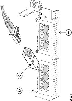
There are two models, each with updated revisions (-B), of the 8-Port Fast Ethernet line card. The two fiber-optic interface versions are functionally equivalent; the -B model contains some newer ASICs and memory chips, however, and requires a later version of Cisco IOS. The copper interface versions are also both functionally equivalent; the -B model contains some newer ASICs and memory chips and requires a later version of Cisco IOS. The front panels are shown in Figure 1.
Figure 1 8-Port Fast Ethernet Line Card
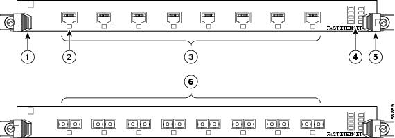
Ejector lever
Alphanumeric LEDs
Status LED (one per port)
Ejector lever
8 RJ-45 copper ports on wire version
8 SC connectors on fiber version
Table 5 summarizes the optics and connectors used by the 8-Port Fast Ethernet line card.
Figure 2 Onboard Receive and Transmit Status LEDs
Note
For more information on the Fast Ethernet interface, cabling, and connectors, see the "Fast Ethernet Interface" section and the "Cabling and Specifications" section.
1-Port Gigabit Ethernet Line Card
The 1-Port Gigabit Ethernet line card provides Cisco 12000 Series Routers with an optical Ethernet interface that operates at a rate of 1 Gbps. The card provides Cisco 12000 Series Routers with a single-port Gigabit Ethernet SC single-mode or multimode connection. The Ethernet optical interface is provided by the GBIC module on the 1-Port Gigabit Ethernet line card.
Figure 3 1-Port Gigabit Ethernet Line Card
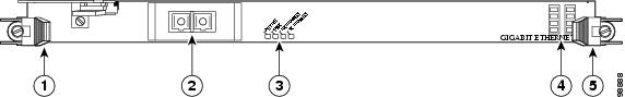
Ejector lever
Alphanumeric LEDs
Gigabit Ethernet port (provided by a GBIC in one line card model)
Ejector lever
Status LEDs
Table 6 summarizes the optics and connectors used by the 1-Port Gigabit Ethernet line card.
Table 6 1-Port Gigabit Ethernet Line Card Optics and Connector Types
GE-SX/LH-SC
See Table 14.
See Table 14.
SC
GE-GBIC-SC-B
See Table 14.
See Table 14.
SC
For more information, refer to the "GBIC Laser Optical Transceiver Modules" section and the "Cabling and Specifications" section.
The default line card route memory configuration is 128 MB; one 128-MB DIMM is installed in the route memory DRAM DIMM0 socket. For more information on memory, see the "Line Card Memory" section.
3-Port Gigabit Ethernet Line Card
The 3-Port Gigabit Ethernet line card provides Cisco 12000 Series Routers with three optical Gigabit Ethernet interfaces on a single line card. These interfaces will provide high-speed connections to other network devices, such as Cisco 12000 Series Routers, other routers, or layer-2 and layer-3 switches that support Gigabit Ethernet interfaces. The 3-Port Gigabit Ethernet line card supports full line rate with two ports in service while the third port is shutdown. With three ports turned on, the 3-Port Gigabit Ethernet line card throughput is limited to the line card forwarding engine limit of 4 million packets per second (4 Mpps) at 64 bytes.
The three ports on the front panel of the line card are port number 0, 1, and 2, from the top of the card to the bottom. Each port consists of a receptacle for a field-replaceable GBIC laser optical transceiver module, which is inserted into the receptacle to provide the Gigabit Ethernet optical interface.
Next to each port on the line card are three green LEDs, aligned vertically and labeled from top to bottom as follows: Link, Active, and RX Frame.
This line card requires a narrow line card slot within the router chassis. Figure 4 shows the line card.
Figure 4 3-Port Gigabit Ethernet Line Card
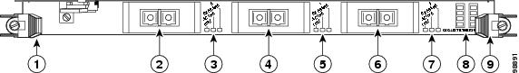
Ejector lever
Port 1 GBIC
Port 2 Status LEDs
Port 0 GBIC
Port 1 status LEDs
Alphanumeric LEDs
Port 0 status LEDs
Port 2 GBIC
Ejector lever
Table 7 3-Port Gigabit Ethernet Line Card Optics and Connector Types
3GE-GBIC-SC
See Table 14.
See Table 14.
SC
Table 7 summarizes the optics and connectors used by the 1-Port Gigabit Ethernet line card.
For more information, refer to the "GBIC Laser Optical Transceiver Modules" section and "Cabling and Specifications" section.
The default line card route memory configuration is 128 MB; one 128-MB DIMM installed in the route memory DRAM DIMM0 socket. For more information on memory, see the "Line Card Memory" section.
4-Port Gigabit Ethernet ISE Line Card
The 4-Port Gigabit Ethernet ISE line card provides Cisco 12000 Series Routers with four optical Gigabit Ethernet interfaces on a single line card, using field replaceable SFP modules. The line card provides high-speed connections to other network devices, such as another Cisco 12000 Series Router, other routers, or layer-2 and layer-3 switches that support Gigabit Ethernet interfaces. The 4-Port Gigabit Ethernet line card throughput is limited to 4 million packets per second (4 Mpps) at 64 bytes, so all four ports cannot run at line rate.
Figure 5 shows the front view of the 4-Port Gigabit Ethernet ISE line card.
Figure 5 4-Port Gigabit Ethernet ISE Line Card

Ejector lever (one at each end)
Alphanumeric LEDs
Status LEDs (one set per port)
Port (provided by SFP module)
Table 8 summarizes the optics and connectors used by the 4-Port Gigabit Ethernet ISE line card.
Table 8 4-Port Gigabit Ethernet ISE Line Card Optics and Connector Types
4GE-SFP-LC
See Table 18.
See Table 18.
LC
For more information, refer to the "Gigabit Ethernet SFP Modules" section and the "Cabling and Specifications" section.
The 4-Port Gigabit Ethernet ISE line card ships with 256 MB of route memory and 512 MB of packet memory. Route memory is field serviceable. For more information on memory, see the "Line Card Memory" section.
10-Port 1-Gigabit Ethernet Line Card
The 10-Port 1-Gigabit Ethernet line card, which is designed for high-density and server-aggregation applications, provides the Cisco 12400 and 12800 Routers with 10 optical 802.3 Gigabit Ethernet interfaces on a single line card. These interfaces provide high-speed connections to other network devices, such as another Cisco 12000 Series Router, other routers, or layer-2 or layer-3 switches that support Gigabit Ethernet interfaces. Figure 6 shows a front view of the line card.
The 10 ports on the front panel of the line card are numbered 0 through 9, from the top of the card to the bottom. Each port consists of a receptacle for a field-replaceable SFP laser optical transceiver module, which is inserted into the receptacle to provide the Gigabit Ethernet optical interface.
Next to each port on the line card are three green LEDs, aligned vertically and labeled from top to bottom as follows: LINK, ACTIVE, and RX FRAME.
Note
Figure 6 10-Port 1-Gigabit Ethernet Line Card
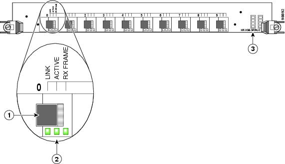
Table 9 summarizes the optics and connectors used by the 10-Port 1-Gigabit Ethernet line card.
Table 9 10-Port 1-Gigabit Ethernet Line Card Optics and Connector Types
10X1GE-SFP-LC,
10X1GE-SFP-LC-BSee Table 18.
See Table 18.
LC
For more information, refer to the "Gigabit Ethernet SFP Modules" section and "Cabling and Specifications" section.
The 10-Port 1-Gigabit Ethernet line card ships with the following memory configurations installed:
•
•
Line card memory on Engine 4 line cards (packet and route memory) is not field replaceable. For more information on memory, see the "Line Card Memory" section.
1-Port 10-Gigabit Ethernet Line Card
The 1-Port 10-Gigabit Ethernet line card provides the supported Cisco 12000 Series Routers with one optical 802.3ae 10-Gigabit Ethernet interface. This interface provides a high-speed connection to other network devices, such as Cisco 12000 Series Routers, or to other routers or layer-2 or layer-3 switches that support 10-Gigabit Ethernet interfaces. Figure 7 shows the front view of the line card.
The port on the front panel of the line card is port number 0. This port uses a hardwired laser optical transceiver to provide a 10-Gigabit Ethernet optical interface. The transceiver consists of two optical interfaces—laser transmit (TX) and laser receive (RX)—that use SC connectors.
Next to the port on the line card are three green LEDs, aligned vertically and labeled from top to bottom as follows: LINK, ACTIVE, and RX FRAME.
Figure 7 1-Port 10-Gigabit Ethernet Line Card

Table 10 summarizes the optics and connectors used by the 1-Port 10-Gigabit Ethernet line card.
For more information, refer to the "10-Gigabit Ethernet" section and the "Cabling and Specifications" section.
The 1-Port 10-Gigabit Ethernet line card ships with 256 MB of route processor memory and 512 MB of packet memory. The memory in the 1-Port 10-Gigabit Ethernet line card is not field replaceable. For more information on memory, see the "Line Card Memory" section.
Modular Gigabit Ethernet Line Card
The Modular Gigabit Ethernet line card, which is designed for high-density and server-aggregation applications, provides the supported Cisco 12000 Series Routers with up to 10 optical 802.3 Gigabit Ethernet interfaces. These interfaces provide high-speed connections to other network devices, such as other Cisco 12000 Series Routers, other types of routers, or layer-2 or layer-3 switches that support Gigabit Ethernet interfaces.
In addition to one hardwired Gigabit Ethernet SFP receptacle, the Modular Gigabit Ethernet line card has three bays in which you can install Ethernet port adapters (EPAs). Each EPA has three receptacles that can be populated with Gigabit Ethernet SFPs, for a total of 10 Gigabit Ethernet ports (one hardwired, plus three on each of the three EPAs). The Ethernet line card ships with 0, 1, 2, or 3 EPAs installed and with at least one SFP module installed.
Next to the port on the line card are three green LEDs, aligned vertically and labeled from top to bottom as follows: LINK, ACTIVE, and RX FRAME.
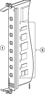
Figure 8 shows a vertical front view of the line card and the backplane connector.
Figure 8 Modular Gigabit Ethernet Line Card

Ejector lever (one on each end)
Hardwired SFP receptacle
5
Status LEDsEPA (three bays)
Alphanumeric LEDs
Table 11 summarizes the optics and connectors used by the Modular Gigabit Ethernet line card.
Table 11 Modular Gigabit Ethernet Line Card Optics and Connector Types
EPA-GE/FE-BBRD,
EPA-3GE-SX/LH-LCSee Table 18.
See Table 18.
LC
For more information, refer to the "Gigabit Ethernet SFP Modules" section and the "Cabling and Specifications" section.
The Ethernet line cards ship with the following memory configurations installed:
•
•
Line card memory on this line card (packet and route memory) is not field replaceable. For more information on memory, see the "Line Card Memory" section.
Preparing for Installation
The following sections provide information about preparing to install line cards:
•
Safety Guidelines
Before you perform any procedure in this publication, review the safety guidelines in this section to avoid injuring yourself or damaging the equipment.
The following guidelines are for your safety and to protect equipment. The guidelines do not include all hazards. Be alert.
Note
•
•
•
Before working with laser optics, read the "Laser Safety" section.
Preventing Electrostatic Discharge
Electrostatic discharge (ESD) damage, which can occur when electronic cards or components are improperly handled, results in complete or intermittent failures. Electromagnetic interference (EMI) shielding is an integral component of the line card. Cisco recommends using an ESD-preventive strap whenever you are handling network equipment or one of its components.
The following are guidelines for preventing ESD damage:
•
•
•
•

Warning
Required Tools and Equipment
You need the following tools and parts to remove and install Ethernet line cards:
•
•
•
•
Note
Refer to the individual line card descriptions in the "Product Overviews" section for more information. Table 4 summarized the hardware requirements for each Ethernet line card.
Removing and Installing a Line Card
The following sections provide procedures for removing or installing a line card:
•
Note
Note
Guidelines for Line Card Removal and Installation
Guidelines for line card removal and installation include the following:
•
Note
•
Caution
After removing and inserting a line card into the same slot, allow at least 60 seconds before removing or inserting another line card.
•
Caution
When you install a line card, always use the ejector levers to ensure that the card is correctly aligned with the backplane connector; the connector pins should make contact with the backplane in the correct order, indicating that the card is fully seated in the backplane. If a card is only partially seated in the backplane, the router will hang and subsequently crash.
For line card configuration information, see the "Configuring and Troubleshooting Line Card Interfaces" section.
Removing a Line Card
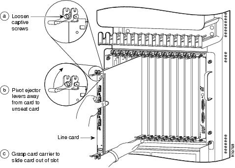
If you are replacing a failed line card, remove the existing line card first, then install the new line card in the same slot. To remove a line card, use Figure 9 as a reference and follow these steps:
Step 1
Step 2
Step 3
Step 4
Figure 9 Line Card Removal and Installation
Caution
Step 5
Step 6
Step 7
Step 8
Step 9
Caution
Note
For information on disconnecting interface cables, see the "Removing and Installing Fiber-Optic Interface Cables" section.
For information on removing the cable-management bracket, see the "Removing a Line Card Cable-Management Bracket" section.
Installing a Line Card
A line card slides into almost any available line card slot and connects directly to the backplane. If you install a new line card, you must first remove the line card blank from the available slot.
Note
Caution
To install a line card, follow these steps:
Step 1
Step 2
Caution
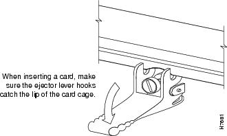
Step 3
Step 4
Figure 10 Ejector Levers
Caution
Step 5
Step 6
Caution
Step 7
Step 8
Step 9
For information on installing cable-management brackets, see the "Installing a Line Card Cable-Management Bracket" section.
For information on installing EPAs, see the "Removing and Installing EPAs" section.
For information on installing GBICs, see the "Removing and Installing GBICs" section.
For information on installing SFP modules, see the "Removing and Installing SFP Modules" section.
For information on installing interface cables, see the "Removing and Installing Fiber-Optic Interface Cables" section.
For information on verifying and troubleshooting the hardware installation, see the "Verifying and Troubleshooting the Installation" section.
Removing and Installing EPAs
The Modular Gigabit Ethernet line card ships with 0, 1, 2, or 3 EPAs installed. If you need to add or change an EPA, follow the procedures in these sections:
•
•
Figure 11 shows an exploded mechanical view of a Gigabit Ethernet EPA with three line card SFP receptacles, an SFP module, and a duplex LC-type cable.
Figure 11 Removing and Replacing EPAs

Removing an EPA from the Modular Gigabit Ethernet Line Card
You can remove an EPA from the Modular Gigabit Ethernet line card with or without the SFP modules installed.
To remove an EPA from your Modular Gigabit Ethernet line card, use Figure 12 as a reference and follow these steps:
Step 1
Step 2
Note which cable connector plug is TX and which is RX for reattachment.
Step 3
Step 4
Step 5
Step 6
Step 7
Caution
Caution
Figure 12 Removing an EPA

If the EPA bay is to remain empty, install an EPA blank (Product Number MAS-EPA-BLANK=) to keep dust out of the line card and to maintain proper airflow and EMI through the line card and chassis.
Inserting an EPA into a Modular Gigabit Ethernet Line Card
To insert an EPA into the Modular Gigabit Ethernet line card, follow these steps:
Warning
Step 1
Figure 13 Locations of Labels and Reference Points on the EPA
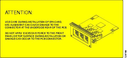
Caution
Step 2
Figure 14 Mating the Connector of the EPA to the Line Card

Figure 15 Side Views - Mating the Connector of the EPA to the Line Card

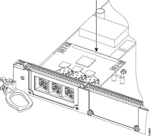
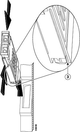
Step 3
Figure 16 Press on the Rear Outer Corners of the EPA
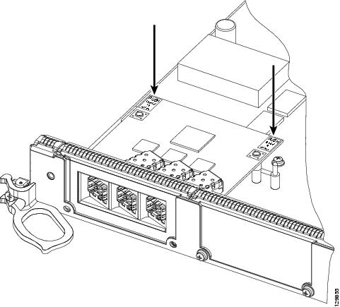
Figure 17 Rear Outer Corners of the EPA (Close-up)
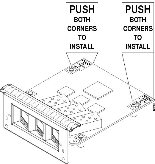
Step 4
Figure 18 Press on the White Labels on the EPA
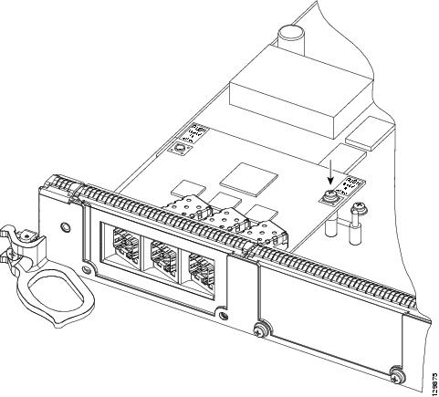
Step 5
Caution
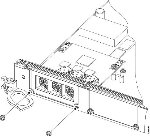
Figure 19 Inserting and Tightening the Screw on the EPA
Step 6
Caution
Figure 20 Inserting the 2 screws on the Faceplate of the Line Card
Removing and Installing GBICs
Your Ethernet line card may have shipped with a GBIC installed. If your line card arrived without the GBIC installed and you need to install it now, or if you need to change your GBIC for another reason, use the procedures in these sections:
•
•
•
Before you remove or install a GBIC, read the installation information in this section and the "Laser Safety" section.
Note
Caution
Caution
Note
General GBIC Handling and Maintenance Guidelines
Follow these GBIC handling and maintenance guidelines:
•
•
•
Removing the GBIC from an Ethernet Line Card
To remove the GBIC from an Ethernet line card, follow these steps:
Step 1
Step 2
Step 3
Figure 21 Removing and Replacing a GBIC
Inserting a GBIC into the Gigabit Ethernet Interface
To insert a GBIC into the Gigabit Ethernet interface, follow these steps:
Step 1
Step 2
Caution
Step 3
Step 4
Step 5
Removing and Installing SFP Modules
Before you remove or install an SFP module, read the installation information in this section and the "Laser Safety" section.
Caution
Caution
Removing and inserting an SFP module can shorten its useful life, so you should not remove and insert SFP modules any more often than is absolutely necessary.
SFP modules use one of four different latching devices to install and remove the module from a port. The four types of SFP module latching devices are described in the following sections:
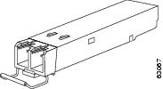
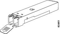
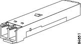
Bale Clasp SFP Module
The bale clasp SFP module has a clasp that you use to remove or install the SFP module. (See Figure 22.)
Figure 22 Bale Clasp SFP Module
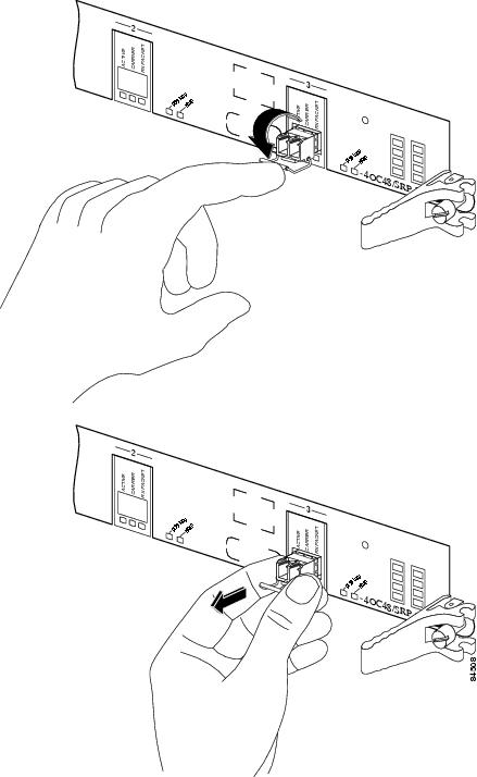
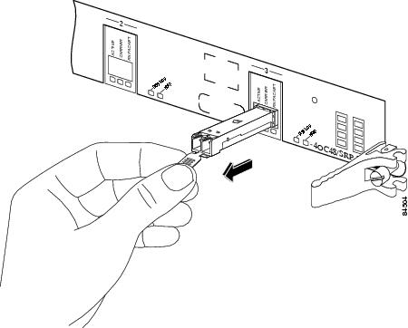
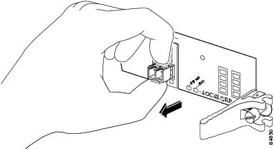
Removing a Bale Clasp SFP Module
To remove this type of SFP module, follow these steps:
Step 1
Step 2
Step 3
Step 4
Figure 23 Removing a Bale Clasp SFP Module
Step 5
Step 6
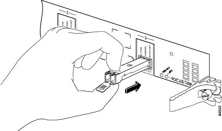
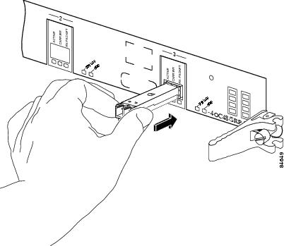
Installing a Bale Clasp SFP Module
To install this type of SFP module, follow these steps:
Step 1
Step 2
Step 3
Figure 24 Installing a Bale Clasp SFP Module into a Port
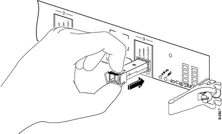
Note
Mylar Tab SFP Module
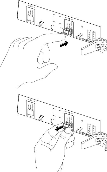
The mylar tab SFP module has a tab that you pull to remove the module from a port. (See Figure 25.)
Figure 25 Mylar Tab SFP Module
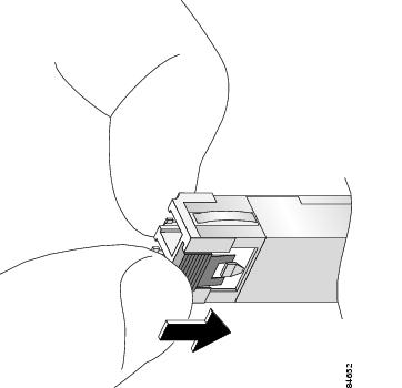
Removing a Mylar Tab SFP Module
To remove this type of SFP module, follow these steps:
Step 1
Step 2
Step 3
Figure 26 Removing a Mylar Tab SFP Module
Step 4
Step 5
Caution
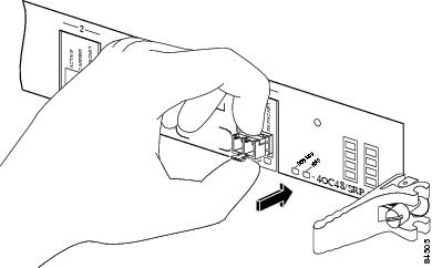
Installing a Mylar Tab SFP Module
To install this type of SFP module, follow these steps:
Step 1
Step 2
Figure 27 Installing a Mylar Tab SFP Module
Note
Actuator Button SFP Module
The actuator button SFP module includes a button that you push in order to remove the SFP module from a port. (See Figure 28.)
Figure 28 Actuator Button SFP Module
Removing an Actuator Button SFP Module
To remove this type of SFP module, follow these steps:
Step 1
Step 2
Step 3
Figure 29 Removing an Actuator Button SFP Module from a Port
Step 4
Step 5
Step 6
Installing an Actuator Button SFP Module
To install this type of SFP module, follow these steps:
Step 1
Step 2
Figure 30 Installing an Actuator Button SFP Module
Note
Slide Tab SFP Module
The slide tab SFP module has a tab underneath the front of the SFP module that you use to disengage the module from a port. (See Figure 31.)
Figure 31 Slide Tab SFP Module
Removing a Slide Tab SFP Module
To remove this type of SFP module, follow these steps:
Step 1
Step 2
Step 3
Step 4
Figure 32 Disengaging the Slide Tab
Step 5
Caution
Figure 33 Removing a Slide Tab SFP Module
Step 6
Step 7
Installing a Slide Tab SFP Module
To install this type of SFP module into a line card, follow these steps:
Step 1
Step 2
Caution
Step 3
Figure 34 Installing a Slide Tab SFP Module
Note
Line Card Cable-Management Bracket
Note
Cisco 12000 Series Routers include a cable-management system that organizes the interface cables entering and exiting the router, keeping them out of the way and free of sharp bends.
Caution
The cable-management system consists of two separate components:
1.
2.
This section describes the line card cable-management bracket. Figure 35 shows the single-port line card cable-management bracket; Figure 36 shows the multiport line card cable-management bracket.
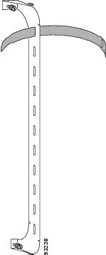
Figure 35 Single-Port Line Card Cable-Management Bracket
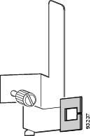
Figure 36 Multiport Line Card Cable-Management Bracket
Note
Caution
Removing and installing the line card cable-management bracket is described in the following procedures:
•
•
Removing a Line Card Cable-Management Bracket
To remove a line card cable-management bracket, follow these steps:
Step 1
Step 2
Step 3
Note
Step 4
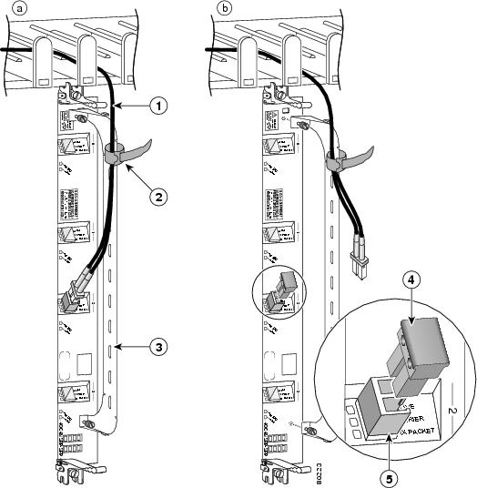
For single-port line card cable-management brackets, carefully remove the interface cable from the cable clip. (See Figure 38.) Avoid any kinks or sharp bends in the cable.
Step 5
Step 6
For single-port line card cable-management brackets, loosen the captive installation screw on the cable-management bracket and remove the bracket from the line card.
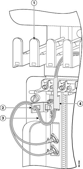
Figure 37 Multiport Line Card Cable-Management Installation and Removal
(4-Port OC-48c/STM-16c DPT Line Card Shown)
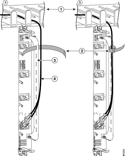
Figure 38 Single-Port Line Card Cable-Management Bracket Installation and Removal (1-Port OC-192c/STM-64c DPT Line Card Shown)
Installing a Line Card Cable-Management Bracket
To install a line card cable-management bracket, follow these steps:
Step 1
Step 2
a.
b.
c.
Step 3
For single-port line card cable-management brackets, carefully press the interface cable onto the cable clip. (See Figure 38.) Avoid any kinks or sharp bends in the cable.
For information on disconnecting and connecting interface cables, see the "Removing and Installing Fiber-Optic Interface Cables" section.
Cabling and Specifications
The following sections provide information about specifications and cabling for Ethernet line cards:
•
•
•
•
Fast Ethernet Interface
The term Ethernet is commonly used for all carrier sense, multiple access/collision detection (CSMA/CD) local-area networks (LANs) that conform to Ethernet specifications, including Fast Ethernet defined by IEEE 802.3u.
IEEE 802.3u specifies the following different physical layers for 100BASE-T:
•
Note
•
Note
•
Note
Table 12 lists the cabling specifications for 100 Mbps Fast Ethernet transmission over UTP, STP, and fiber-optic cables. Table 13 summarizes IEEE 802.3u 100BASE-T physical characteristics for 100BASE-TX and 100BASE-FX.
Table 12 Specification and Connection Limits for 100-Mbps Transmission
Cable specification
Category 3, 4, or 5, 150-ohm UTP or STP, or multimode fiber-optic
62.5/125 multimode fiber-optic
Maximum cable length
-
1.64 ft (0.5 m) (MII-to-MII cable4 )
-
Maximum segment length
328 ft (100 m) for 100BASE-TX
3.28 ft (1 m)5 or 1,312 ft (400 m) for 100BASE-FX
2 km
Maximum network length
656 ft (200 m)5 (with 1 repeater)
-
4 km5 (with 1 repeater)
1 EIA/TIA-568 or EIA-TIA-568 TSB-36 compliant.
2 Cisco Systems does not supply Category 5 UTP RJ-45 or 150-ohm STP MII cables. Both are available commercially.
3 AWG = American Wire Gauge. This gauge is specified by the EIA/TIA-568 standard.
4 This is the cable between the MII port on the FE interface and the appropriate transceiver.
5 This length is specifically between any two stations on a repeated segment.
Table 13 IEEE 802.3u Physical Characteristics
Data rate (Mbps)
100
100
Signaling method
Baseband
Baseband
Maximum segment length (meters)
2 km between repeaters
100 m between DTE1 and repeaters
Media
SC-type: dual simplex or single duplex for receive (RX) and transmit (TX)
RJ-45MII
Topology
Star or hub
Star or hub
1 DTE = data terminal equipment.
Gigabit Ethernet Interface
This section describes the Gigabit Ethernet interface:
•
GBIC Laser Optical Transceiver Modules
The Gigabit Interface Converters (GBICs) are field-replaceable modules that plug into receptacles on the line card and provide the Gigabit Ethernet optical interface. The GBICs have two optical interfaces—laser transmit (TX) and laser receive (RX)—and an electrical interface (to the line card). All GBIC module types have dual SC connectors. Different GBICs can be ordered for each port on the line card. The 1-Port Gigabit Ethernet and 3-Port Gigabit Ethernet line cards use GBICs to provide the Gigabit Ethernet optical interface.
The following sections provide information on the GBIC and Coarse Wave Division Multiplexing (CWDM) GBIC in Ethernet line cards:
•
•
•
GBIC Modules
Fiber-optic transmission specifications identify two types of fiber: single-mode and multimode. Signals can travel farther through single-mode fiber than through multimode fiber.
The 1-Port Gigabit Ethernet and 3-Port Gigabit Ethernet line cards support multimode fiber through the WS-G5484= GBIC laser optical transceiver module and single-mode fiber through the WS-G5486=, WS-G5487=. The 3-Port Gigabit Ethernet line card also supports CWDM-GBIC-xxxx= GBIC laser optical transceiver modules.
Table 14 describes the operating parameters for available GBIC laser optics.
Table 14 Ethernet GBIC Laser Optic Parameters
ConnectorWS-G5484=
SC connectorShortwave (multimode shorthaul)
Defined by 1000BASE-SX standard, IEEE 802.3
850 nm
62.5 micron MMF
902 feet (275 m)
50 micron MMF
1804 feet (550 m)
WS-G5486=
SC connectorLongwave (single-mode longhaul)
Compliant with 1000BASE-LX standard, IEEE 802.3
1310 nm
10/9 micron SMF
6.2 miles (10 km)
WS-G5487=
SC connectorExtended distance (single-mode)
1550 nm
10/9 micron SMF
43.5 miles (70 km)
8 micron SMF2
62 miles (100 km)
CWDM-GBIC-xxxx=3
Longwave (single-mode)
1470-1610 nm4
SMF 10/9 micron
62 miles (100 km)
1 These distances represent best case conditions, depending on fiber quality, dispersion, and losses due to connectors, nodes, or splices. In the case of the CWDM GBICs, CWDM OADM modules or mux/demux modules are needed for these GBICs to work in any topology other than a point-to-point topology within one building, so the maximum distance is determined by an optical power budget calculation that takes into consideration all sources of loss, including the insertion loss due to the CWDM OADM and mux/demux modules, and might be different from the distance shown in the table. For optical parameter information associated with the CWDM OADM and mux/demux modules, see the "Related CWDM Documentation" section.
2 Dispersion-shifted single-mode fiber-optic cable required for 100,000-meter distance.
3 Supported by 3-Port Gigabit Ethernet modules
4 The wavelengths of the CWDM GBICs are based on a 20-nanometer (nm) wavelength grid and are available in eight wavelengths: 1470, 1490, 1510, 1530, 1550, 1570, 1590, and 1610 nm.
Note
Note
The maximum distance for any fiber span in an optical network is determined by the fiber type and quality, as well as the span length, number of splices, and number of optical nodes in the path. If your network design requires the signal to travel close to the theoretical maximum distance (as listed in Table 15), you must calculate the optical power budget and receive (RX) sensitivity for the entire network topology to ensure it is within the specifications of the GBIC option in use.
Note
Table 15 Optical Parameter Values for Calculating Link Power Budget
Power
Power
Sensitivity
BudgetWS-G5484=
-9.5dBm to 0 dBm2
-17 to 0 dBm
-17 dBm
7.5 dB
1,804 feet (550 m)
WS-G5486=
-11 to -3 dBm
-19 to -3 dBm
-19 dBm
8 dB
6.2 miles (10 km)
WS-G5487=
0 to +5 dBm
-23 to 0 dBm
-23 dBm
23 dB
43.5 to 62 miles (70 to 100 km3 )
CWDM-GBIC-xxxx=
+1 to +5 dBm
-31 to -7 dBm
-31 dBm
32 dB
62 miles (100 km)4
1 These distances represent best case conditions, depending on fiber quality, dispersion, and losses due to connectors, nodes, or splices.
2 dBm = decibels referenced to 1 milliwatt.
3 Dispersion-shifted single-mode fiber-optic cable required for 100-km distance.
4 This distance represents best case conditions, depending on fiber quality, dispersion, and losses due to connectors, nodes, or splices. In the case of the CWDM GBICs, CWDM OADM modules or mux/demux modules are needed for these GBICs to work in any topology other than a point-to-point topology within one building, so the maximum distance is determined by an optical power budget calculation that takes into consideration all sources of loss, including the insertion loss due to the CWDM OADM and mux/demux modules, and might be different from the distance shown in the table. For optical parameter information associated with the CWDM OADM and mux/demux modules, see the "Related CWDM Documentation" section.
Using CWDM GBICs with the 3-Port Gigabit Ethernet Line Card
The 3-Port Gigabit Ethernet line card supports CWDM GBICs. The eight CWDM GBICs available for use with an Ethernet line card are active components that plug into standard GBIC receptacles in the line card. They convert Gigabit Ethernet electrical signals into an optical single-mode fiber (SMF) interface that feeds into a CWDM network through a Cisco optical add/drop multiplexing (OADM) plug-in module or multiplexing/demultiplexing (mux/demux) plug-in module. Figure 39 shows the physical appearance of a CWDM GBIC with one optical port dust plug removed.
Figure 39 CWDM GBIC (Yellow-Coded CWDM-GBIC-1550= Shown)
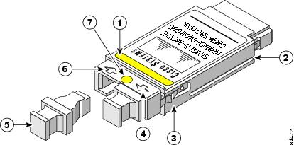
Color band on label
Transmit optical bore
Receive optical bore
Alignment groove
Optical bore dust plug
Color dot
Spring clip
The eight CWDM GBICs available for use with a Gigabit Ethernet line card come in eight wavelengths in a range from 1470 nm to 1610 nm. The color dot between the receive and transmit ports and the color band on the label of the Cisco CWDM GBIC identify the wavelength of the GBIC. Table 16 lists the CWDM GBICs and their associated color codes.
General CWDM GBIC Installation and Usage Guidelines
The Cisco CWDM GBIC solution has two main components: the Cisco CWDM GBICs and the Cisco OADM plug-in modules or mux/demux plug-in modules, which are rack mounted in a Cisco CWDM OADM chassis external to the Cisco 12000 Series Router that contains the Ethernet line card.
The CWDM OADM plug-in modules and mux/demux plug-in modules are passive optical components that multiplex together multiple wavelengths from multiple SMF fiber pairs into one SMF fiber pair. Up to two CWDM plug-in modules can be rack-mounted by using the single-rack-unit CWDM chassis.
The CWDM GBICs plug into the standard GBIC receptacles on the faceplate of the Ethernet line card and are connected to the CWDM OADM or mux/demux plug-in modules in the external CWDM chassis using SMF jumper cables with SC-type connectors.
A Cisco 12000 Series Router equipped with an Ethernet line card and CWDM GBICs can be connected into a CWDM network through external CWDM plug-in modules in the following deployment scenarios:
•
•
•
Related CWDM Documentation
For more information about CWDM GBIC solution deployment, including the optical parameters (insertion loss and isolation values) for the CWDM OADM and mux/demux plug-in modules, see the following related documentation:
•
•
•
General Connection Rules for CWDM GBICs
Observe the following connection rules for CWDM GBICs:
•
Use the CWDM passive optical system connector color codes shown in Table 16 to help you connect your router to the CWDM passive optical system.
•
–
–
•
•
Gigabit Ethernet SFP Modules
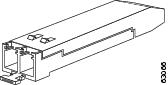
The Gigabit Ethernet laser optical transceiver module is a field-replaceable small form-factor pluggable (SFP) module that plugs into the receptacle on the Ethernet port adapter (EPA) located on the Modular Ethernet line card and provides the Gigabit Ethernet optical interface. (See Figure 40.) The module has two optical interfaces—laser transmit (TX) and laser receive (RX)—and an electrical interface (to the line card). The 4-Port Gigabit Ethernet ISE, 10-Port 1-Gigabit Ethernet, and Modular Gigabit Ethernet line cards use SFP modules.
Figure 40 SFP Module and Fiber-Optic Cable
The following SFP module options are available for a Gigabit Ethernet line card:
•
•
•
•
The SFP modules have LC connectors. Different SFP module options allow you to customize the physical interfaces on the line card by using both types of modules on the same line card. The only restriction is that each port must match the specifications on the other end of the cable (short or long wavelength), and must not exceed the recommended cable length for reliable communication.
Fiber-optic transmission specifications identify two types of fiber: single-mode and multimode. The maximum distance for single-mode installations is determined by the amount of light loss in the fiber path. If your environment requires the light to travel close to the typical maximum distance, you should use an optical time domain reflectometer (OTDR) to measure the power loss.
Table 17 describes the operating parameters for the supported SFP modules.
Table 17 Gigabit Ethernet SFP Module Power Budget and Signal Requirements
Power
PowerGLC-SX-MM
Short wavelength
Multimode,
short haul7.5 dB
-17 to 0 dBm
-17 dBm
984 feet (300 meters)
GLC-LH-SM3
Long wavelength
Single-mode,
long haul8.0 dB
-9.5 to -3 dBm
at 1310 nm-19 to -3 dBm
32,808 feet (10,000 meters)
GLC-LX-SM4
Single-mode,
long-reach8 dB
-11 to -3 dBm
at 1310 nm-19 to -3 dBm
-19 dBm
GLC-ZX-SM5
Single-mode,
extended-reach23 dB
0 to +5 dBm
at 1550 nm-23 to 0 dBm
-23 dBm
1 dBm = decibels referenced to 1 milliwatt
2 nm = nanometer
3 Not valid for 4-Port Gigabit Ethernet ISE line card
4 4-Port Gigabit Ethernet ISE line card only
5 4-Port Gigabit Ethernet ISE line card only
Note
10-Gigabit Ethernet
The 1-Port 10-Gigabit Ethernet line card uses single-mode fiber-optic cable. The maximum distance for single-mode installations is determined by the amount of light loss in the fiber path. If your environment requires the light to travel close to the typical maximum distance (as listed in Table 20), you should use an optical time domain reflectometer (OTDR) to measure the power loss.
The Ethernet line card is offered in two transceiver options:
•
•
Table 19 describes the operating parameters for the transceiver options.
Table 20 lists the power ratings and maximum distances of both models of the Ethernet line cards. The actual distance in any given case depends on the quality of the fiber connected to the transceiver.
Fiber-Optic Interface Cables
Depending on the line card (refer to Table 4), use a single-mode or multimode fiber-optic interface cable with LC-type or SC-type connectors to connect an Ethernet interface on the Ethernet line card in your Cisco 12000 Series Router to another Ethernet interface, router, or switch.
Note
The following types of cables are used with Ethernet line cards to connect your router to another router or switch:
•
•
Note
The following types of cable connectors are used with Ethernet line cards:
•
•
You can use two cables with simplex connectors, or one cable with dual, keyed connectors.
Warning
Figure 41 Simplex SC Cable Connector (Single-mode)
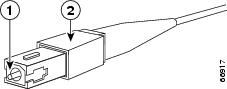
Figure 42 Duplex SC Cable Connector

Figure 43 Simplex LC Cable Connector
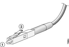
Figure 44 Duplex LC Cable Connector

Note
The connector on the cable might be supplied with a dust cover. If it is, remove the dust cover before trying to connect the cable to the line card port.
Removing and Installing Fiber-Optic Interface Cables
This section contains information on removing and installing fiber-optic interface cables to connect your router to another router or switch.
Note
Removing Fiber-Optic Interface Cables
To remove line card interface cables, refer to Figure 45 (showing one possible arrangement) and follow these steps:
Step 1
Step 2
Warning
Note
Step 3
Step 4
Step 5
Figure 45 Disconnecting Line Card Interface Cables
Installing Fiber-Optic Interface Cables
Use two simplex SC or LC connectors or one duplex SC or LC connector (refer to Figure 46 and Figure 47).
Note
Warning
Warning
Warning
Note
To install a cable, follow these steps:
Step 1
Step 2
Step 3
Step 4
Step 5
Figure 46 Attaching Simplex or Duplex Fiber Cables (SFP Module)

Figure 47 Attaching Simplex or Duplex Fiber Cables (Line Card Port or GBIC)

Note
Cleaning Fiber-Optic Connectors
Fiber-optic connectors are used to connect two fibers together. When these connectors are used in a communication system, proper connection becomes a critical factor. They can be damaged by improper cleaning and connection procedures. Dirty or damaged fiber-optic connectors can result in communication that is inaccurate or not repeatable.
Fiber-optic connectors differ from electrical or microwave connectors. In a fiber-optic system, light is transmitted through an extremely small fiber core. Because fiber cores are often 62.5 microns or less in diameter, and dust particles range from a tenth of a micron to several microns in diameter, dust and any other contamination at the end of the fiber core can degrade the performance of the connector interface where the two cores meet. Therefore, the connector must be precisely aligned and the connector interface must be absolutely free of foreign material.
Connector loss, or insertion loss, is a critical performance characteristic of a fiber-optic connector. Return loss is also an important factor. Return loss specifies the amount of reflected light: the lower the reflection, the better the connection. The best physical contact connectors have return losses of better than -40 dB, but -20 to -30 dB is more common.
The connection quality depends on two factors: the type of connector and the proper cleaning and connection techniques. Dirty fiber connectors are a common source of light loss. Keep the connectors clean at all times, and keep the dust plugs or covers installed when the connectors are not in use.
Before installing any type of cable or connector, use a lint-free alcohol pad from a cleaning kit to clean the ferrule, the protective tube or cone that surrounds the fiber core, and the end-face surface of the fiber core.
As a general rule, any time you detect a significant, unexplained loss of light, clean the connectors. To clean the optical connectors, use a CLETOP fiber optic cleaning cassette (Type A for SC connectors) and follow the manufacturer's usage instructions.
If a CLETOP cleaning cassette is not available, follow these steps:
Step 1
Step 2
Warning
Step 3
Type RJ-45 100BASE-T Copper Cables
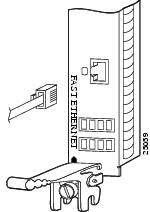
For an 8-Port Fast Ethernet line card with RJ-45 ports, use an EIA/TIA-568-compliant cable with MDI wiring and RJ-45 connectors to connect your Cisco 12000 Series Router to another router or switch. Figure 48 shows a typical RJ-45 connector.
Note
Figure 48 RJ-45 Cable Connector

Removing and Installing RJ-45 100BASE-T Copper Cable
This section contains information on removing and installing RJ-45 copper cables to connect your router to another router or switch.
Removing RJ-45 Cables
To remove line card cables, follow these steps (refer to Figure 49):
Step 1
Step 2
Note
Step 3
Step 4
Installing RJ-45 Cables
Insert the RJ-45 connector into an open port until the connector clicks and locks into place. Attach one cable between each line card interface and the device to which the line card is connected. Figure 49 shows the relationship between the RJ-45 interface on the line card and the cable connector.
Figure 49 Attaching RJ-45 Copper Cables
Verifying and Troubleshooting the Installation
After installing the hardware, you need to look at the LEDs to verify that the Ethernet line card was installed correctly. If it was not, you need to troubleshoot to find the problem. The following sections provide information about how to verify and troubleshoot line card installations:
•
Troubleshooting using Cisco IOS commands is described the "Configuring and Troubleshooting Line Card Interfaces" section.
Initial Boot Process
Note
During a typical line card boot process, the following events occur:
1.
2.
3.
To verify that the line card is working properly, perform the following operational checks:
•
•
If one of these conditions is not met, refer to the "Advanced Line Card Troubleshooting" section to identify any possible problems.
Status LEDs
The Gigabit Ethernet line cards and the 8-Port Fast Ethernet line card have different status LEDs.
Gigabit Ethernet Status LEDs
After installing the line card and connecting the interface cables, verify that the line card is working properly by observing the LEDs on the faceplate. For the locations of the LEDs, refer to the figures in the "Product Overviews" section.
Status LEDs show the status of each fiber-optic connector:
•
•
•
Alphanumeric LEDs explain the state of the line card and are made up of two, four-digit alphanumeric LED displays. (See the "Alphanumeric LEDs" section.)
The status LEDs might not go on until after you have configured the line card interfaces (or turned them on, if they were shut down). In order to verify correct operation of each interface, complete the configuration procedures for the line card. (See the "Configuring and Troubleshooting Line Card Interfaces" section.)
The different operating states of the status LEDs on the Gigabit Ethernet line card are shown in Table 21.
8-Port Fast Ethernet Line Card LEDs
Refer to the figures in the "8-Port Fast Ethernet Line Card" section for the locations of the Link LED and the receive and transmit status LEDs. The Link LED is located on the front panel of the line card. The receive and transmit LEDs are located on the side of the line card and are not visible when a line card is fully installed in the Cisco 12000 Series Router. These LEDs signal the status of the port, as explained in Table 22.
s
The Link LED is on under the following conditions:
•
•
The Link LED is off under the following conditions:
•
•
•
The status LEDs on the line card do not go on until you have configured the line card interfaces (or turned them on if they were shut down). The alphanumeric display does come on when a line card is inserted correctly into the chassis and is powered on.
To verify correct operation of each interface, complete the configuration procedures for the line card (see the "Configuring and Troubleshooting Line Card Interfaces" section).
Alphanumeric LEDs
Ethernet line cards have two four-digit alphanumeric LED displays at one end of the faceplate, near the ejector lever, that display a sequence of messages indicating the state of the card. In general, the LEDs do not turn on until the RP recognizes and powers up the card. As it boots, the line card displays a sequence of messages similar to those in Table 23.
Note
Table 23 Alphanumeric LED Messages During a Typical Initialization Sequence
MROM
nnnnMBus microcode execute; nnnn is the microcode version number.
MBus controller
LMEM
TESTLow memory on the line card is being tested.
Line card ROM monitor
LROM
RUNLow memory test has been completed.
Line card ROM monitor
BSS
INITMain memory is being initialized.
Line card ROM monitor
RST
SAVEContents of the reset reason register are being saved.
Line card ROM monitor
IO
RSTReset I/O register is being accessed.
Line card ROM monitor
EXPT
INITInterrupt handlers are being initialized.
Line card ROM monitor
TLB
INITTLB is being initialized.
Line card ROM monitor
CACH
INITCPU data and instruction cache is being initialized.
Line card ROM monitor
MEM
INITSize of the main memory on the line card is being discovered.
Line card ROM monitor
LROM
RDYROM is ready for the download attempt.
Line card ROM monitor
ROMI
GETROM image is being loaded into line card memory.
RP IOS software
ROM
VGET2ROM image is receiving a response.
RP IOS software
FABI
WAITLine card is waiting for the fabric downloader to load.3
RP IOS software
FABM
WAIT2Line card is waiting for the fabric manager to report that the fabric is usable.
RP IOS software
FABL
DNLDFabric downloader is being loaded into line card memory.
RP IOS software
FABL
STRTFabric downloader is being launched.
RP IOS software
FABL
RUNFabric downloader has been launched and is running.
RP IOS software
IOS
DNLDCisco IOS software is being downloaded into line card memory.
RP IOS software
IOS
FABW2Cisco IOS software is waiting for the fabric to be ready.
RP IOS software
IOS
VGET2Line card is obtaining the Cisco IOS version.
RP IOS software
IOS
RUNLine card is enabled and ready for use.
RP IOS software
IOS
STRTCisco IOS software is being launched.
RP IOS software
IOS
TRANCisco IOS software is transitioning to active.
RP IOS software
IOS
UPCisco IOS software is running.
RP IOS software
1 The entire LED sequence shown in Table 23 might occur too quickly for you to read; therefore, this sequence is provided in this tabular form as a baseline for how a line card should function at startup.
2 This LED sequence only appears in Cisco IOS release 12.0(24)S or later.
3 The fabric downloader loads the Cisco IOS software image onto the line card.
Table 24 lists other messages displayed on the line card alphanumeric LED displays.
Table 24 Other Alphanumeric LED Messages
MAL
FUNCLine card malfunction reported by field diagnostics.
RP
MISM
ATCH1Line card type mismatch in paired slots.
RP
PWR
STRT1Line card has been newly powered on.
RP
PWR
ONLine card is powered on.
RP
IN
RSETIn reset.
RP
RSET
DONEReset complete.
RP
MBUS
DNLDMBus agent downloading.
RP
MBUS
DONEMBus agent download complete.
RP
ROMI
DONEAcquisition of ROM image complete.
RP
MSTR
WAITWaiting for mastership determination.
RP
CLOK
WAITWaiting for slot clock configuration.
RP
CLOK
DONESlot clock configuration done.
RP
FABL
LOADLoading fabric downloader2 complete.
RP
IOS
LOADDownloading of Cisco IOS software is complete.
RP
BMA
ERRCisco IOS software BMA error.
RP
FIA
ERRCisco IOS fabric interface ASIC configuration error.
RP
CARV
ERRBuffer carving failure.
RP
DUMP
REQLine card requesting a core dump.
RP
DUMP
RUNLine card dumping core.
RP
DUMP
DONELine card core dump complete.
RP
DIAG
MODEDiagnostic mode.
RP
DIAG
LOADDownloading field diagnostics over the MBus.
RP
DIAG
F_LDDownloading field diagnostics over the fabric.
RP
DIAG
STRTLaunching field diagnostics.
RP
DIAG
HALTCancel field diagnostics.
RP
DIAG
TESTRunning field diagnostics tests.
RP
DIAG
PASS1Field diagnostics were completed successfully.
RP
POST
STRTLaunching power-on self-test (POST).
RP
UNKN
STATUnknown state.
RP
ADMN
DOWNLine card is administratively down.
RP
SCFG
PRES1Incorrect hw-module slot srp command entered.
RP
SCFG1
REDQRequired hw-module slot srp command not entered.
RP
1 This LED sequence only appears in Cisco IOS release 12.0(24)S or later.
2 The fabric downloader loads the Cisco IOS software image onto the line card.
Troubleshooting the Installation
Note
If the Active LED (Link LED or status LED for line cards with no Active LED) or the alphanumeric display LEDs on a line card do not go on, there is either a problem with the line card installation or a hardware failure. To verify that the line card is installed correctly, follow these steps:
Step 1
Step 2
a.
b.
c.
After the line card reinitializes, the Active LED on the line card should go on. If the Active LED goes on, the installation is complete; if the Active LED does not go on, proceed to the next step.
Step 3
•
•
Step 4
For more information on troubleshooting and diagnostics, refer to the installation and configuration guide that came with your Cisco 12000 Series Router.
Step 5
Note
Configuring and Troubleshooting Line Card Interfaces
After the person who installed the hardware verifies that the new Ethernet line card is installed correctly by examining the LEDs, the network administrator can configure the new interface. The following sections provide information on configuring and troubleshooting the Ethernet line cards:
•
•
•
•
•
Using Configuration Commands
To configure a line card, you enter the correct mode and then enter the commands you need.
First, enter the privileged level of the EXEC command interpreter (privileged EXEC mode) by using the enable command. The system will prompt you for a password if one is set. Next, use the configure command to access configuration mode. If you want to change the default configuration values on the line card, use the configure terminal command to enter global configuration mode. Then, use the interface command to specify the interface and enter interface configuration mode, where you can configure the new interface. Be prepared with the information you will need, such as the interface IP address.
Table 25 lists some configuration commands you may want to use and the default values. Refer to Cisco IOS documentation for complete information about these commands.
A Cisco 12000 Series Router identifies an interface address by its line card slot number and port number, in the format slot/port. The ports on the Ethernet line card are numbered 0, 1, 2, and so on. For example, the slot/port address of the top port on an interface on an Ethernet line card installed in line card slot 1 is 1/0. Even if the line card contains only one port, you must use the slot/port notation.
The Modular Gigabit Ethernet line card identifies an interface address by its line card slot number, EPA number, and port number, in the format slot/EPA_number/port. Table 26 describes the assigned EPA and Gigabit Ethernet port numbers, and how you address a port using Cisco IOS.
For example, to configure gig3, the fourth port on the line card (the first port in the second EPA), you would address slot/1/0. To configure port 9, you would address slot/3/0.
Configuring Ethernet Line Cards
The following procedure is for creating a basic configuration—enabling an interface and specifying IP routing. You might also need to enter other configuration subcommands, depending on the requirements for your system configuration.
To configure an Ethernet line card, you can follow steps like the following:
Step 1
Router> enableIf the system prompts you for a password, enter it.
Step 2
Router# show versionStep 3
Router# show interfaceStep 4
Router# configure terminalStep 5
Router(config)# interface gigabitethernet 1/0You are now in interface configuration mode.
Step 6
Router(config-if)# ip address 10.1.2.3 255.255.255.0Step 7
Router(config-if)# no shutdownThe no shutdown command passes an enable command to the Ethernet line card. It also causes the line card to configure itself based on the most recent configuration commands received by the line card.
Step 8
Router(config-if)# no cdp enableStep 9
Step 10
Step 11
Router# copy running-config startup-configThe system displays an OK message when the configuration has been stored.
After you have completed your configuration, you can check it using show commands, as described in the following sections.
Configuring 802.1Q VLAN Counters
On Cisco 12000 Series Gigabit Ethernet and Fast Ethernet line cards, you can configure 802.1Q VLAN subinterfaces to count VLAN traffic by bytes or packets. By default, VLAN traffic statistics are counted in packets. You cannot enable both byte and packet counters.
To configure the way in which 802.1Q VLAN traffic is counted on an Ethernet subinterface, follow these steps:
Step 1
Router> enableIf the system prompts you for a password, enter it.
Step 2
Router# configure terminalStep 3
Router# interface type slot/port.subinterface-numberStep 4
Router# counter-type {byte | packet}
To display the statistics recorded for 802.1Q VLAN traffic on an Ethernet subinterface, enter the show vlan command in privileged EXEC mode.
Verifying the GBIC Version
You can use the exec slot n show controller gigabitethernet gbic EXEC command to display the GBIC type currently installed in the line card, as shown in the following example:
router# exec slot 4 show controller gigabitethernet 1 gbic========= Line Card (Slot 4) =======** GBIC serial EEPROMidentifier 0x01 (GBIC)connector 0x01 (FibreChannel SC)gbic transceiver_code0x01 1000BASE-SXencoding 0x01 (8B10B)br_nominal (units of 100MHz) 13length_9u (units of 100m) 0length_50u (units of 100m) 50length_62_5u (units of 100m) 22length_cu (unit of 10m) 0vendor_name HEWLETT-PACKARDvendor_oui 0x00 00 00vendor_pn 0x48464252 2D353630 31202020 20202020vendor_rev 0x30303030 0000cc_base 0x74options[0] 0x1A LOS (Loss of Signal) TX Fault TX Disablebr_max (upper baud rate margin, units of %)0br_min (upper baud rate margin, units of %)0vendor_sn 0x39383037 31303037 34383539 36363933date_code 98071000 (yymmddvv, v=vendor specific)Verifying the SFP Version
Use the show interfaces gigabitethernet command to display the SFP module type currently installed in a port on the line card. For example:
Router#show interfaces gigabitethernet 1/0/0GigabitEthernet1/0/0 is administratively down, line protocol is downHardware is GigMac 10 Port GigabitEthernet, address is 0005.5f1a.c8aa (bia0005.5f1a.c8aa)MTU 1500 bytes, BW 1000000 Kbit, DLY 10 usec, rely 255/255, load 1/255Encapsulation ARPA, loopback not setKeepalive set (10 sec)Full-duplex mode, link type is autonegotiation, media type is SXoutput flow-control is unsupported, input flow-control is unsupportedARP type: ARPA, ARP Timeout 04:00:00Last input never, output never, output hang neverLast clearing of "show interface" counters neverQueueing strategy: fifoOutput queue 0/40, 0 drops; input queue 0/75, 0 drops5 minute input rate 0 bits/sec, 0 packets/sec5 minute output rate 0 bits/sec, 0 packets/sec0 packets input, 0 bytes, 0 no bufferReceived 0 broadcasts, 0 runts, 0 giants, 0 throttles0 input errors, 0 CRC, 0 frame, 0 overrun, 0 ignored0 watchdog, 0 multicast, 0 pause input0 packets output, 0 bytes, 0 underruns0 output errors, 0 collisions, 0 interface resets0 babbles, 0 late collision, 0 deferred0 lost carrier, 0 no carrier, 0 pause output0 output buffer failures, 0 output buffers swapped outRouter#Configuration File Examples
This section contains the following examples:
•
Fast Ethernet Example
The following example shows the configuration file commands for an 8-Port Fast Ethernet line card.
!interface FastEthernet10/0ip address 10.1.1.1 255.25x.2x5.0arp timeout 100000no logging event subif-link-statusno keepaliveno cdp enable!interface FastEthernet10/1ip address 10.1.2.1 255.25x.2x5.0no logging event subif-link-statusloopback externalno keepaliveshutdownno cdp enable!interface FastEthernet10/2ip address 10.1.3.1 255.25x.2x5.0no logging event subif-link-statusloopback externalno keepaliveshutdownno cdp enable!interface FastEthernet10/3ip address 10.1.4.1 255.25x.2x5.0no logging event subif-link-statusloopback externalno keepaliveshutdownno cdp enable!interface FastEthernet10/4ip address 10.1.5.1255.25x.2x55.0no logging event subif-link-statusloopback externalno keepaliveshutdownno cdp enable!interface FastEthernet10/5ip address 10.1.6.1 255.25x.2x5.0no logging event subif-link-statusloopback externalno keepaliveno cdp enable!interface FastEthernet10/6ip address 10.1.7.1 255.25x.2x5.0no logging event subif-link-statusloopback externalno keepaliveno cdp enable!interface FastEthernet10/7ip address 10.1.7.1 255.25x.2x5.0no logging event subif-link-statusloopback externalno keepaliveno cdp enable!no ip classlessip route 2x3.2x5.25x.253 25x.25x.2xx.255 Ethernet0ip route 2x3.2x5.25x.253 25x.25x.2xx.255 Ethernet0logging buffered 524288 debugginglogging history size 500logging trap debugging!line con 0exec-timeout 0 0length 33history size 50line aux 0exec-timeout 0 0length 36history size 50line vty 0 4password xyzzylogin!no scheduler max-task-timeendGigabit Ethernet Example
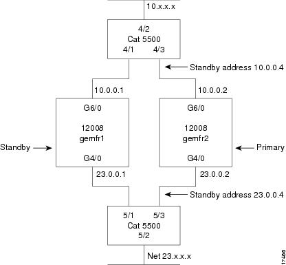
Following are examples of configuration file commands for a Gigabit Ethernet line card used in the scenario shown in Figure 50. A primary and a standby Cisco 12000 Series Router sit between two Cisco Catalyst 5000 series switches. The configuration supports HSRP using ISIS.
Figure 50 HSRP over ISIS using Two Cisco 12000 Series Routers (Topology)
Primary Router Configuration (GE MFR2)
The configuration for the primary router, shown in Figure 50, is as follows:
ip routingno cdp run!no ip domain-lookupline 0history size 30!service timestamps debug datetime msecservice timestamps log datetime msec!router isis area2! NSAP consists of area/ system ID /n-selector! NSAP could be 20 Bytes in length! n-selector is always 1 Byte! if n-selector is zero then NSAP becomes NET! the NSAP is for area 2/system ID 1/n-selector 0net 02.1111.1111.1111.00#NET - Stands for Network Entity Titleis-type level-2-onlyredistribute static!interface Ethernet 0ip address 20.13.5.13 255.255.0.0ip helper-address 223.255.254.254shut!!interface G4/0ip address 23.0.0.2 255.0.0.0mac-addr 0010.1234.2302ip router isis area2no keepaliveno shutdown!!HSRP CONFIGURATIONno ip redirectsstandby 1 priority 200standby 1 ip 23.0.0.4!!This allows the router to become active when its!priority is higher than the others in the same group standby 1 preempt!sets interval between hellos and the hold time for!the standby router to become activestandby 1 timers 3 4!interface G6/0mac-addr 0010.1234.1002ip address 10.0.0.2 255.0.0.0ip router isis area2no keepaliveno shutdown!HSRP CONFIGURATIONno ip redirectsstandby 2 priority 200standby 2 preemptstandby 2 ip 10.0.0.4!This allows the router to become active when its!priority is higher than the others in the same group standby 2 preempt!sets interval between hellos and the hold time for!the standby router to become activestandby 2 timers 3 4Standby Router Configuration (GE MFR1)
The configuration for the standby router, shown in Figure 50, is as follows:
hostname gemfr1ip routingno ip domain-lookupline 0history size 30!service timestamps debug datetime msecservice timestamps log datetime msec!ip host abrick 223.255.254.254router isis area2! NSAP consists of area/ system ID /n-selector! NSAP could be 20 Bytes in length! n-selector is always 1 Byte! if n-selector is zero then NSAP becomes NET! the NSAP is for area2/system ID 2/n-selector 0net 02.2222.2222.2222.00#NET - Stands for Network Entity Titleis-type level-2-onlyredistribute staticnet 02.2222.2222.2222.00is-type level-2-only!interface Ethernet0ip address 20.13.5.12 255.255.255.0ip helper-address 223.255.254.254no keepaliveshutdown!!interface G4/0ip address 23.0.0.1 255.0.0.0mac-address 0010.1234.2301ip router isis area2no keepno shutdown!!HSRP standby configurationno ip redirectsstandby 1 priority 101standby 1 ip 23.0.0.4!This allows the router to become active when its!priority is higher than the others in the same group standby 1 preempt!sets interval between hellos and the hold time for!the standby router to become activestandby 1 timers 3 4!!interface G6/0ip address 10.0.0.1 255.0.0.0mac-address 0010.1234.1001ip router isis area2no keepno shutdown!!HSRP standby configurationno ip redirectsstandby 2 priority 101standby 2 ip 10.0.0.4!This allows the router to become active when its!priority is higher than the others in the same group standby 2 preempt!sets interval between hellos and the hold time for!the standby router to become activestandby 2 timers 3 4!IP and VLAN Configuration for Gigabit Ethernet Example
The following examples show different port configuration file commands for a 10-Port 1-Gigabit Ethernet line card in slot 3 of a system:
•
IP routing
interface gigabitethernet 3/9ip address 172.1.1.1 255.255.255.0mtu 9180VLANs
interface gigabitethernet 3/1.1encapsulation dot1q 10ip address 172.1.1.1 255.255.255.0VLAN counters
interface gigabitethernet 3/1.1counter-type packetIP with source/destination MAC accounting
interface gigabitethernet 3/9ip address 172.1.1.1 255.255.255.0mtu 9180ip accounting mac-address inputip accounting mac-address outputIP with input ACLs
access-list 100 permit ip any anyinterface gigabitethernet 3/9ip address 172.1.1.1 255.255.255.0ip access-group 100 inIP with output ACLs
Extended IP access list 191 permit ip any anyinterface GigabitEthernet1/0ip address 10.10.10.1 255.255.255.0ip access-group 191 outno ip unreachablesno ip directed-broadcastnegotiation autoAdvanced Line Card Troubleshooting
This section provides advanced troubleshooting information in the event of a line card failure. It also provides pointers for identifying whether or not the failure is hardware related. This section does not include any software-related failures, except for those that are often mistaken for hardware failures.
Note
By reading this section and by following the troubleshooting steps, you should be able to determine the nature of the problems you are having with your line card. The first step is to identify the cause of the line card failure or console errors that you are seeing. To discover which card may be at fault, it is essential to collect the output from the following commands:
•
•
•
•
•
Along with these show commands, you should also gather the following information:
•
•
Note
Note
Output Examples
The following are examples of system output that you may see if your Cisco 12000 Series Router line card fails. Key data in the output is underlined.
show context summary Output
Router# show context summaryCRASH INFO SUMMARYSlot 0 : 0 crashesSlot 1 : 1 crashes1 . crash at 10:36:20 UTC Wed Dec 19 2001Slot 2 : 0 crashesSlot 3 : 0 crashesSlot 4 : 0 crashesSlot 5 : 0 crashesSlot 6 : 0 crashes(remainder of output omitted)show logging Output
Router# show loggingSyslog logging: enabled (2 messages dropped, 0 messages rate.limited, 0 flushes,0 overruns)Console logging: level debugging, 24112 messages loggedMonitor logging: level debugging, 0 messages loggedBuffer logging: level debugging, 24411 messages loggedLogging Exception size (4096 bytes)Trap logging: level informational, 24452 message lines logged5d16h: %LCINFO.3.CRASH: Line card in slot 1 crashed5d16h: %GRP.4.RSTSLOT: Resetting the card in the slot: 1,Event: 385d16h: %IPCGRP.3.CMDOP: IPC command 35d16h: %CLNS.5.ADJCHANGE: ISIS: Adjacency to malachim2 (GigabitEthernet1/0) Up,n8 (slot1/0): linecard is disabled.Traceback= 602ABCA8 602AD8B8 602B350C 602B3998 6034312C 60342290 601A2BC4 601A2BB05d16h: %LINK.5.CHANGED: Interface GigabitEthernet1/0, changed state toadministratively down5d16h: %LINEPROTO.5.UPDOWN: Line protocol on Interface GigabitEthernet1/0,changed state to down5d16h: %GRP.3.CARVE_INFO: Setting mtu above 8192 may reduce available bufferson Slot: 1.SLOT 1:00:00:09: %SYS.5.RESTART: System restarted ..(remainder of output omitted)show diag slot Output
Router# show diag 1SLOT 1 (RP/LC 1 ): 3 Port Gigabit EthernetMAIN: type 68, 800.6376.01 rev E0 dev 0HW config: 0x00 SW key: 00.00.00PCA: 73.4775.02 rev E0 ver 2HW version 2.0 S/N CAB0450G8FXMBUS: Embedded AgentTest hist: 0x00 RMA#: 00.00.00 RMA hist: 0x00DIAG: Test count: 0x00000001 Test results: 0x00000000FRU: Linecard/Module: 3GE.GBIC.SC=Route Memory: MEM.GRP/LC.64=Packet Memory: MEM.LC1.PKT.256=L3 Engine: 2 . Backbone OC48 (2.5 Gbps)MBUS Agent Software version 01.46 (RAM) (ROM version is 02.10)Using CAN Bus AROM Monitor version 10.06Fabric Downloader version used 05.01 (ROM version is 05.01)Primary clock is CSC 0 Board is analyzedBoard State is Line Card Enabled (IOS RUN )Insertion time: 00:00:10 (5d16h ago)DRAM size: 67108864 bytesFrFab SDRAM size: 134217728 bytes, SDRAM pagesize: 8192 bytesToFab SDRAM size: 134217728 bytes, SDRAM pagesize: 8192 bytes1 crash since restartshow context slot Output
Router# show context slot 2CRASH INFO: Slot 2, Index 1, Crash at 12:24:22 MET Wed Nov 28 2001VERSION:GS Software (GLC1.LC.M), Version 12.0(18)S1, EARLY DEPLOYMENT RELEASE SOFTWARE (fc1)TAC Support: http://www.cisco.com/tacCompiled Fri 07.Sep.01 20:13 by nmasaCard Type: 3 Port Gigabit Ethernet, S/NSystem exception: SIG=23, code=0x24, context=0x4103FE84System restarted by a Software forced crashSTACK TRACE:.Traceback= 400BEB08 40599554 4004FB64 4005B814 400A1694 400A1680CONTEXT:$0 : 00000000, AT : 41040000, v0 : 00000032, v1 : 4103FC00a0 : 4005B0A4, a1 : 41400A20, a2 : 00000000, a3 : 00000000t0 : 41D75220, t1 : 8000D510, t2 : 00000001, t3 : FFFF00FFt4 : 400C2670, t5 : 00040000, t6 : 00000000, t7 : 4150A398s0 : 0000003C, s1 : 00000036, s2 : 4103C4D0, s3 : 41D7EC60s4 : 00000000, s5 : 00000001, s6 : 41027040, s7 : 00000000t8 : 41A767B8, t9 : 00000000, k0 : 415ACE20, k1 : 400C4260GP : 40F0DD00, SP : 41D7EC48, s8 : 4102D120, ra : 40599554EPC : 0x400BEB08, SREG : 0x3400BF03, Cause : 0x00000024ErrorEPC : 0x400C6698, BadVaddr : 0xFFBFFFFB.Process Traceback= No Extra TracebackSLOT 2:00:00:09: %SYS.5.RESTART: System restarted ..(remainder of output omitted)The type of failure that has occurred in the show context slot 2 example is identified by the underlined SIG= value. The three most common types of line card failures are:
•
•
•
In the example above, the line card has failed and has caused a reload because of a software forced crash exception. Once you have determined the cause and collected the necessary output, you can check for any caveats in your Cisco IOS software release using the Bug Toolkit (available to registered Cisco.com users only).
Checking the Current Status of the Line Card
Once you have determined if the problems are caused by system errors in the log or an actual crash, it is important to check the current status of the line card to see if it has recovered from the failure. The status of individual line cards can be identified either by examining the alphanumeric LEDs located on the front of the line card, or by issuing the show led command.
show led Output
Router# show ledSLOT 1 : RUN IOSSLOT 6 : DNLD FABLSLOT 7 : RP ACTVSLOT 10 : RUN IOSSLOT 11 : RUN IOSSLOT 13 : RUN IOSSLOT 14 : RUN IOS
Note
If the alphanumeric LEDs on the line card display anything other than IOS RUN, or the RP is neither the active Master/Primary nor the Slave/Secondary, there is a problem and the line card has not fully loaded correctly. Before replacing the line card, try fixing the problem by following these steps:
Step 1
Step 2
or
Step 3
Fabric Ping Failure
Fabric ping failures occur when either a line card or the secondary RP fails to respond to a fabric ping request from the primary RP over the switch fabric. Such failures are a problem symptom that should be investigated. They are indicated by the following error messages:
%GRP-3-FABRIC_UNI: Unicast send timed out (1)%GRP-3-COREDUMP: Core dump incident on slot 1, error: Fabric ping failure%LCINFO-3-CRASH: Line card in slot 1 crashedYou can find more information about this issue on Cisco.com in the Troubleshooting Fabric Ping Timeouts and Failures on the Cisco 12000 Series Internet Router publication.
Error Messages
If you receive any error message related to a line card, you can use the Error Message Decoder Tool (on Cisco.com) to find the meaning of this error message. Some errors point to a hardware issue, while others indicate a Cisco IOS software caveat or a hardware issue on another part of the router. This publication does not cover all these messages.
Note
Troubleshooting GBIC Issues
Use the following commands to view the GBIC status on GSR line cards:
LC-Slot2# show controller gigabitethernet 0 gbicOptics disabled or link problems (0x8)*** SFP Serial EEPROM contentsidentifier 0x03 (Reserved)connector 0x07 (Reserved)gbic_transceiver_code 0x01 (1000BASE-SX)encoding 0x01 (8B10B)br_nominal (units of 100MHz)12length_9u (units of 100m)0length_50u (units of 100m)55length_62_5u (units of 100m)27length_cu (unit of 10m)0vendor_name CISCO-AGILENTvendor_oui 0x00 30 D3vendor_pn 0x51464252 2D353739 384C2020 20202020vendor_rev 0x20202020cc_base 0xA0options[0] 0x00br_max (upper baud rate margin, units of %)0br_min (upper baud rate margin, units of %)0vendor_sn 0x41353031 31373633 38202020 20202020date_code 030911 (yymmddvv, v=vendor specific)cc_ext 0x48
Note
Optics disabled or link problems.
Troubleshooting SFP Issues
Use the following steps when troubleshooting an SFP issue:
Step 1
Router# execute-on 1 show techStep 2
# test interfaces gigabitEthernet 1/0Step 3
# debug ethernet-interfaceUse the following command to debug a specific interface in slot 1, port 0:
# debug interface gigabitEthernet 1/0Step 4
LC-Slot3# show controller gigabitethernet 2 1 sfpSFP disabled or link problems (0x32)FPGA Error Messages
If the line card does not boot and you receive an error message indicating that there is a problem with the Field-Programmable Gate Array (FPGA) image (or if the line card alphanumeric LED display remains frozen in IOS STRT state), you need to upgrade the FPGA image using the update-fpga option in the diag command.
Note
When the Cisco IOS image boots, it verifies that a compatible FPGA image is running on the router. The major version number of the FPGA image must be the same as that expected by the Cisco IOS image; the minor version number on the FPGA image must be the same as or greater than the minor version number expected by the Cisco IOS image. For example, if the Cisco IOS image expects a minimum FPGA image of 03.02, the software will verify that the actual major version number of the FPGA image in the line card bootflash is 03, and that the minor version number is 02 or above.
Example error messages indicating an FPGA problem appear as follows:
Error Message    No FPGA image available for slot0. Please run field diagnostics image
on slot0 to upgrade the FPGA image.
Explanation There is currently no valid FPGA image in the bootflash of the line card. You must load a valid FPGA image to the line card bootflash.
Error Message    FPGA image not appropriate or corrupted for slot0. Please run field
diagnostics on slot0 to upgrade the FPGA image.
Explanation The FPGA image currently loaded in the line card bootflash is not compatible with the Cisco IOS software release currently running on the router or is corrupted. Upgrade the FPGA image to the correct version.
Note
Note
Line Card Diagnostics Using Cisco IOS Software Release 12.0(22)S and Later
Note
Line card field diagnostic software is designed to identify any faulty line card within a Cisco 12000 Series Router. Before Cisco IOS Software Release 12.0(22)S, the field diagnostic software was imbedded within the Cisco IOS software. Starting with Cisco IOS Software Release 12.0(22)S, this software is unbundled from the main image and must be downloaded from Cisco.com using the IOS Upgrade Planner.
Cisco initiated this change to accommodate users with 20-MB Flash memory cards. Field diagnostics are now stored and maintained as a separate image under the following name:
c12k-fdiagsbflc-mz-xxx-xx.s (where xxx-xx is the version number)
This image must be available on a separate Flash memory card, Flash disk, or TFTP boot server in order to load line card field diagnostics. The latest version is always available on Cisco.com. RP and fabric tests remain embedded within the main Cisco IOS software image.
While the diagnostic test is running, the line card does not function normally and cannot pass any traffic for the duration of the testing (5 to 20 minutes depending upon the complexity of the line card). Without the verbose keyword, the command provides a truncated output message. When communicating with the Cisco TAC, the verbose mode is helpful in identifying specific problems. The output of the diagnostic test without the verbose command appears like the following example:
Router# diag 7 tftp://223.255.254.254/diagnostic/award/c12k.fdiagsbflc.mz.120-25.sRunning DIAG config checkFabric Download for Field Diags chosen: If timeout occurs, try 'mbus' option.Runnning Diags will halt ALL activity on the requested slot. [confirm]Launching a Field Diagnostic for slot 7Downloading diagnostic tests to slot 7 via fabric (timeout set to 300 sec.)5d20h: %GRP.4.RSTSLOT: Resetting the card in the slot: 7,Event:EV_ADMIN_FDIAGLoading diagnostic/award/c12k.fdiagsbflc.mz.120-25.s from 223.255.254.254(via Ethernet0): !!!!!!!!!!!!!!!!!!!!!!!!!!!!!!!!!!!!!!!!!!!!!!!!!5d20h: Downloading diags from tftp file tftp://223.255.254.254/diagnostic/award/c12k.fdiagsbflc.mz.120-25.s!!!!!!!!!!!!!!!!!!!!!!!!!!!!!!!!!!!!!!!!!!!!!!!![OK . 13976524 bytes]FD 7> *****************************************************FD 7> GSR Field Diagnostics V6.05FD 7> Compiled by award on Tue Jul 30 13:00:41 PDT 2002FD 7> view: award.conn_isp.FieldDiagReleaseFD 7> *****************************************************Executing all diagnostic tests in slot 7(total/indiv. timeout set to 2000/600 sec.)FD 7> BFR_CARD_TYPE_OC12_4P_POS testing...FD 7> Available test types 2FD 7> 1FD 7> Completed f_diags_board_discovery() (0x1)FD 7> Test list selection received: Test ID 1, Device 0FD 7> running in slot 7 (30 tests from test list ID 1)FD 7> Skipping MBUS_FDIAG command from slot 2FD 7> Just into idle stateField Diagnostic ****PASSED**** for slot 7Shutting down diags in slot 7Board will reload(remainder of output omitted)The line card reloads automatically only after passing the test. If the line card fails the test, it will not reload automatically. You can manually reload the line card by using the hw-module slot slot reload command.
Field diagnostic results are stored in an electrically erasable programmable read-only memory (EEPROM) on the line card. It is possible to view the results of the last diagnostic test performed on the line card by executing the diag slot previous command.
There are some caveats that exist that cause diagnostic tests to fail, even though the line card is not faulty. As a precaution, if the line card fails and had been replaced previously, you should review this output with the Cisco TAC.
Line Card Diagnostics Using Cisco IOS Software Releases Prior to 12.0(22)S
Note
Line card field diagnostic software is bundled with the main Cisco IOS software to enable you to test whether a suspect line card is faulty. To use this feature, you must be in privileged enable mode, and issue the diag slot [verbose] command.
While the diagnostic test is running, the line card does not function normally and cannot pass any traffic for the duration of the testing. Without the verbose keyword, the command provides a truncated output message. When communicating with the Cisco TAC, the verbose mode is helpful in identifying specific problems. The output of the diagnostic test without the verbose command appears like the following example:
Router#diag 3Running DIAG config checkRunning Diags will halt ALL activity on the requested slot[confirm]Router#Launching a Field Diagnostic for slot 3Downloading diagnostic tests to slot 3 (timeout set to 600 sec.)*Nov 18 22:20:40.237: %LINK.5.CHANGED: Interface GigabitEthernet3/0,changed state to administratively downField Diag download COMPLETE for slot 3FD 3> *****************************************************FD 3> GSR Field Diagnostics V4.0FD 3> Compiled by award on Thu May 18 13:43:04 PDT 2000FD 3> view: award.conn_isp.FieldDiagReleaseFD 3> *****************************************************FD 3> BFR_CARD_TYPE_1P_GE testing...FD 3> running in slot 3 (83 tests)Executing all diagnostic tests in slot 3(total/indiv. timeout set to 600/200 sec.)Field Diagnostic: ****TEST FAILURE**** slot 3: last test run 51,Fabric Packet Loopback, error 3Shutting down diags in slot 3slot 3 done, will not reload automaticallyThe line card reloads automatically only after passing the test. In the example above, the line card failed the test and did not reload automatically. You can manually reload the line card by using the hw-module slot slot reload command.
Field diagnostic results are stored in an EEPROM on the line card. It is possible to view the results of the last diagnostic test performed on the line card by executing the diag slot previous command.
There are some caveats that exist that cause diagnostic tests to fail, even though the line card is not faulty. As a precaution, if the line card fails and had been replaced previously, you should review this output with the Cisco TAC.
Line Card Memory
This section contains information about the following:
•
You can replace the route memory on Ethernet line cards. Route memory modules are installed into 144-pin small-outline DIMM (SODIMM) sockets. Route memory runs the Cisco IOS software image and stores the updated network routing tables downloaded from the route processor.
Table 27 provides information about the various hardware engines available with the Ethernet line cards. The engine determines where the memory is placed.
Line Card Memory Locations
The following sections contain general line card memory information for each Ethernet line card:
•
•
•
•
•
•
Memory removal and installation instructions are found in the "Removing and Installing Line Card Memory" section.
Engine 0 and Engine 1 Line Card Memory Locations
Figure 51 shows the dual in-line memory module (DIMM) socket locations on an Engine 0 or Engine 1 line card. This line card is equipped with six DIMM sockets:
•
•
Figure 51 Engine 0 and Engine 1 Line Card Memory Locations
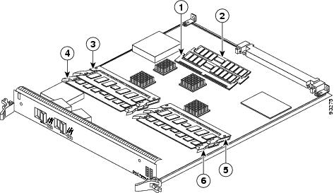
Route memory DIMM0
Packet memory RX DIMM1
Route memory DIMM1
Packet memory TX DIMM0
Packet memory RX DIMM0
Packet memory TX DIMM1
Engine 2 Line Card Memory Locations
Figure 52 shows the DIMM socket locations on an Engine 2 line card. This line card is equipped with eight DIMM sockets:
•
•
•
•
Figure 52 Engine 2 Line Card Memory Locations
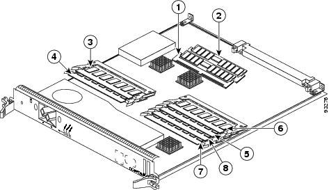
ISE Line Card Memory Locations
Figure 53 shows the small outline DIMM (SODIMM) socket locations on an ISE line card. This line card is equipped with 10 SODIMM sockets:
•
•
•
Figure 53 ISE Line Card Memory Locations
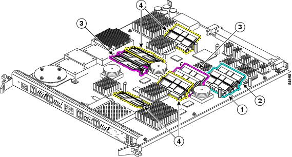
Route memory SODIMM0
Four packet memory SODIMM sockets (not field serviceable)
Route memory SODIMM1
Four TLU/PLU memory SODIMM sockets (not field serviceable)
There are two route memory sockets on ISE (Engine 3) line cards that support the addition of route memory modules. Table 28 describes the various memory upgrade options.
Table 28 ISE/Engine 3 Line Card Memory Upgrade Options
4-Port Gigabit Ethernet
•
•
•
•
•
•
•
1 If you need to upgrade beyond 2 x 512 MB modules you must contact the Cisco Technical Assistance Center (TAC) for instructions.
2 Do not mix memory sizes. Both DIMMs must be the same size memory.
3 Requires Cisco IOS Release 12.0(31)S or later, and you must upgrade the route processor ROMMON code to Version 1.13 or later before installing the upgraded memory.
Engine 4 Line Card Memory Locations
Figure 54 shows the DIMM socket locations on an Engine 4 line card. These line cards are equipped with five DIMM sockets:
•
•
The route memory module is installed to a 144-pin SODIMM socket. Route memory runs the Cisco IOS software image and stores the updated network routing tables downloaded from the route processor.
Figure 54 Engine 4 Line Card Memory Locations
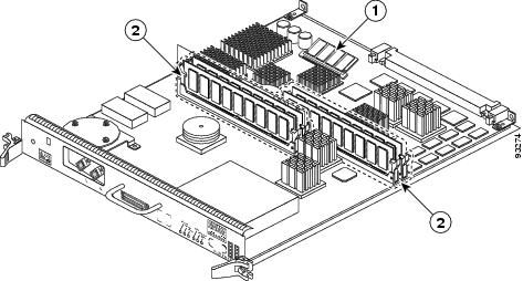
Ethernet Line Card Route Memory Options
Route memory runs the Cisco IOS software image and stores updated network routing tables downloaded from the route processor (RP). Line card route memory ranges from 128 MB to 256 MB. Table 29 lists the available route memory configurations and associated product numbers of the memory modules used for upgrading route memory on Ethernet line cards.
Table 29 Route Memory Configurations for Ethernet Line Cards
64 MB
MEM-GRP/LC-64=1
1 64-MB DIMM
DIMM0 or DIMM1
128 MB
MEM-DFT-GRP/LC-128
1 128-MB DIMM
DIMM0 or DIMM1
128 MB
MEM-GRP/LC-128=
1 128-MB DIMM
DIMM0 or DIMM1
256 MB
MEM-GRP/LC-256=
2 128-MB DIMMs
DIMM0 and DIMM1
256 MB
MEM-LC4-256=2
1 256-MB SODIMM
Varies
1 This option adds a second 64-MB DIMM for a total of 128 MB for line cards that are equipped with 64 MB.
2 This option is only compatible with the 4-Port Ethernet line cards and is for replacement only.
If you are upgrading or replacing line card route and packet memory, refer to the Cisco 12000 Series Router Memory Replacement Instructions publication for installation procedures and the most up-to-date memory options.
Ethernet Line Card Packet Memory Options
Line card packet memory temporarily stores data packets awaiting switching decisions by the line card processor. Once the line card processor makes the switching decisions, the packets are propagated into the router switch fabric for transmission to the appropriate line card.
Table 30 lists the packet memory options for Ethernet line cards.
Table 30 Ethernet Line Card Packet Memory Options
256 MB
MEM-LC1-PKT-256=
2 RX 64-MB DIMMs
2 TX 64-MB DIMMsRX DIMM0 and RX DIMM1
TX DIMM0 and TX DIMM1
512 MB (upgrade)
MEM-PKT-512-UPG=
2 RX 128-MB DIMMs
2 TX 128-MB DIMMsRX DIMM0 and RX DIMM1
TX DIMM0 and TX DIMM1
1 The SDRAM DIMMs installed in a given buffer (either receive or transmit) must be the same type and size, but the individual receive and transmit buffers can operate with different memory capacities.
Removing and Installing Line Card Memory
Before beginning the memory replacement procedures in this section, ensure that you have the proper tools and equipment at hand, and that you are using appropriate ESD-prevention equipment and techniques. Before removing or installing memory, observe the following guidelines:
•
–
–
–
•
–
–
–
–
Instructions are in the following sections:
•
Removing a DIMM
To remove a DIMM from a line card, follow these steps:
Step 1
Step 2
Step 3
Note
Figure 55 DIMM Socket with Dual Release Levers
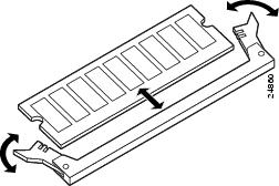
Figure 56 DIMM Socket with Single Release Lever
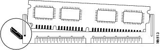
Step 4
•
or
•
Caution
Step 5
Step 6
Step 7
Installing a DIMM
This section contains instructions for installing DIMM memory into a line card.
Note
To install DIMMs in a line card, follow these steps:
Step 1
Step 2
Caution
Step 3
Step 4
Step 5
If necessary, rock the DIMM back and forth gently to align it in the socket.
Figure 57 Handling a DIMM
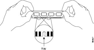
Caution
Step 6
Step 7
If the module appears misaligned, carefully remove it and reseat it, ensuring that the release lever is flush against the side of the DIMM socket.
Step 8
Removing a SODIMM
To remove a SODIMM, follow these steps:
Step 1
Step 2
Step 3
Step 4
Note
Caution
Figure 58 Remove Retaining Clip from Memory Module Socket
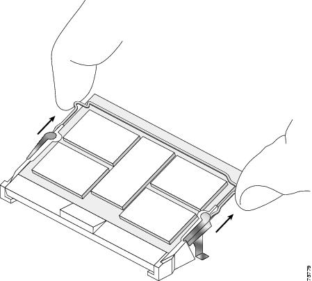
Step 5
Caution
Caution
Figure 59 Moving the Plastic Latch Away from the SODIMM
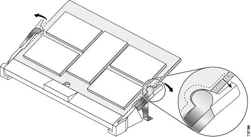
Step 6
Figure 60 Removing a 144-pin SODIMM Module
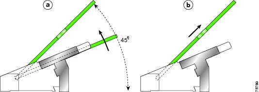
Step 7
Installing a SODIMM
To install a SODIMM module, follow these steps:
Step 1
Step 2
Step 3
Note
Figure 61 SODIMM Socket Retaining Clip

Caution
Step 4
Step 5
Caution
Step 6
Figure 62 SODIMM with Key in Face-Up Position
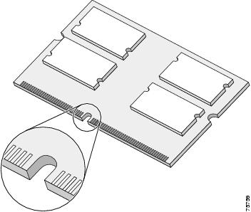
Step 7
Note
Step 8
Be sure your index fingers are located on the outer corners of the SODIMM to maintain even pressure when the module is being seated in the socket.
Figure 63 Inserting a 144-pin SODIMM Module
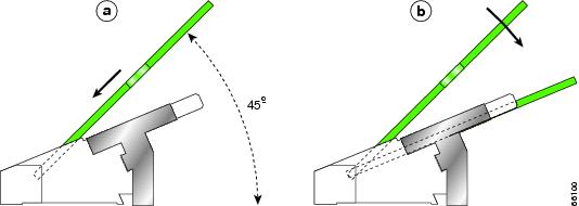
Step 9
Caution
Step 10
Step 11
Step 12
(See Figure 64.)Figure 64 Inserting the Retaining Clip
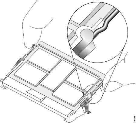
The clip is properly installed when the clip detente protrudes below the strain relief and plastic latch. (See Figure 65.)
Figure 65 Retaining Clip Completely Installed into Module Latch
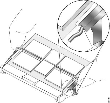
Checking the Installation of Line Card Memory
After you install line card memory and reinstall the line card in the router, the router reinitializes the line card and detects the memory change as part of the reinitialization cycle. The time required for the router to initialize can vary with different router configurations and memory configurations.
If the line card does not reinitialize properly after you upgrade memory, or if the console terminal displays a checksum or memory error, verify that you installed the correct DIMMs and that they are installed correctly on the line card.
To check the installation of line card memory, follow these steps:
Step 1
Step 2
Step 3
If the router fails to restart properly after several attempts and you are unable to resolve the problem, access Cisco.com or contact your Cisco service representative for assistance. Before calling, however, make note of any console error messages, unusual LED states, or other router indications or behaviors that might help to resolve the problem.
Regulatory, Compliance, and Safety Information
This section includes regulatory, compliance, and safety information in the following sections:
•
•
Translated Safety Warnings and Agency Approvals
The complete list of translated safety warnings and agency approvals is available in the Regulatory Compliance and Safety Information for Cisco 12000 Series Internet Routers publication.
(Document Number 78-4347-xx.)Electromagnetic Compatibility Regulatory Statements
This section contains the following information:
•
•
FCC Class A Compliance
This equipment has been tested and found to comply with the limits for a Class A digital device, pursuant to part 15 of the FCC rules. These limits are designed to provide reasonable protection against harmful interference when the equipment is operated in a commercial environment. This equipment generates, uses, and can radiate radio-frequency energy and, if not installed and used in accordance with the instruction manual, may cause harmful interference to radio communications. Operation of this equipment in a residential area is likely to cause harmful interference, in which case users will be required to correct the interference at their own expense.
Modifying the equipment without Cisco's authorization may result in the equipment no longer complying with FCC requirements for Class A digital devices. In that event, your right to use the equipment may be limited by FCC regulation and you may be required to correct any interference to radio or television communication at your own expense.
You can determine whether your equipment is causing interference by turning it off. If the interference stops, it was probably caused by the Cisco equipment or one of its peripheral devices. If the equipment causes interference to radio or television reception, try to correct the interference by using one or more of the following measures:
•
•
•
•
CISPR 22
This apparatus complies with CISPR 22/EN55022 Class B radiated and conducted emissions requirements.
Canada
English Statement of Compliance
This class A digital apparatus complies with Canadian ICES-003.
French Statement of Compliance
Cet appareil numérique de la classe A est conforme à la norme NMB-003 du Canada.
Europe (EU)
This apparatus complies with EN55022 Class B and EN55024 standards when used as ITE/TTE equipment, and EN300386 for Telecommunications Network Equipment (TNE) in both installation environments, telecommunication centers and other indoor locations.
Class A Notice for Hungary
Class A Notice for Taiwan and Other Traditional Chinese Markets
VCCI Class A Notice for Japan
Class A Notice for Korea
Laser Safety
Single-mode Ethernet line cards (all of the line cards except 8-Port Fast Ethernet) are equipped with a Class 1 laser. Multimode Ethernet line cards (Gigabit Ethernet and 4-Port Gigabit Ethernet ISE) are equipped with a Class 1 LED. These devices emit invisible radiation. Do not stare into operational line card ports. The following laser warnings apply to the Ethernet line cards:
•
•
Class 1 Laser Product Warning (Single-mode)
Warning
Class 1 LED Product Warning (Multimode)
Warning
General Laser Warning
Warning
For translated safety warnings, refer to the Regulatory Compliance and Safety Information for
Cisco 12000 Series Internet Routers publication (Document Number 78-4347-xx).Obtaining Documentation
Cisco documentation and additional literature are available on Cisco.com. Cisco also provides several ways to obtain technical assistance and other technical resources. These sections explain how to obtain technical information from Cisco Systems.
Cisco.com
You can access the most current Cisco documentation on the World Wide Web at this URL:
http://www.cisco.com/univercd/home/home.htm
You can access the Cisco website at this URL:
International Cisco websites can be accessed from this URL:
http://www.cisco.com/public/countries_languages.shtml
Ordering Documentation
You can find instructions for ordering documentation at this URL:
http://www.cisco.com/univercd/cc/td/doc/es_inpck/pdi.htm
You can order Cisco documentation in these ways:
•
http://www.cisco.com/en/US/partner/ordering/index.shtml
•
Documentation Feedback
You can submit e-mail comments about technical documentation to bug-doc@cisco.com.
You can submit comments by using the response card (if present) behind the front cover of your document or by writing to the following address:
Cisco Systems
Attn: Customer Document Ordering
170 West Tasman Drive
San Jose, CA 95134-9883We appreciate your comments.
Obtaining Technical Assistance
For all customers, partners, resellers, and distributors who hold valid Cisco service contracts, the Cisco Technical Assistance Center (TAC) provides 24-hour-a-day, award-winning technical support services, online and over the phone. Cisco.com features the Cisco TAC website as an online starting point for technical assistance. If you do not hold a valid Cisco service contract, please contact your reseller.
Cisco TAC Website
The Cisco TAC website provides online documents and tools for troubleshooting and resolving technical issues with Cisco products and technologies. The Cisco TAC website is available 24 hours a day, 365 days a year. The Cisco TAC website is located at this URL:
Accessing all the tools on the Cisco TAC website requires a Cisco.com user ID and password. If you have a valid service contract but do not have a login ID or password, register at this URL:
http://tools.cisco.com/RPF/register/register.do
Opening a TAC Case
Using the online TAC Case Open Tool is the fastest way to open P3 and P4 cases. (P3 and P4 cases are those in which your network is minimally impaired or for which you require product information.) After you describe your situation, the TAC Case Open Tool automatically recommends resources for an immediate solution. If your issue is not resolved using the recommended resources, your case will be assigned to a Cisco TAC engineer. The online TAC Case Open Tool is located at this URL:
http://www.cisco.com/tac/caseopen
For P1 or P2 cases (P1 and P2 cases are those in which your production network is down or severely degraded) or if you do not have Internet access, contact Cisco TAC by telephone. Cisco TAC engineers are assigned immediately to P1 and P2 cases to help keep your business operations running smoothly.
To open a case by telephone, use one of the following numbers:
Asia-Pacific: +61 2 8446 7411 (Australia: 1 800 805 227)
EMEA: +32 2 704 55 55
USA: 1 800 553-2447For a complete listing of Cisco TAC contacts, go to this URL:
http://www.cisco.com/warp/public/687/Directory/DirTAC.shtml
TAC Case Priority Definitions
To ensure that all cases are reported in a standard format, Cisco has established case priority definitions.
Priority 1 (P1)—Your network is "down" or there is a critical impact to your business operations. You and Cisco will commit all necessary resources around the clock to resolve the situation.
Priority 2 (P2)—Operation of an existing network is severely degraded, or significant aspects of your business operation are negatively affected by inadequate performance of Cisco products. You and Cisco will commit full-time resources during normal business hours to resolve the situation.
Priority 3 (P3)—Operational performance of your network is impaired, but most business operations remain functional. You and Cisco will commit resources during normal business hours to restore service to satisfactory levels.
Priority 4 (P4)—You require information or assistance with Cisco product capabilities, installation, or configuration. There is little or no effect on your business operations.
Obtaining Additional Publications and Information
Information about Cisco products, technologies, and network solutions is available from various online and printed sources.
•
http://www.cisco.com/go/marketplace/
•
http://cisco.com/univercd/cc/td/doc/pcat/
•
•
•
http://www.cisco.com/go/iqmagazine
•
•
http://www.cisco.com/en/US/learning/index.html
This document is to be used in conjunction with the installation and configuration guide for your Cisco 12000 Series Router.

Copyright © 2005 Cisco Systems, Inc. All rights reserved.


 Feedback
Contact Cisco
- Open a Support Case

- (Requires a Cisco Service Contract)