

Cisco Success Tracks
Make the most of your IT investment
Optimize the value of your routing solutions for faster results, with digital insights and services expertise.
Deploy an intelligent, self-defending network with a NetSecOPEN certified platform for network security (SD-WAN) performance.
Secure users and data with our SASE-ready platform. Boost security from the WAN to the cloud with trusted authentication, robust encryption, granular segmentation, and integrated next-generation firewall (NGFW) capabilities.
Fast-track deployment with one-click automation. Deploy integrated network services on demand—anywhere, anytime—with simplified configuration and management.
Get in-depth analytics, visibility, and control to make excellent application experience a cornerstone of your operations.
Improve efficacy and reduce human errors by combining the built-in NGFW in routers with all other Cisco security technologies in Cisco Security Cloud Control.
Optimized for data centers with security, scale, and performance to support critical applications.
Throughput, threat protection, and seamless integration for enterprises, large branches, and campuses.
For campuses and large branches: high throughput, native assurance, and post-quantum cryptography.
A network edge with fast aggregation, multicloud networking, security, scale, and intelligence.
Securely connect remote industrial operations with this rugged, compact, and modular SD-WAN-enabled router.
Security at the industrial edge with a next-generation firewall for stationary or moving assets.
Unite your outdoor edge with this IP67-rated, SD-WAN-enabled, fully modular router.
Deliver industrial networking and SD-WAN performance with rugged all-in-one routing and switching.
Deliver the performance and scale to build the internet of the future with cloud-enhanced systems.
Scale with high-density 400G routers for long-term growth and segment routing for SLA-based services.
Support the application performance required to power your services with scalable routing systems.
Simplify your access network and converge services with these secure and programmable routers.
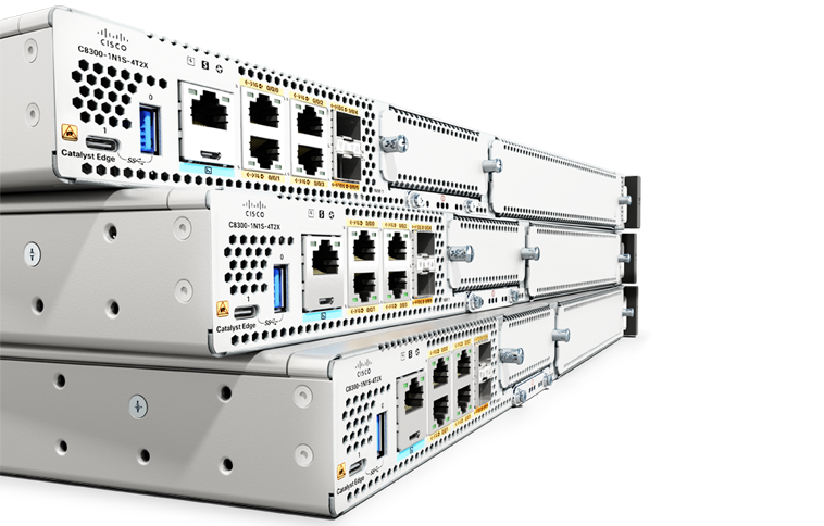
Security, advanced performance, and flexible management for medium branches.
For small branches, the compact, fanless 8100 Series has enterprise-grade security and high performance.
Boost performance with advanced security, multicloud access, and wireless capability—in one device.
Streamline your small business with secure SD-WAN, access, and IoT on a cloud-first platform.
Combine WAN, switching, security, and advanced connectivity options in a compact, fanless platform.
Experience reliable connectivity with enterprise Wi-Fi access at home without the need for a VPN.
Secure, cloud-managed teleworker gateways with Wi-Fi 6 and optional cellular failover.
For small branches, the compact, fanless 8100 Series has enterprise-grade security and high performance.
Robust, reliable connectivity for branch and campus networks
Optimize applications and enhance user experience with secure, multicloud connectivity.
Securely extend SD-WAN to public and private cloud environments in three clicks.