Installing the Cisco ONS 15216-MD-48-CM Interleaver and Deinterleaver Pluggable and Cisco ONS 15216-MD-48-CME Coupler and Splitter Pluggable
Available Languages
Contents
- Installing the Cisco ONS 15216-MD-48-CM Interleaver and Deinterleaver Pluggable and the Cisco ONS 15216-MD-48-CME Coupler and Splitter Pluggable
- Overview of the Cisco ONS 15216-MD-48-CM and ONS 15216-MD-48-CME Pluggables
- Features
- Functional Description
- Optical Interconnections
- Channel Wavelength Allocation
- Port Label Description
- Channel Identification Label
- Safety Information
- Laser Radiation Emission Restrictions
- Electrical Safety
- Unpacking and Verifying the ONS 15216-MD-48-CM/15216-MD-48-CME Pluggable
- Installing the ONS 15216-MD-48-CM/15216-MD-48-CME Pluggable
- Install and Route Fiber-Optic and USB Cables
- Uninstalling the ONS 15216-MD-48-CM/15216-MD-48-CME Pluggable
- Cleaning and Maintaining Fiber-Optic Connectors
- Customer-supplied Cleaning Materials
- Cleaning the Optical Mating Adapter
- Cleaning Fiber-Optic Cable Connectors
- Cisco ONS 15216-MD-48-CM/15216-MD-48-CME Pluggable Specifications
- Environmental and Power Specifications
- Optical Specifications
- Connector and Mechanical Specifications
- Related Documentation
- Obtaining Documentation and Submitting a Service Request
Installing the Cisco ONS 15216-MD-48-CM Interleaver and Deinterleaver Pluggable and the Cisco ONS 15216-MD-48-CME Coupler and Splitter Pluggable
This document explains how to install and operate the Cisco ONS 15216-MD-48-CM interleaver and deinterleaver pluggable and the Cisco ONS 15216-MD-48-CME coupler and splitter pluggable.
Overview of the Cisco ONS 15216-MD-48-CM and ONS 15216-MD-48-CME Pluggables
The Cisco ONS15216-MD-48-CM is 50 GHz/100 GHz C-band interleaver and deinterleaver pluggable that provides signal interleaving and deinterleaving in 50-GHz channel spacing DWDM systems. It operates inside the ONS 15216-MD-40, ONS 15216-EF-40, or ONS 15216-MD-48 odd and even patch panels.
The Cisco ONS15216-MD-48-CME is a bidirectional unit that has the MUX and the DEMUX functions implemented as two different sections. The DEMUX section includes an optical splitter to split the optical signal evenly into two different output ports: EVEN-TX port and ODD-TX port. The optical coupler provides the MUX section and combines even and odd channels signals at 100 GHz spacing (EVEN-RX and ODD-RX ports respectively) into a signal of 50 GHz channel spacing.
For installing the 15216-MD-40 patch panel, refer to the "Installing the Cisco ONS 15216-MD-40-ODD and 15216-MD-40-EVEN Mux/Demux Patch Panels" guide. For installing the 15216-EF-40 patch panel, refer to the "Installing the Cisco ONS 15216-EF-40-ODD and 15216-EF-40-EVEN Mux/Demux Patch Panels" guide. For installing the 15216-MD-48 patch panel, refer to the "Installing the Cisco ONS 15216-MD-48-ODD and 15216-MD-48-EVEN Mux/Demux Patch Panels"
The ONS 15216-MD-48-CM/15216-MD-48-CME interfaces between the following:
The advantages of installing the ONS15216-MD-48-CM/15216-MD-48-CME are:
Features
The ONS 15216-MD-48-CM/15216-MD-48-CME is optically and electrically passive and requires no temperature control. It uses fused fiber coupler and birefringent crystal technologies.
Functional Description
ONS 15216-MD-48-CM Interleaver and Deinterleaver Pluggable
The ONS 15216-MD-48-CM pluggable increases the network capacity by combining two optical data streams into a single, more densely spaced stream. This pluggable can be used in mux mode to combine two 100 GHz optical signal streams into one 50 GHz stream, or in demux mode to separate the 50 GHz stream into two 100 GHz streams.
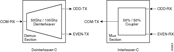
The ONS 15216-MD-48-CM is a bidirectional pluggable in which the mux and demux functions are implemented in two different sections to enable signals flowing in opposite directions to be managed separately. This functionality is illustrated in the following figure.
The interleaver (3dB optical coupler) in the mux section combines the even and odd channel signals at 100 GHz spacing (EVEN-RX and ODD-RX ports, respectively) into the 50 GHz channel spacing signal.
The deinterleaver in the demux section separates the 50 GHz channel spacing signal into even and odd channel signals of 100 GHz spacing (EVEN-TX and ODD-TX ports, respectively).
The interleaver and deinterleaver module is plugged inside the patch panel and is interconnected with another patch panel of a different grid (odd or even).
ONS 15216-MD-48-CME Coupler and Splitter Pluggable
The ONS 15216-MD-48-CME pluggable increases the network capacity by combining two optical data streams into a single, more densely spaced stream. This pluggable can be used in mux mode to combine two 100 GHz optical signal streams into one 50 GHz stream, or in demux mode to split the optical signal evenly into two different streams.
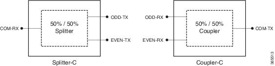
The ONS 15216-MD-48-CME is a bidirectional pluggable in which the mux and demux functions are implemented in two different sections to enable signals flowing in opposite directions to be managed separately. This functionality is illustrated in the following figure.
The DEMUX section includes an optical splitter to split the optical signal evenly into two different output ports: EVEN-TX port and ODD-TX port.
The MUX section includes an optical coupler that combines even and odd channels signals at 100 GHz spacing (EVEN-RX and ODD-RX ports respectively) into a signal of 50 GHz channel spacing.
Optical Interconnections
Optical Interconnections for ONS 15216-MD-48-CM
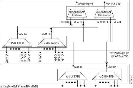
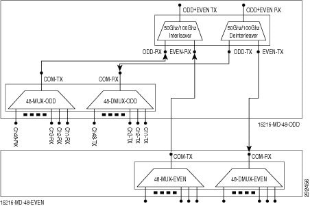
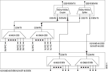
The optical interconnections between the odd patch panel, ONS 15216-MD-48-CM interleaver and deinterleaver pluggable and the even patch panel is shown in the following figure:The port connections between the odd patch panel (15216-MD-40, 15216-EF-40, or 15216-MD-48), ONS 15216-MD-48-CM interleaver and deinterleaver pluggable, and the even patch panel (15216-MD-40, 15216-EF-40, or 15216-MD-48) are established as follows:
COM-TX port of the odd patch panel and ODD-RX port of the interleaver and deinterleaver pluggable.
COM-RX port of the odd patch panel and ODD-TX port of the interleaver and deinterleaver pluggable.
COM-TX port of the even patch panel and EVEN-RX port of the interleaver and deinterleaver pluggable.
COM-RX port of the even patch panel and EVEN-TX port of the interleaver and deinterleaver pluggable.
Optical Interconnections for ONS 15216-MD-48-CME
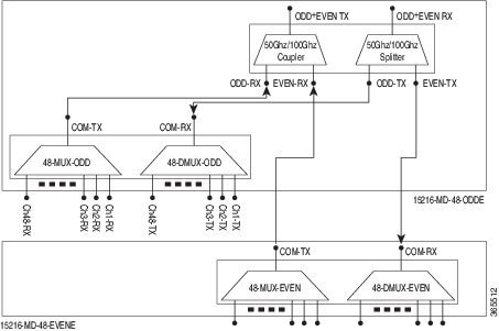
The optical interconnections between the odd patch panel, ONS 15216-MD-48-CME coupler and splitter pluggable and the even patch panel is shown in the following figure:The port connections between the odd patch panel (15216-MD-40, 15216-EF-40, or 15216-MD-48), ONS 15216-MD-48-CME coupler and splitter pluggable, and the even patch panel (15216-MD-40, 15216-EF-40, or 15216-MD-48) are established as follows:
Channel Wavelength Allocation
The following table describes the C-band channel wavelength allocation plan for the odd and even patch panels.
Table 1 15216-MD-40 and 15216-EF-40 Odd and Even Patch Panels C-Band Channel Wavelength Allocation Plan Channel Wavelength Channel Wavelength 15216-MD-40-ODD/15216-EF-40-ODD 15216-MD-40-ODD/15216-EF-40-EVEN Channel Label Frequency (THz) Wavelength (nm) Channel Label Frequency (THz) Wavelength (nm) 1 195.9 1530.33 1 195.85 1530.72 2 195.8 1531.12 2 195.75 1531.51 3 195.7 1531.90 3 195.65 1532.29 4 195.6 1532.68 4 195.55 1533.07 5 195.5 1533.47 5 195.45 1533.86 6 195.4 1534.25 6 195.35 1534.64 7 195.3 1535.04 7 195.25 1535.43 8 195.2 1535.82 8 195.15 1536.22 9 195.1 1536.61 9 195.05 1537.00 10 195 1537.40 10 194.95 1537.79 11 194.9 1538.19 11 194.85 1538.58 12 194.8 1538.98 12 194.75 1539.37 13 194.7 1539.77 13 194.65 1540.16 14 194.6 1540.56 14 194.55 1540.95 15 194.5 1541.35 15 194.45 1541.75 16 194.4 1542.14 16 194.35 1542.54 17 194.3 1542.94 17 194.25 1543.33 18 194.2 1543.73 18 194.15 1544.13 19 194.1 1544.53 19 194.05 1544.92 20 194 1545.32 20 193.95 1545.72 21 193.9 1546.12 21 193.85 1546.52 22 193.8 1546.92 22 193.75 1547.32 23 193.7 1547.72 23 193.65 1548.11 24 193.6 1548.51 24 193.55 1548.91 25 193.5 1549.32 25 193.45 1549.72 26 193.4 1550.12 26 193.35 1550.52 27 193.3 1550.92 27 193.25 1551.32 28 193.2 1551.72 28 193.15 1552.12 29 193.1 1552.52 29 193.05 1552.93 30 193 1553.33 30 192.95 1553.73 31 192.9 1554.13 31 192.85 1554.54 32 192.8 1554.94 32 192.75 1555.34 33 192.7 1555.75 33 192.65 1556.15 34 192.6 1556.55 34 192.55 1556.96 35 192.5 1557.36 35 192.45 1557.77 36 192.4 1558.17 36 192.35 1558.58 37 192.3 1558.98 37 192.25 1559.39 38 192.2 1559.79 38 192.15 1560.20 39 192.1 1560.61 39 192.05 1561.01 40 192 1561.42 40 191.95 1561.83
Table 2 15216-MD-48 Odd and Even Patch Panels C-Band Channel Wavelength Allocation Plan Channel Wavelength Channel Wavelength 15216-MD-48-ODD/15216-MD-48-ODDE 15216-MD-48-EVEN/15216-MD-48-EVENE Channel Label Frequency (THz) Wavelength (nm) Channel Label Frequency (THz) Wavelength (nm) 1 196.1 1528.77 1 196.05 1529.16 2 196.0 1529.55 2 195.95 1529.94 3 195.9 1530.33 3 195.85 1530.72 4 195.8 1531.12 4 195.75 1531.51 5 195.7 1531.90 5 195.65 1532.29 6 195.6 1532.68 6 195.55 1533.07 7 195.5 1533.47 7 195.45 1533.86 8 195.4 1534.25 8 195.35 1534.64 9 195.3 1535.04 9 195.25 1535.43 10 195.2 1535.82 10 195.15 1536.22 11 195.1 1536.61 11 195.05 1537.00 12 195 1537.40 12 194.95 1537.79 13 194.9 1538.19 13 194.85 1538.58 14 194.8 1538.98 14 194.75 1539.37 15 194.7 1539.77 15 194.65 1540.16 16 194.6 1540.56 16 194.55 1540.95 17 194.5 1541.35 17 194.45 1541.75 18 194.4 1542.14 18 194.35 1542.54 19 194.3 1542.94 19 194.25 1543.33 20 194.2 1543.73 20 194.15 1544.13 21 194.1 1544.53 21 194.05 1544.92 22 194 1545.32 22 193.95 1545.72 23 193.9 1546.12 23 193.85 1546.52 24 193.8 1546.92 24 193.75 1547.32 25 193.7 1547.72 25 193.65 1548.11 26 193.6 1548.51 26 193.55 1548.91 27 193.5 1549.32 27 193.45 1549.72 28 193.4 1550.12 28 193.35 1550.52 29 193.3 1550.92 29 193.25 1551.32 30 193.2 1551.72 30 193.15 1552.12 31 193.1 1552.52 31 193.05 1552.93 32 193 1553.33 32 192.95 1553.73 33 192.9 1554.13 33 192.85 1554.54 34 192.8 1554.94 34 192.75 1555.34 35 192.7 1555.75 35 192.65 1556.15 36 192.6 1556.55 36 192.55 1556.96 37 192.5 1557.36 37 192.45 1557.77 38 192.4 1558.17 38 192.35 1558.58 39 192.3 1558.98 39 192.25 1559.39 40 192.2 1559.79 40 192.15 1560.20 41 192.1 1560.61 41 192.05 1561.01 42 192 1561.42 42 191.95 1561.83 43 191.9 1562.23 43 191.85 1562.64 44 191.8 1563.05 44 191.75 1563.45 45 191.7 1563.86 45 191.65 1564.27 46 191.6 1564.68 46 191.55 1565.09 47 191.5 1565.50 47 191.45 1565.90 48 191.4 1566.31 48 191.35 1566.72 Port Label Description
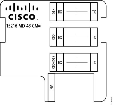
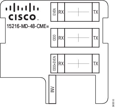
The following table lists the connection ports, description, and the type of connectors used for each port. All ports are on the front faceplate of ONS 15216-MD-48-CM/15216-MD-48-CME, which is equipped with optical LC adapters and one USB Type A receptacle connector.
Table 3 Port Label Descriptions Port Label Description Type of Connector ODD+EVEN-RX Common input LC-UPC II ODD-TX Odd channels output LC-UPC II EVEN-TX Even channels output LC-UPC II ODD+EVEN-TX Common output LC-UPC II ODD-RX Odd channels input LC-UPC II EVEN-RX Even channels input LC-UPC II INV USB inventory port USB Type A receptacle connector Channel Identification Label
Safety Information
Before you install, operate, or service this product, you must read the Regulatory Compliance and Safety Information for Cisco Optical Transport Products document for important safety information and warning translations.
This product is compliant with the GR 1089, UL60950 /CSA 22.2 No. 60950-00, and IEC 60950 standards.
Laser Radiation Emission Restrictions
The Class 1M Laser safety and warning label is affixed to this product and indicates that the product should never be used or installed in an optical network with emissions higher than Class 1M.
Warning
Class 1M laser radiation when open. Do not view directly with optical instruments. Statement 281
Warning
Invisible laser radiation may be emitted from disconnected fibers or connectors. Do not stare into beams or view directly with optical instruments. Statement 1051Unpacking and Verifying the ONS 15216-MD-48-CM/15216-MD-48-CME Pluggable
Procedure
Installing the ONS 15216-MD-48-CM/15216-MD-48-CME Pluggable
ProcedureThe following procedure explains how to install the ONS 15216-MD-48-CM/15216-MD-48-CME pluggable inside the 15216-EF-40 or 15216-MD-48 odd and even patch panels. To install the ONS 15216-MD-48-CM/15216-MD-48-CME inside the 15216-MD-40 odd or even patch panel, see the "Installing Cisco ONS 15216-MD-ID-50 Optical Interleaver and Deinterleaver Pluggable"guide.
Caution
Use only the fastening hardware provided with the ONS 15216-MD-48-CM/15216-MD-48-CME to prevent loosening, deterioration, and electromechanical corrosion of the hardware and joined material.
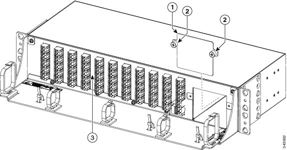
Step 1 Unscrew the captive screws to remove the Interleaver/Deinterleaver (I/D) or the Coupler/Splitter blank cover from the patch panel as shown in the following figure:
Note During an in-field upgrade, all the fibers installed previously must be routed toward the left fiber bend radius controller. To plug in the pluggable, the space in front of the I/D blank cover must be free of fibers and cables.
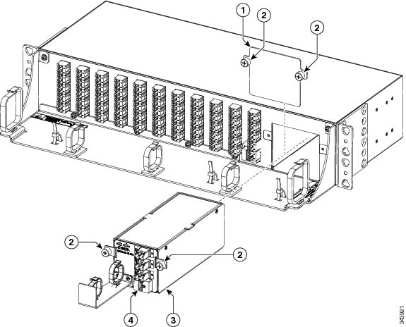
Step 2 Insert the ONS 15216-MD-48-CM/15216-MD-48-CME pluggable as shown in the following figure: Step 3 Tighten the screws of the ONS 15216-MD-48-CM/15216-MD-48-CME pluggable. For installing and routing fiber-optic and USB cables, see "Install and Route Fiber-Optic and USB Cables". For cleaning the fiber-optic connectors, see "Cleaning and Maintaining Fiber-Optic Connectors".
Install and Route Fiber-Optic and USB Cables
ProcedureAll connectors are on the front of the ONS 15216-MD-48-CM/15216-MD-48-CME pluggable and are equipped with LC/UPC bulkhead adapters and with a USB Type A receptacle connector for inventory purpose. For port label description, see "Table 1". The LC-LC patch cords are used to connect the ONS 15216-MD-48-CM/15216-MD-48-CME pluggable to the patch panels.
Warning
Invisible laser radiation may be emitted from disconnected fibers or connectors. Do not stare into beams or view directly with optical instruments. Statement 1051
Caution
When connecting an optical fiber patch cord between the patch panel and the optical card ports in a Cisco ONS 15454, use the electrostatic discharge wristband supplied with the ONS 15454. Plug the wristband into the ESD jack on the lower right front side of the ONS 15454.
Note
Always clean all fiber connectors thoroughly before making the connection with the mating adapter. Very small particles can permanently damage the end of the mating fiber inside the patch panel, which makes regular cleaning imperative. For cleaning instructions see "Cleaning Fiber-Optic Cable Connectors".
Caution
The ONS 15216-MD-48-CM/15216-MD-48-CME pluggables have LC/UPC bulkhead adapters for optical connections. Always use fiber-optic cables equipped with the corresponding (LC/UPC) connector type. Using any other type of connector results in damage to the connector or adapter, or both.
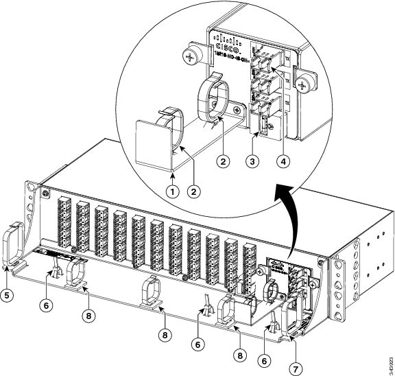
Step 1 To connect the fibers as appropriate (see the following figure):
For interconnections between the ONS 15216-MD-48-CM/15216-MD-48-CME pluggables, odd or even patch panel with a patch panel of a different grid, see "Optical Interconnections".
Step 2 To secure the fibers, bundle the fibers using one of the four velcro strips that is provided. Step 3 To connect and secure the inventory USB Type A plug connector to the inventory USB Type A receptacle connector (see Figure 1):
Uninstalling the ONS 15216-MD-48-CM/15216-MD-48-CME Pluggable
Procedure
Cleaning and Maintaining Fiber-Optic Connectors
Connector cleaning is required to maintain the performance of fiber-optic circuits. It is important that both the LC/UPC connector at the end of the fiber-optic cable and the optical mating adapter on the front panel of the device are clean before the connection is made.
Warning
Invisible laser radiation may be emitted from disconnected fibers or connectors. Do not stare into beams or view directly with optical instruments. Statement 1051
The following warning applies to disposal of chemicals and other materials used to clean connectors and adapters:
Warning
Ultimate disposal of this product should be handled according to all national laws and regulations. Statement 1040
Note
Before installing the fiber-optic cable, always perform the cleaning procedure for cable connectors described in the following section. Whenever possible, inspect each connector before connecting it to the optical mating adapter on the front panel.
Note
The LC optical mating adapter on the faceplate of the device is less likely to get dirty if it is capped when not in use. On some devices, the optical mating adapter has a shutter. The shutter automatically closes when the LC/UPC connector is disconnected. This prevents entry of dirt.
The procedure for a thorough cleaning of these adapters is complicated. Use a commercially available cleaning kit and closely follow the instructions included with the kit.
Customer-supplied Cleaning Materials
The Type A fiber optic connector cleaners (for example, CLETOP reel) are recommended to clean the cable connectors, but are not supplied with the device.
If properly maintained (only used with clean, defect-free fiber connectors and capped when not in use), the mating adapter would not require cleaning. However, if you suspect the adapter is dirty, clean it by using the CLETOP stick swab.
Note
For multifiber cable assemblies, use specific cleaning tools or materials designed for the assembly type.
Cleaning the Optical Mating Adapter
Procedure
Cleaning Fiber-Optic Cable Connectors
Procedure
Step 1 Using an inspection microscope, inspect each fiber connector for dirt, cracks, or scratches. Step 2 Replace any damaged fiber connectors.
Note Replace all dust caps whenever the equipment is unused for 30 minutes or more.
Caution Do not reuse optical swabs. Keep unused swabs off of work surfaces.
Step 3 Clean the fiber connectors with CLETOP reel:
- If present, remove the dust cap from the fiber connector.
- Press the lever down to open the shutter door. Each time you press the lever, you expose a clean wiping surface.
- Insert the connector into the CLETOP cleaning cassette slot, rotate one-quarter turn, and gently swipe downwards.
- Use an inspection microscope to inspect each fiber connector for dirt, cracks, or scratches. If the connector is not clean, repeat the above sub-steps.
- Insert the fiber connector into the applicable adapter or attach a dust cap to the fiber connector.
Note Before replacing a dust cap on a connector, verify that the dust cap is clean. To clean the dust cap, wipe the outside of the cap using a dry, lint-free wipe and the inside of the dust cap using a CLETOP stick swab (14100400).
Cisco ONS 15216-MD-48-CM/15216-MD-48-CME Pluggable Specifications
This section contains environmental, power, optical, connector and mechanical specifications for the ONS 15216-MD-48-CM/15216-MD-48-CME pluggable.
Environmental and Power Specifications
Table 4 Environmental and Power Specifications for ONS 15216-MD-48-CM Environmental Condition Minimum Maximum Units Short Term (96 hours/year) Temperature Range (STR) -5 65 Celsius 23 149 Fahrenheit Continuous Operative Temperature Range (OTR) 5 40 Celsius 41 104 Fahrenheit Power handling for the optical port 500 — mW Power handling for the USB Port 400 600 mW Optical Specifications
Table 6 Optical Specifications for ONS 15216-MD-48-CM Parameter Condition Min Typical Max Units 50 GHz /100 GHz Channel Grids ITU Channel Center Frequencies /Wavelength 191.35 — 196.10 THz ITU Channel Spacing 1528.77 — 1566.72 nm 50 — GHz Number of Channels 96 — ITU Channel center frequencies/Wavelength (ODD Grid)
191.40 — 196.10 THz 1528.77 — 1566.31 nm ITU Channel spacing - ODD Grid 100 — GHz Number of Channels 48 — ITU Channel center frequencies/Wavelength (EVEN Grid)
191.35 — 196.05 THz 1529.16 — 1566.72 nm ITU Channel spacing - EVEN Grid 100 — GHz Number of Channels 48 — Deinterleaver Module Operating Bandwidth ± 10
— — GHz Bandwidth at -0.5 dB ± 10
± 11
— GHz Bandwidth at -1.0 dB ± 12
± 13
— GHz Bandwidth at -3.0 dB ± 16
± 17
— GHz Bandwidth at -0.5 dB ± 8
± 9
— GHz Bandwidth at -1.0 dB ± 10
± 12
— GHz Bandwidth at -3.0 dB ± 14
± 16
— GHz DMX Adjacent Channel Isolation1 25
28
— dB Insertion Loss EOL— COM-RX to ODD-TX path and COM-RX to EVEN-TX path
0.5
± 1.8
2.5
dB Insertion Loss Uniformity2 — 0.35 0.5
dB Channels Band Ripple — — 0.5 dB Group Delay Ripple (GDR)3 — 1.8 ± 2.5
ps Chromatic Dispersion4 — ± 15
± 45
ps/nm Optical Return Loss 40.0
45.0
— dB Polarization Dispersion Loss (PDL)5 — 0.3
0.4
dB Polarization Mode Dispersion (PMD)6 — 0. 25
0.3
ps Directivity ODD-TX<– –> EVEN-TX ports
40.0
— — dB Interleaver Module (50%/50% Coupler) Wavelength range 1525 to 1570
— — nm Insertion Loss EOL— COM-RX to ODD-TX path and COM-RX to EVEN-TX path
2.5 — 3.6 dB Insertion Loss Uniformity7 — — 0.5 Insertion Loss Ripple8 — — 0.2 dB Chromatic Dispersion — — ± 5
ps/nm Optical Return Loss 40.0 — — dB Polarization Dispersion Loss — — 0.1 dB Polarization Mode Dispersion — — 0.1 Directivity ODD-RX<– –> EVEN-RX ports
50.0 — — dB 1 Adjacent Channel Isolation is defined as the difference between the maximum IL in the 50 GHz transmitted channel Bandwidth (ITU ± 80 pm) and the minimum IL measured over the Operating Wavelength Bandwidth (± 80 pm, centered on each ITU wavelength of the channel) of both adjacent 100 GHz channels.2 Defined as the difference between the maximum insertion losses over any two wavelengths in the wavelength range.3 The difference between the maximum and minimum group delay in the Operating Wavelength Bandwidth of each channel evaluated at all SOP.4 Chromatic Dispersion is defined as the maximum of derivative of the Group Delay versus the wavelength curve in the 50 GHz transmitted channel bandwidth (Operating Wavelength Bandwidth)5 PDL (Polarization Dependent Loss) is defined as the difference between the maximum and minimum IL in the 100 GHz transmitted channel Bandwidth (Operating Wavelength Bandwidth) evaluated at all SOP, measured at a given wavelength.6 PMD (Polarization Mode Dispersion) is defined as the maximum of the DGD versus the wavelength curve in the 50 GHz transmitted channel bandwidth (Operating Wavelength Bandwidth).7 Defined as the difference between the insertion loss values of the ODD-RX —>COM-TX and the EVEN-RX —>COM-TX paths.8 Difference between the maximum and minimum Insertion Loss values measured within the overall Operating Wavelength Bandwidth.
Table 7 Optical Specifications for ONS 15216-MD-48-CME Parameter Condition Min Typical Max Units 50 GHz /100 GHz Channel Grids ITU Channel Center Frequencies /Wavelength 191.35 — 196.1 THz 1566.72 — 1528.77 nm Insertion Loss EOL— ODD-RX to COM-TX path EVEN-RX to COM-TX path
2.5
—
3.5
dB Insertion Loss Uniformity9 — — 0.6
dB Insertion Loss Ripple10 — — 0.25
dB Chromatic Dispersion11 — — ± 5
ps/nm Optical Return Loss 40.0
— — dB Polarization Dispersion Loss (PDL)12 — — 0.15
dB Polarization Mode Dispersion (PMD)13 — — 0.1
ps Directivity ODD-RX<– –> EVEN-RX ports
50
— — dB 9 Defined as the difference between the maximum insertion losses over any two wavelengths in the wavelength range.10 Difference between the maximum and minimum Insertion Loss values measured within the overall Operating Wavelength Bandwidth.11 Chromatic Dispersion is defined as the maximum of derivative of the Group Delay versus the wavelength curve in the 50 GHz transmitted channel bandwidth (Operating Wavelength Bandwidth)12 PDL (Polarization Dependent Loss) is defined as the difference between the maximum and minimum IL in the 100 GHz transmitted channel Bandwidth (Operating Wavelength Bandwidth) evaluated at all SOP, measured at a given wavelength.13 PMD (Polarization Mode Dispersion) is defined as the maximum of the DGD versus the wavelength curve in the 50 GHz transmitted channel bandwidth (Operating Wavelength Bandwidth).Connector and Mechanical Specifications
Table 8 Connector and Mechanical Specifications Parameter Condition Specification Connector Type All optical ports LC/UPC II USB inventory port USB Type A receptacle connector Adapter Type All optical ports LC Patch Panel Dimensions 9.911-inches (251.7 mm) long, 2.645-inches (67.2 mm) wide, and 2.452-inches (62.2 mm) high. Considering the captive screw brackets, the interleaver and deinterleaver module width is 3.54-inches (89.9 mm). Cisco and the Cisco logo are trademarks or registered trademarks of Cisco and/or its affiliates in the U.S. and other countries. To view a list of Cisco trademarks, go to this URL: http://www.cisco.com/go/trademarks. Third-party trademarks mentioned are the property of their respective owners. The use of the word partner does not imply a partnership relationship between Cisco and any other company. (1110R)
Obtaining Documentation and Submitting a Service Request
For information on obtaining documentation, submitting a service request, and gathering additional information, see the monthly What's New in Cisco Product Documentation, which also lists all new and revised Cisco technical documentation, at: http://www.cisco.com/en/US/docs/general/whatsnew/whatsnew.html
Subscribe to the What's New in Cisco Product Documentation as a Really Simple Syndication (RSS) feed and set content to be delivered directly to your desktop using a reader application. The RSS feeds are a free service and Cisco currently supports RSS version 2.0.
Cisco and the Cisco logo are trademarks or registered trademarks of Cisco and/or its affiliates in the U.S. and other countries. To view a list of Cisco trademarks, go to this URL: http://www.cisco.com/go/trademarks. Third-party trademarks mentioned are the property of their respective owners. The use of the word partner does not imply a partnership relationship between Cisco and any other company. (1110R)
Copyright © , Cisco Systems, Inc. All rights reserved.


 Feedback
Contact Cisco
- Open a Support Case

- (Requires a Cisco Service Contract)