- About This Guide
- Chapter 1, Install the Shelf and Common Control Cards
- Chapter 2, Connect the PC and Log into the GUI
- Chapter 3, Turn Up a Node
- Chapter 4, Perform Node Acceptance Tests
- Chapter 5, Provision Transponder and Muxponder Cards
- Chapter 6, Turn Up a Network
- Chapter 7, Create Optical Channel Circuits and Provisionable Patchcords
- Chapter 8, Monitor Performance
- Chapter 9, Manage Alarms
- Chapter 10, Manage the Node
- Chapter 11, Change DWDM Card Settings
- Chapter 12, Upgrade, Add, and Remove Cards and Nodes
- Chapter 13, Maintain the Node
- Chapter 14, Power Down a Node
- Appendix A, CTC Information and Shortcuts
- Appendix B, Installation Without Cisco Transport Planner
- Appendix C, Configuring GE_XP, 10GE_XP, GE_XPE, and 10GE_XPE Cards Using PCLI
Turn Up a Node
This chapter explains how to provision a single Cisco ONS 15454 dense wavelength division multiplexing (DWDM) node and turn it up for service, including assigning the node name, date, and time; provisioning timing references; provisioning network attributes such as IP address and default router; setting up users and user security; installing cards; and creating DWDM connections.

Note![]() Procedures in this chapter require that you have a network plan calculated for your DWDM network with Cisco TransportPlanner, Release 9.0. Cisco TransportPlanner is a DWDM planning tool that is available from your Cisco account representative. Cisco TransportPlanner prepares a shelf plan for each network node and calculates the power and attenuation levels for the DWDM cards installed in the node. For information about Cisco TransportPlanner, contact your Cisco account representative. For instructions on using Cisco TransportPlanner, refer to the Cisco TransportPlanner DWDM Operations Guide, Release 9.0.
Procedures in this chapter require that you have a network plan calculated for your DWDM network with Cisco TransportPlanner, Release 9.0. Cisco TransportPlanner is a DWDM planning tool that is available from your Cisco account representative. Cisco TransportPlanner prepares a shelf plan for each network node and calculates the power and attenuation levels for the DWDM cards installed in the node. For information about Cisco TransportPlanner, contact your Cisco account representative. For instructions on using Cisco TransportPlanner, refer to the Cisco TransportPlanner DWDM Operations Guide, Release 9.0.
Note![]() Unless otherwise specified, in this document “ONS 15454” refers to both ANSI (ONS 15454) and ETSI (ONS 15454 SDH) shelf assemblies.
Unless otherwise specified, in this document “ONS 15454” refers to both ANSI (ONS 15454) and ETSI (ONS 15454 SDH) shelf assemblies.
Note![]() Cisco Transport Controller (CTC) views referenced in these procedures depend on the ONS 15454 mode. In single-shelf mode, the views are network, node, and card. In multishelf mode, the views are network, multishelf, shelf, and card. For more information about CTC views, refer to Appendix A, “CTC Information and Shortcuts.”
Cisco Transport Controller (CTC) views referenced in these procedures depend on the ONS 15454 mode. In single-shelf mode, the views are network, node, and card. In multishelf mode, the views are network, multishelf, shelf, and card. For more information about CTC views, refer to Appendix A, “CTC Information and Shortcuts.”
Before You Begin
This section lists the non-trouble procedures (NTPs) needed to turn up a DWDM node. Turn to an NTP for applicable detail-level procedures (DLPs), known as tasks.
1.![]() G139 Verify Cisco TransportPlanner Reports and Files—Complete this procedure first.
G139 Verify Cisco TransportPlanner Reports and Files—Complete this procedure first.
2.![]() G22 Verify Common Card Installation—Complete this procedure next.
G22 Verify Common Card Installation—Complete this procedure next.
3.![]() G144 Provision a Multishelf Node—Complete this procedure as needed.
G144 Provision a Multishelf Node—Complete this procedure as needed.
4.![]() G23 Create Users and Assign Security —Complete this procedure to create CTC users and assign their security levels.
G23 Create Users and Assign Security —Complete this procedure to create CTC users and assign their security levels.
5.![]() G24 Set Up Name, Date, Time, and Contact Information—Continue with this procedure to set the node name, date, time, location, and contact information.
G24 Set Up Name, Date, Time, and Contact Information—Continue with this procedure to set the node name, date, time, location, and contact information.
6.![]() G25 Set Battery Power Monitor Thresholds—Continue with this procedure to set the node battery power thresholds.
G25 Set Battery Power Monitor Thresholds—Continue with this procedure to set the node battery power thresholds.
7.![]() G26 Set Up CTC Network Access—Continue with this procedure to provision the IP address, default router, subnet mask, and other network configuration settings.
G26 Set Up CTC Network Access—Continue with this procedure to provision the IP address, default router, subnet mask, and other network configuration settings.
8.![]() G194 Set Up EMS Secure Access to the ONS 15454—Continue with this procedure to connect the CTC in secure mode.
G194 Set Up EMS Secure Access to the ONS 15454—Continue with this procedure to connect the CTC in secure mode.
9.![]() G341 Set Up Secure Access to the ONS 15454 TL1—Continue with this procedure to enable secure access to TL1.
G341 Set Up Secure Access to the ONS 15454 TL1—Continue with this procedure to enable secure access to TL1.
10.![]() G27 Set Up the ONS 15454 for Firewall Access—Continue with this procedure if the ONS 15454 will be accessed behind firewalls.
G27 Set Up the ONS 15454 for Firewall Access—Continue with this procedure if the ONS 15454 will be accessed behind firewalls.
11.![]() G28 Create FTP Host - Continue with this procedure if to create FTP host for ENE database backup.
G28 Create FTP Host - Continue with this procedure if to create FTP host for ENE database backup.
12.![]() G132 Provision OSI—Continue with this procedure if the ONS 15454 will be installed in networks with third-party, Open Systems Interconnection (OSI)-based network elements (NEs).
G132 Provision OSI—Continue with this procedure if the ONS 15454 will be installed in networks with third-party, Open Systems Interconnection (OSI)-based network elements (NEs).
13.![]() G29 Set Up SNMP —Complete this procedure if Simple Network Management Protocol (SNMP) will be used for network monitoring.
G29 Set Up SNMP —Complete this procedure if Simple Network Management Protocol (SNMP) will be used for network monitoring.
14.![]() G143 Import the Cisco TransportPlanner NE Update Configuration File—Complete this procedure to preprovision the ONS 15454 slots and install the card and automatic node setup (ANS) parameters.
G143 Import the Cisco TransportPlanner NE Update Configuration File—Complete this procedure to preprovision the ONS 15454 slots and install the card and automatic node setup (ANS) parameters.
15.![]() G30 Install the DWDM Cards —Complete this procedure to install the DWDM cards, including the OSCM, OSC-CSM, 32WSS, 32WSS-L, 40-WSS-C, 40-WSS-CE, 40-WXC-C, OPT-BST, OPT-BST-E, OPT-BST-L, OPT-AMP-L, OPT-AMP-17-C, OPT-AMP-C, OPT-RAMP-C, OPT-PRE, 32MUX-O, 40-MUX-C, 32DMX-O, 32DMX, 32DMX-L, 40-DMX-C, 40-DMX-CE, 4MD-xx.x, AD-1C-xx.x, AD-2C-xx.x, AD-4C-xx.x, AD-1B-xx.x, AD-4B-xx.x, MMU, and PSM.
G30 Install the DWDM Cards —Complete this procedure to install the DWDM cards, including the OSCM, OSC-CSM, 32WSS, 32WSS-L, 40-WSS-C, 40-WSS-CE, 40-WXC-C, OPT-BST, OPT-BST-E, OPT-BST-L, OPT-AMP-L, OPT-AMP-17-C, OPT-AMP-C, OPT-RAMP-C, OPT-PRE, 32MUX-O, 40-MUX-C, 32DMX-O, 32DMX, 32DMX-L, 40-DMX-C, 40-DMX-CE, 4MD-xx.x, AD-1C-xx.x, AD-2C-xx.x, AD-4C-xx.x, AD-1B-xx.x, AD-4B-xx.x, MMU, and PSM.
16.![]() G31 Install the DWDM Dispersion Compensating Units—Complete this procedure, as needed, to install a dispersion compensating unit (DCU).
G31 Install the DWDM Dispersion Compensating Units—Complete this procedure, as needed, to install a dispersion compensating unit (DCU).
17.![]() G179 Install the TXP, MXP, GE_XP, 10GE_XP, GE_XPE, 10GE_XPE, ADM-10G, and OTU2_XP Cards—Complete this procedure, as needed, to install transponder (TXP), muxponder (MXP), GE_XP, 10GE_XP, GE_XPE, or 10GE_XPE, ADM-10G, or OTU2_XP cards.
G179 Install the TXP, MXP, GE_XP, 10GE_XP, GE_XPE, 10GE_XPE, ADM-10G, and OTU2_XP Cards—Complete this procedure, as needed, to install transponder (TXP), muxponder (MXP), GE_XP, 10GE_XP, GE_XPE, or 10GE_XPE, ADM-10G, or OTU2_XP cards.
18.![]() G123 Install the Filler Cards—Complete this procedure, as needed, to install ONS 15454 filler cards.
G123 Install the Filler Cards—Complete this procedure, as needed, to install ONS 15454 filler cards.
19.![]() G34 Install Fiber-Optic Cables on DWDM Cards and DCUs —Complete this procedure, as needed, to install the fiber-optic cables on the DWDM cards.
G34 Install Fiber-Optic Cables on DWDM Cards and DCUs —Complete this procedure, as needed, to install the fiber-optic cables on the DWDM cards.
20.![]() G140 Install Fiber-Optic Cables Between Terminal, Hub, or ROADM Nodes —Complete this procedure, as needed, to connect TXP, MXP, GE_XP, 10GE_XP, GE_XPE, or 10GE_XPE, ADM-10G, or OTU2_XP cards to DWDM cards in a terminal, hub, or reconfigurable optical add-drop multiplexer (ROADM) node through the patch panel.
G140 Install Fiber-Optic Cables Between Terminal, Hub, or ROADM Nodes —Complete this procedure, as needed, to connect TXP, MXP, GE_XP, 10GE_XP, GE_XPE, or 10GE_XPE, ADM-10G, or OTU2_XP cards to DWDM cards in a terminal, hub, or reconfigurable optical add-drop multiplexer (ROADM) node through the patch panel.
21.![]() G185 Install Fiber-Optic Cables between Mesh Nodes —Complete this procedure, as needed, to connect 40-WXC-C cards in a mesh node to the 4-degree or 8-degree patch panel.
G185 Install Fiber-Optic Cables between Mesh Nodes —Complete this procedure, as needed, to connect 40-WXC-C cards in a mesh node to the 4-degree or 8-degree patch panel.
22.![]() G141 Install Fiber-Optic Cables for Y-Cable Protection Modules —Complete this procedure, as needed, to connect fiber-optic cables to Y-cable modules from client TXP, MXP, GE_XP, 10GE_XP, GE_XPE, or 10GE_XPE cards.
G141 Install Fiber-Optic Cables for Y-Cable Protection Modules —Complete this procedure, as needed, to connect fiber-optic cables to Y-cable modules from client TXP, MXP, GE_XP, 10GE_XP, GE_XPE, or 10GE_XPE cards.
23.![]() G152 Create and Verify Internal Patchcords—Complete this procedure to calculate the DWDM cable connections.
G152 Create and Verify Internal Patchcords—Complete this procedure to calculate the DWDM cable connections.
24.![]() G209 Create, Edit, and Delete Optical Sides—Complete this procedure to create, edit, and delete an optical side.
G209 Create, Edit, and Delete Optical Sides—Complete this procedure to create, edit, and delete an optical side.
25.![]() G38 Provision OSC Terminations—Complete this procedure next.
G38 Provision OSC Terminations—Complete this procedure next.
26.![]() G37 Run Automatic Node Setup—Complete this procedure next.
G37 Run Automatic Node Setup—Complete this procedure next.
27.![]() G39 Verify OSCM Transmit Power—Complete this procedure next.
G39 Verify OSCM Transmit Power—Complete this procedure next.
28.![]() G163 Upgrade Nodes in Single-Shelf Mode to Multishelf Mode—Complete this procedure as needed.
G163 Upgrade Nodes in Single-Shelf Mode to Multishelf Mode—Complete this procedure as needed.
29.![]() G210 Provision Node for SNMPv3 —Complete this procedure if Simple Network Management Protocol version 3(SNMPv3) will be used for network monitoring.
G210 Provision Node for SNMPv3 —Complete this procedure if Simple Network Management Protocol version 3(SNMPv3) will be used for network monitoring.
NTP-G139 Verify Cisco TransportPlanner Reports and Files
This procedure verifies that you have the Cisco TransportPlanner reports and files needed to turn up the node. |
|
Step 1![]() Verify that you have the Cisco TransportPlanner reports and files shown in Table 3-1 for the node that you will provision. The reports and files can be provided in one of the following ways:
Verify that you have the Cisco TransportPlanner reports and files shown in Table 3-1 for the node that you will provision. The reports and files can be provided in one of the following ways:
- If you have Cisco TransportPlanner, verify that you have the electronic network design plan from which you can generate the reports in Cisco TransportPlanner. For information about generating the reports, refer to the Cisco TransportPlanner DWDM Operations Guide.
- If you do not have Cisco TransportPlanner, you must have printouts of all reports listed in Table 3-1 except the Assisted Configuration Setup file. Assisted Configuration Setup is an electronic file that will be imported into CTC. You must be able to access it from the CTC computer used to provision the node.
|
|
|
|
|---|---|---|
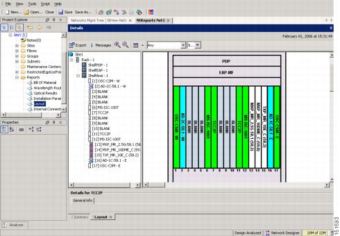
Cisco TransportPlanner provides a shelf layout (Figure 3-1) showing the cards that should be installed in each ONS 15454 slot. Cisco TransportPlanner can export this as a JPG file with a user-defined name. |
||
Provides the target reference values for the variable optical attenuators (VOAs), output power, optical thresholds, and amplifier configuration parameters. |
||
Identifies the patchcords that must be installed within the shelf. |
||
The Cisco TransportPlanner NE Update configuration file is an electronic file with an XML extension and a name assigned by the network designer for the network you are provisioning. The file is imported into CTC where it preprovisions the shelf and configures the following card parameters: OTN and FEC parameters for TXP, MXP, GE_XP, 10GE_XP, GE_XPE, 10GE_XPE, ADM-10G, and OTU2_XP cards; card mode for OPT-AMP-L, OPT-AMP-17-C, OPT-AMP-C, GE_XP, 10GE_XP, GE_XPE, and 10GE_XPE cards; and optical switching threshold for PSM card. It also provisions the OCH trunk to OCH filter internal patchcords, the optical sides. and it configures the ANS parameters based on the network calculated by Cisco TransportPlanner. |
||
Shows the traffic flow within the node. During node turn-up, this report is used to identify the location of Y-cable protection groups. |
||
A list of cables needed to provision the node. The list can be derived from the Internal Connections Report or from the Bill of Materials report prepared by Cisco TransportPlanner. |
Figure 3-1 Cisco TransportPlanner Shelf Layout
If you not do not have all the reports and files listed in Table 3-1 , do not continue. See your site or network planner for the required information and files.
Step 2![]() Print Table 3-1 for reference. You will need information from the reports during node turn-up.
Print Table 3-1 for reference. You will need information from the reports during node turn-up.
Stop. You have completed this procedure.
NTP-G22 Verify Common Card Installation
This procedure verifies that the ONS 15454 node has two TCC2 or TCC2P cards installed. It also verifies the installation of the AIC-I and MS-ISC-100T cards, if they are installed. |
|
Step 1![]() Verify that two TCC2 cards or two TCC2P cards are installed in Slots 7 and 11.
Verify that two TCC2 cards or two TCC2P cards are installed in Slots 7 and 11.
Step 2![]() Verify that the FAIL LED is off on both TCC2/TCC2P cards.
Verify that the FAIL LED is off on both TCC2/TCC2P cards.
Step 3![]() Verify that the green ACT (active) LED is illuminated on one TCC2/TCC2P card and that the amber STBY (standby) LED is illuminated on the other TCC2/TCC2P card.
Verify that the green ACT (active) LED is illuminated on one TCC2/TCC2P card and that the amber STBY (standby) LED is illuminated on the other TCC2/TCC2P card.
Note![]() If the TCC2/TCC2P cards are not installed, or if their LEDs are not operating as described, do not continue. Complete the G33 Install the TCC2 or TCC2P Card or refer to the Cisco ONS 15454 DWDM Troubleshooting Guide to resolve installation problems before proceeding to Step 4.
If the TCC2/TCC2P cards are not installed, or if their LEDs are not operating as described, do not continue. Complete the G33 Install the TCC2 or TCC2P Card or refer to the Cisco ONS 15454 DWDM Troubleshooting Guide to resolve installation problems before proceeding to Step 4.
Step 4![]() If the AIC-I card is installed, verify that it is installed in Slot 9 and that its ACT (active) LED displays a solid green light.
If the AIC-I card is installed, verify that it is installed in Slot 9 and that its ACT (active) LED displays a solid green light.
Note![]() If the AIC-I card is not installed and the card is required by the Cisco TransportPlanner shelf layout, or if it is installed and its LEDs are not operating as described, do not continue. Complete the G34 Install the AIC-I Card or refer to the Cisco ONS 15454 DWDM Troubleshooting Guide to resolve installation problems before proceeding to Step 5.
If the AIC-I card is not installed and the card is required by the Cisco TransportPlanner shelf layout, or if it is installed and its LEDs are not operating as described, do not continue. Complete the G34 Install the AIC-I Card or refer to the Cisco ONS 15454 DWDM Troubleshooting Guide to resolve installation problems before proceeding to Step 5.
Step 5![]() Verify that the software release shown on the LCD matches the software release required for your network. On the LCD, the software release is shown under the platform (SONET or SDH) and date/temperature. If the release does not match, perform one of the following procedures:
Verify that the software release shown on the LCD matches the software release required for your network. On the LCD, the software release is shown under the platform (SONET or SDH) and date/temperature. If the release does not match, perform one of the following procedures:
Step 6![]() If the node will be configured as a multishelf node, verify that redundant MS-ISC-100T cards are installed (Slots 6 and 12 are recommended) and that the green ACT (active) LED is illuminated on both cards.
If the node will be configured as a multishelf node, verify that redundant MS-ISC-100T cards are installed (Slots 6 and 12 are recommended) and that the green ACT (active) LED is illuminated on both cards.
Note![]() If the MS-ISC-100T card is not installed and the card is required by the Cisco TransportPlanner shelf layout, or if the card’s LEDs are not operating as described, do not continue. Complete the G309 Install the MS-ISC-100T Card or refer to the Cisco ONS 15454 DWDM Troubleshooting Guide to resolve installation problems before proceeding to the next procedure.
If the MS-ISC-100T card is not installed and the card is required by the Cisco TransportPlanner shelf layout, or if the card’s LEDs are not operating as described, do not continue. Complete the G309 Install the MS-ISC-100T Card or refer to the Cisco ONS 15454 DWDM Troubleshooting Guide to resolve installation problems before proceeding to the next procedure.
Stop. You have completed this procedure.
NTP-G144 Provision a Multishelf Node
This procedure provisions a multishelf node from CTC. A multishelf node consists of a control node and subtending shelves that are configured to operate as a single node. |
|
G22 Verify Common Card Installation G145 Connect a Multishelf Node and Subtending Shelves to an MS-ISC-100T Card or G158 Connect a Multishelf Node and Subtending Shelves to a Catalyst 2950 |
|

Step 1![]() Complete the G46 Log into CTC at the node that you want to configure as a multishelf node.
Complete the G46 Log into CTC at the node that you want to configure as a multishelf node.
Step 2![]() If you want to set up the login node as the node controller, complete the following steps. If not, continue with Step 3.
If you want to set up the login node as the node controller, complete the following steps. If not, continue with Step 3.
a.![]() In node view (single-node mode) or multishelf view (multishelf mode), click the Provisioning > General > Multishelf Config tabs.
In node view (single-node mode) or multishelf view (multishelf mode), click the Provisioning > General > Multishelf Config tabs.
b.![]() Click Enable as Node Controller.
Click Enable as Node Controller.
c.![]() From the LAN Config drop-down list, complete one of the following:
From the LAN Config drop-down list, complete one of the following:
- Choose Ethernet Switch if MS-ISC-100T cards or the Catalyst 2950 switches are already installed and configured.
- Choose Stand-Alone if MS-ISC-100T cards are not installed yet but will be included in the final layout. This option will allow a safe migration of the TCC2/TCC2P card database when the multishelf configuration is complete.
e.![]() In the confirmation dialog box, click Yes to allow the node to reboot. The CTC view changes to network view and the node icon changes to gray. Wait for the reboot to finish. (This might take several minutes.)
In the confirmation dialog box, click Yes to allow the node to reboot. The CTC view changes to network view and the node icon changes to gray. Wait for the reboot to finish. (This might take several minutes.)
f.![]() After the node reboots, double-click the node. The multishelf view appears.
After the node reboots, double-click the node. The multishelf view appears.
Note![]() The shelf ID of the node controller is automatically assigned as 1.
The shelf ID of the node controller is automatically assigned as 1.
Step 3![]() If you want to add a node as a subtending shelf in the multishelf configuration, complete the following steps. If not, you have completed this procedure.
If you want to add a node as a subtending shelf in the multishelf configuration, complete the following steps. If not, you have completed this procedure.
a.![]() In multishelf view, right-click the white space in the rack and choose Add Shelf from the shortcut menu.
In multishelf view, right-click the white space in the rack and choose Add Shelf from the shortcut menu.
b.![]() In the Shelf ID Selection dialog box, choose a shelf ID (from 2 to 8) from the drop-down list.
In the Shelf ID Selection dialog box, choose a shelf ID (from 2 to 8) from the drop-down list.
c.![]() Click OK. The shelf appears in multishelf view.
Click OK. The shelf appears in multishelf view.
d.![]() Disconnect the cross-over (CAT-5) LAN cable from the RJ-45 LAN (TCP/IP) port of the subtending shelf TCC2/TCC2P card in Slot 11.
Disconnect the cross-over (CAT-5) LAN cable from the RJ-45 LAN (TCP/IP) port of the subtending shelf TCC2/TCC2P card in Slot 11.
e.![]() Connect your Windows PC or Solaris workstation network interface card (NIC) to the RJ-45 LAN (TCP/IP) port on the TCC2/TCC2P card in Slot 11.
Connect your Windows PC or Solaris workstation network interface card (NIC) to the RJ-45 LAN (TCP/IP) port on the TCC2/TCC2P card in Slot 11.
f.![]() Complete the G46 Log into CTC at the subtending shelf.
Complete the G46 Log into CTC at the subtending shelf.
g.![]() Click the Provisioning > General > Multishelf Config tabs.
Click the Provisioning > General > Multishelf Config tabs.
h.![]() Click Enable as Subtended Shelf.
Click Enable as Subtended Shelf.
i.![]() From the Shelf ID drop-down list, choose the shelf ID that you created in Step b .
From the Shelf ID drop-down list, choose the shelf ID that you created in Step b .
k.![]() In the confirmation dialog box, click Yes to reboot the shelf. The CTC view changes to network view and the node icon changes to gray. Wait for the reboot to finish. (This might take several minutes.)
In the confirmation dialog box, click Yes to reboot the shelf. The CTC view changes to network view and the node icon changes to gray. Wait for the reboot to finish. (This might take several minutes.)
l.![]() Disconnect your Windows PC or Solaris workstation NIC from the RJ-45 LAN (TCP/IP) port of the subtending shelf TCC2/TCC2P card in Slot 11.
Disconnect your Windows PC or Solaris workstation NIC from the RJ-45 LAN (TCP/IP) port of the subtending shelf TCC2/TCC2P card in Slot 11.
m.![]() Reconnect the cross-over (CAT-5) LAN cable (disconnected in Step d ) to the RJ-45 LAN (TCP/IP) port of the subtending shelf TCC2/TCC2P card in Slot 11.
Reconnect the cross-over (CAT-5) LAN cable (disconnected in Step d ) to the RJ-45 LAN (TCP/IP) port of the subtending shelf TCC2/TCC2P card in Slot 11.
n.![]() Repeat Steps a through m to set up additional subtending shelves.
Repeat Steps a through m to set up additional subtending shelves.
Note![]() Non-LAN connected Multishelf nodes are not manageable from CTC unless SOCKS Proxy is enabled on the node.
Non-LAN connected Multishelf nodes are not manageable from CTC unless SOCKS Proxy is enabled on the node.
Stop. You have completed this procedure.
NTP-G23 Create Users and Assign Security
This procedure creates ONS 15454 users and assigns their security levels. |
|
Step 1![]() Complete the G46 Log into CTC at the node where you need to create users. If you are already logged in, continue with Step 2.
Complete the G46 Log into CTC at the node where you need to create users. If you are already logged in, continue with Step 2.
Note![]() You must log in as a Superuser to create additional users. The CISCO15 user provided with each ONS 15454 can be used to set up other ONS 15454 users. You can add up to 500 users to one ONS 15454.
You must log in as a Superuser to create additional users. The CISCO15 user provided with each ONS 15454 can be used to set up other ONS 15454 users. You can add up to 500 users to one ONS 15454.
Step 2![]() Complete the G54 Create a New User on a Single Node or the G55 Create a New User on Multiple Nodes as needed.
Complete the G54 Create a New User on a Single Node or the G55 Create a New User on Multiple Nodes as needed.
Note![]() You must add the same user name and password to each node that a user will access.
You must add the same user name and password to each node that a user will access.
Step 3![]() If you want to modify the security policy settings, including password aging and idle user timeout policies, complete the G88 Modify Users and Change Security.
If you want to modify the security policy settings, including password aging and idle user timeout policies, complete the G88 Modify Users and Change Security.
Stop. You have completed this procedure.
DLP-G54 Create a New User on a Single Node
Step 1![]() In node view (single-shelf mode) or multishelf view (multishelf mode), click the Provisioning > Security > Users tabs.
In node view (single-shelf mode) or multishelf view (multishelf mode), click the Provisioning > Security > Users tabs.
Step 2![]() In the Users window, click Create.
In the Users window, click Create.
Step 3![]() In the Create User dialog box, enter the following:
In the Create User dialog box, enter the following:
- Name—Type the user name. The name must be a minimum of six and a maximum of 20 alphanumeric (a-z, A-Z, 0-9) characters. For Transaction Language One (TL1) compatibility, the user name must be 6 to 10 characters.
- Password—Type the user password. The password length, by default, is set to a minimum of six and a maximum of 20 characters. You can configure the default values in node view using the Provisioning > NE Defaults > Node > security > passwordComplexity tabs. The minimum length can be set to eight, ten or twelve characters, and the maximum length to 80 characters. The password must be a combination of alphanumeric (a-z, A-Z, 0-9) and special (+, #,%) characters, where at least two characters are not alphabetic and at least one character is a special character. For TL1 compatibility, the password must be six to ten characters.
Note![]() The password must not contain the user name.
The password must not contain the user name.
Note![]() Each security level has a different idle time. The idle time is the length of time that CTC can remain idle before the password must be reentered. The defaults are: Retrieve user = unlimited, Maintenance user = 60 minutes, Provisioning user = 30 minutes, and Superuser = 15 minutes. To change the idle times, see the G88 Modify Users and Change Security.
Each security level has a different idle time. The idle time is the length of time that CTC can remain idle before the password must be reentered. The defaults are: Retrieve user = unlimited, Maintenance user = 60 minutes, Provisioning user = 30 minutes, and Superuser = 15 minutes. To change the idle times, see the G88 Modify Users and Change Security.
Step 5![]() Return to your originating procedure (NTP).
Return to your originating procedure (NTP).
DLP-G55 Create a New User on Multiple Nodes
Note![]() All nodes where you want to add users must be accessible in network view.
All nodes where you want to add users must be accessible in network view.
Step 1![]() From the View menu, choose Go to Network View.
From the View menu, choose Go to Network View.
Step 2![]() Click the Provisioning > Security > Users tabs.
Click the Provisioning > Security > Users tabs.
Step 3![]() In the Users window, click Create.
In the Users window, click Create.
Step 4![]() In the Create User dialog box, enter the following:
In the Create User dialog box, enter the following:
- Name—Type the user name. The name must be a minimum of six and a maximum of 20 alphanumeric (a-z, A-Z, 0-9) characters. For TL1 compatibility, the user name must be 6 to 10 characters.
- Password—Type the user password. The password length, by default, is set to a minimum of six and a maximum of 20 characters. You can configure the default values in node view through Provisioning > NE Defaults > Node > security > passwordComplexity. The minimum length can be set to eight, ten or twelve characters, and the maximum length to 80 characters. The password must be a combination of alphanumeric (a-z, A-Z, 0-9) and special (+, #, %) characters, where at least two characters are not alphabetic and at least one character is a special character. For TL1 compatibility, the password must be six to ten characters. The password must not contain the user name.
- Confirm Password—Type the password again to confirm it.
- Security Level—Choose a security level for the user: RETRIEVE, MAINTENANCE, PROVISIONING, or SUPERUSER.
Note![]() Each security level has a different idle time. The idle time is the length of time that CTC can remain idle before it locks up and the password must be reentered. The defaults are: Retrieve user = unlimited, Maintenance user = 60 minutes, Provisioning user = 30 minutes, and Superuser = 15 minutes. To change the idle times, refer to the G88 Modify Users and Change Security.
Each security level has a different idle time. The idle time is the length of time that CTC can remain idle before it locks up and the password must be reentered. The defaults are: Retrieve user = unlimited, Maintenance user = 60 minutes, Provisioning user = 30 minutes, and Superuser = 15 minutes. To change the idle times, refer to the G88 Modify Users and Change Security.
Step 5![]() In the Select Applicable Nodes area, deselect any nodes where you do not want to add the user (all network nodes are selected by default).
In the Select Applicable Nodes area, deselect any nodes where you do not want to add the user (all network nodes are selected by default).
Step 7![]() In the User Creation Results dialog box, verify that the user was added to all the nodes chosen in Step 5. If not, click OK and repeat Steps 2 through 6 . If the user was added to all nodes, click OK and continue with the next step.
In the User Creation Results dialog box, verify that the user was added to all the nodes chosen in Step 5. If not, click OK and repeat Steps 2 through 6 . If the user was added to all nodes, click OK and continue with the next step.
Step 8![]() Return to your originating procedure (NTP).
Return to your originating procedure (NTP).
NTP-G24 Set Up Name, Date, Time, and Contact Information
This procedure provisions identification information for the node, including the node name, a contact name and phone number, the location of the node, and the date, time, and time zone. |
|
Step 1![]() Complete the G46 Log into CTC for the node you will turn up. If you are already logged in, continue with Step 2.
Complete the G46 Log into CTC for the node you will turn up. If you are already logged in, continue with Step 2.
Step 2![]() In node view (single-shelf mode) or multishelf view (multishelf mode), click the Provisioning > General > General tabs.
In node view (single-shelf mode) or multishelf view (multishelf mode), click the Provisioning > General > General tabs.
Step 3![]() In the Node Name field, type a name for the node. For TL1 compliance, names must begin with an alpha character and have no more than 20 alphanumeric (a-z, A-Z, 0-9) characters.
In the Node Name field, type a name for the node. For TL1 compliance, names must begin with an alpha character and have no more than 20 alphanumeric (a-z, A-Z, 0-9) characters.
Note![]() To avoid errors when you import the Cisco TransportPlanner configuration file using the G143 Import the Cisco TransportPlanner NE Update Configuration File, the CTC node name and the Cisco TransportPlanner site name should be the same (or at least easy to identify).
To avoid errors when you import the Cisco TransportPlanner configuration file using the G143 Import the Cisco TransportPlanner NE Update Configuration File, the CTC node name and the Cisco TransportPlanner site name should be the same (or at least easy to identify).
Step 4![]() (Optional) In the Contact field, type the name of the node contact person and the phone number, up to 255 characters.
(Optional) In the Contact field, type the name of the node contact person and the phone number, up to 255 characters.
Step 5![]() (Optional) In the Latitude field, enter the node latitude: N (north) or S (south), degrees, and minutes.
(Optional) In the Latitude field, enter the node latitude: N (north) or S (south), degrees, and minutes.
Step 6![]() (Optional) In the Longitude field, enter the node longitude: E (east) or W (west), degrees, and minutes.
(Optional) In the Longitude field, enter the node longitude: E (east) or W (west), degrees, and minutes.
Note![]() The latitude and longitude values only indicate the geographical position of the nodes in the actual network and not the CTC node position.
The latitude and longitude values only indicate the geographical position of the nodes in the actual network and not the CTC node position.
Step 7![]() (Optional) In the Description field, type a description of the node. The description can be a maximum of 255 characters.
(Optional) In the Description field, type a description of the node. The description can be a maximum of 255 characters.
Step 8![]() (Optional) Check the Use NTP/SNTP Server check box if you want CTC to use a Network Time Protocol (NTP) or Simple Network Time Protocol (SNTP) server to set the date and time of the node. Using an NTP or SNTP server ensures that all ONS 15454 network nodes use the same date and time reference. The server synchronizes the node’s time after power outages or software upgrades.
(Optional) Check the Use NTP/SNTP Server check box if you want CTC to use a Network Time Protocol (NTP) or Simple Network Time Protocol (SNTP) server to set the date and time of the node. Using an NTP or SNTP server ensures that all ONS 15454 network nodes use the same date and time reference. The server synchronizes the node’s time after power outages or software upgrades.
a.![]() If you check the Use NTP/SNTP Server check box, type the IP address of one of the following:
If you check the Use NTP/SNTP Server check box, type the IP address of one of the following:
–![]() An NTP/SNTP server connected to the ONS 15454
An NTP/SNTP server connected to the ONS 15454
–![]() Another ONS 15454 with NTP/SNTP enabled that is connected to the ONS 15454
Another ONS 15454 with NTP/SNTP enabled that is connected to the ONS 15454
Note![]() If you plan to check gateway network element (GNE) for the ONS 15454 SOCKS proxy server (see G56 Provision IP Settings), external ONS 15454 nodes must reference the gateway ONS 15454 for NTP/SNTP timing. For more information about the ONS 15454 gateway settings, refer to the “Management Network Connectivity” chapter in the Cisco ONS 15454 DWDM Reference Manual.
If you plan to check gateway network element (GNE) for the ONS 15454 SOCKS proxy server (see G56 Provision IP Settings), external ONS 15454 nodes must reference the gateway ONS 15454 for NTP/SNTP timing. For more information about the ONS 15454 gateway settings, refer to the “Management Network Connectivity” chapter in the Cisco ONS 15454 DWDM Reference Manual.
b.![]() If you do not check Use SNTP/NTP Server, complete the Date and Time fields. The ONS 15454 will use these fields for alarm dates and times. By default, CTC displays all alarms in the CTC computer time zone for consistency. To change the display to the node time zone, complete the G118 Display Alarms and Conditions Using Time Zone.
If you do not check Use SNTP/NTP Server, complete the Date and Time fields. The ONS 15454 will use these fields for alarm dates and times. By default, CTC displays all alarms in the CTC computer time zone for consistency. To change the display to the node time zone, complete the G118 Display Alarms and Conditions Using Time Zone.
- Date—Type the current date in the format m/d/yyyy, for example, September 24, 2002 is 9/24/2002.
- Time—Type the current time in the format hh:mm:ss, for example, 11:24:58. The ONS 15454 uses a 24-hour clock, so 10:00 PM is entered as 22:00:00.
Step 9![]() Click the Time Zone field and choose a city within your time zone from the drop-down list. The list displays the 80 World Time Zones from –11 through 0 (GMT) to +14. Continental United States time zones are GMT-05:00 (Eastern), GMT-06:00 (Central), GMT-07:00 (Mountain), and GMT-08:00 (Pacific).
Click the Time Zone field and choose a city within your time zone from the drop-down list. The list displays the 80 World Time Zones from –11 through 0 (GMT) to +14. Continental United States time zones are GMT-05:00 (Eastern), GMT-06:00 (Central), GMT-07:00 (Mountain), and GMT-08:00 (Pacific).
Step 10![]() Check the Use Daylight Savings Time check box if the time zone that you chose uses Daylight Savings Time.
Check the Use Daylight Savings Time check box if the time zone that you chose uses Daylight Savings Time.
Note![]() The Insert AIS-V on STS-1 SD-P and SD-P BER field are not used in DWDM networks.
The Insert AIS-V on STS-1 SD-P and SD-P BER field are not used in DWDM networks.
Step 12![]() In the confirmation dialog box, click Yes.
In the confirmation dialog box, click Yes.
Step 13![]() Review the node information. If you need to make corrections, repeat Steps 3 through 12 to enter the corrections. If the information is correct, continue with the G25 Set Battery Power Monitor Thresholds.
Review the node information. If you need to make corrections, repeat Steps 3 through 12 to enter the corrections. If the information is correct, continue with the G25 Set Battery Power Monitor Thresholds.
Stop. You have completed this procedure.
NTP-G25 Set Battery Power Monitor Thresholds
This procedure provisions extreme high, high, low, and extreme low input battery power thresholds within a –48 VDC environment. |
|
Note![]() When the thresholds are crossed, the TCC2/TCC2P card generates warning alarms in CTC. For ONS 15454 power specifications, see the “Hardware Specifications” appendix in the Cisco ONS 15454 DWDM Reference Manual.
When the thresholds are crossed, the TCC2/TCC2P card generates warning alarms in CTC. For ONS 15454 power specifications, see the “Hardware Specifications” appendix in the Cisco ONS 15454 DWDM Reference Manual.
Step 1![]() Complete the G46 Log into CTC for the node that you will set up. If you are already logged in, continue with Step 2.
Complete the G46 Log into CTC for the node that you will set up. If you are already logged in, continue with Step 2.
Step 2![]() In node view (single-shelf mode) or shelf view (multishelf mode), click the Provisioning > General > Power Monitor tabs.
In node view (single-shelf mode) or shelf view (multishelf mode), click the Provisioning > General > Power Monitor tabs.
Note![]() In multishelf mode, power monitor thresholds must be provisioned separately for each shelf within the multishelf including the node controller and all subtending shelves.
In multishelf mode, power monitor thresholds must be provisioned separately for each shelf within the multishelf including the node controller and all subtending shelves.
Step 3![]() To change the extreme low battery voltage threshold in 0.5 VDC increments, choose a voltage from the ELWBATVGVdc drop-down list.
To change the extreme low battery voltage threshold in 0.5 VDC increments, choose a voltage from the ELWBATVGVdc drop-down list.
Step 4![]() To change the low battery voltage threshold in 0.5 VDC increments, choose a voltage from the LWBATVGVdc drop-down list.
To change the low battery voltage threshold in 0.5 VDC increments, choose a voltage from the LWBATVGVdc drop-down list.
Step 5![]() To change the high battery voltage threshold in 0.5 VDC increments, choose a voltage from the HIBATVGVdc drop-down list.
To change the high battery voltage threshold in 0.5 VDC increments, choose a voltage from the HIBATVGVdc drop-down list.
Step 6![]() To change the extreme high battery voltage threshold in 0.5 VDC increments, choose a voltage from the EHIBATVGVdc drop-down list.
To change the extreme high battery voltage threshold in 0.5 VDC increments, choose a voltage from the EHIBATVGVdc drop-down list.
Stop. You have completed this procedure.
NTP-G26 Set Up CTC Network Access
Step 1![]() Complete the G46 Log into CTC. If you are already logged in, continue with Step 2.
Complete the G46 Log into CTC. If you are already logged in, continue with Step 2.
Step 2![]() Complete the G56 Provision IP Settings to provision the ONS 15454 IP address, subnet mask, default router, DHCP server, IIOP listener port, and SOCKS proxy server settings.
Complete the G56 Provision IP Settings to provision the ONS 15454 IP address, subnet mask, default router, DHCP server, IIOP listener port, and SOCKS proxy server settings.

Tip If you cannot log into the node, you can change its IP address, default router, and network mask by using the LCD on the ONS 15454 fan-tray assembly (unless LCD provisioning is suppressed). See the G57 Set the IP Address, Default Router, and Network Mask Using the LCD for instructions. However, you cannot use the LCD to provision any other network settings.
Note![]() When accessing CTC from a machine running Windows XP operating system, CTC may sometimes fail to reconnect to a GNE when the GNE proxies for several ENE nodes (approximately 15 ENE nodes). This can happen when there is a side switch or when the LAN is enabled/disabled. This is due to the Windows XP operating system limiting the number of simultaneous TCP/IP connection attempts. As a workaround, relaunch CTC on the GNE node. You can configure a designated socks server list on the CTC to mitigate the problem.
When accessing CTC from a machine running Windows XP operating system, CTC may sometimes fail to reconnect to a GNE when the GNE proxies for several ENE nodes (approximately 15 ENE nodes). This can happen when there is a side switch or when the LAN is enabled/disabled. This is due to the Windows XP operating system limiting the number of simultaneous TCP/IP connection attempts. As a workaround, relaunch CTC on the GNE node. You can configure a designated socks server list on the CTC to mitigate the problem.
Step 3![]() If TCC2P cards are installed and you want to turn on the ONS 15454 secure mode, which allows two IP addresses to be provisioned for the node, complete the G264 Enable Node Security Mode. Secure mode is not available if TCC2 cards are installed.
If TCC2P cards are installed and you want to turn on the ONS 15454 secure mode, which allows two IP addresses to be provisioned for the node, complete the G264 Enable Node Security Mode. Secure mode is not available if TCC2 cards are installed.
Step 4![]() If static routes are needed, complete the G58 Create a Static Route. For more information about static routes, refer to the “Management Network Connectivity” chapter in the Cisco ONS 15454 DWDM Reference Manual .
If static routes are needed, complete the G58 Create a Static Route. For more information about static routes, refer to the “Management Network Connectivity” chapter in the Cisco ONS 15454 DWDM Reference Manual .
Step 5![]() If the ONS 15454 is connected to a LAN or WAN that uses OSPF and you want to share routing information between the LAN or WAN and the ONS network, complete the G59 Set Up or Change Open Shortest Path First Protocol.
If the ONS 15454 is connected to a LAN or WAN that uses OSPF and you want to share routing information between the LAN or WAN and the ONS network, complete the G59 Set Up or Change Open Shortest Path First Protocol.
Step 6![]() If the ONS 15454 is connected to a LAN or WAN that uses RIP, complete the G60 Set Up or Change Routing Information Protocol.
If the ONS 15454 is connected to a LAN or WAN that uses RIP, complete the G60 Set Up or Change Routing Information Protocol.
Step 7![]() Complete the G439 Provision the Designated SOCKS Servers after the network is provisioned and one or more of the following conditions exist:
Complete the G439 Provision the Designated SOCKS Servers after the network is provisioned and one or more of the following conditions exist:
Stop. You have completed this procedure.
This task provisions IP settings, which includes the IP address, IP address version, default router, DHCP access, firewall access, and SOCKS proxy server settings for an ONS 15454 node. |
|
Step 1![]() In node view (single-shelf mode) or multishelf view (multishelf mode), click the Provisioning > Network > General tabs.
In node view (single-shelf mode) or multishelf view (multishelf mode), click the Provisioning > Network > General tabs.
Step 2![]() Complete the following information in the fields listed:
Complete the following information in the fields listed:
Note![]() If TCC2P cards are installed, dual IP addressing is available using the secure mode. When secure mode is off (sometimes called repeater mode), the IP address entered in the IP Address field applies to the ONS 15454 backplane LAN port and the TCC2P TCP/IP (LAN) port. When secure mode is on, the IP Address field shows the address assigned to the TCC2P TCP/IP (LAN) port and the Superuser can enable or disable display of the backplane IP address. See the G264 Enable Node Security Mode as needed. Refer to the “Management Network Connectivity” chapter in the Cisco ONS 15454 DWDM Reference Manual for more information about secure mode.
If TCC2P cards are installed, dual IP addressing is available using the secure mode. When secure mode is off (sometimes called repeater mode), the IP address entered in the IP Address field applies to the ONS 15454 backplane LAN port and the TCC2P TCP/IP (LAN) port. When secure mode is on, the IP Address field shows the address assigned to the TCC2P TCP/IP (LAN) port and the Superuser can enable or disable display of the backplane IP address. See the G264 Enable Node Security Mode as needed. Refer to the “Management Network Connectivity” chapter in the Cisco ONS 15454 DWDM Reference Manual for more information about secure mode.
- Net/Subnet Mask Length—Type the subnet mask length (decimal number representing the subnet mask length in bits) or click the arrows to adjust the subnet mask length. The subnet mask length is the same for all ONS 15454 nodes in the same subnet.
- MAC Address—(Display only) Displays the ONS 15454 IEEE 802 MAC address.
Note![]() In secure mode, the front and back TCP/IP (LAN) ports are assigned different MAC addresses, and the backplane information can be hidden or revealed by a Superuser.
In secure mode, the front and back TCP/IP (LAN) ports are assigned different MAC addresses, and the backplane information can be hidden or revealed by a Superuser.
–![]() The ONS 15454 is not connected to a LAN.
The ONS 15454 is not connected to a LAN.
–![]() The SOCKS proxy server is enabled and the ONS 15454 is provisioned as an end network element (ENE).
The SOCKS proxy server is enabled and the ONS 15454 is provisioned as an end network element (ENE).
–![]() OSPF is enabled on both the ONS 15454 and the LAN where the ONS 15454 is connected. (OSPF is provisioned in the G59 Set Up or Change Open Shortest Path First Protocol.)
OSPF is enabled on both the ONS 15454 and the LAN where the ONS 15454 is connected. (OSPF is provisioned in the G59 Set Up or Change Open Shortest Path First Protocol.)
–![]() Allow Configuration —Displays the node IP address on the LCD and allows users to change the IP settings using the LCD. This option enables the G57 Set the IP Address, Default Router, and Network Mask Using the LCD.
Allow Configuration —Displays the node IP address on the LCD and allows users to change the IP settings using the LCD. This option enables the G57 Set the IP Address, Default Router, and Network Mask Using the LCD.
–![]() Display Only —Displays the node IP address on the LCD but does not allow users to change the IP settings using the LCD.
Display Only —Displays the node IP address on the LCD but does not allow users to change the IP settings using the LCD.
–![]() Suppress Display —Suppresses the node IP address display on the LCD.
Suppress Display —Suppresses the node IP address display on the LCD.
Note![]() IP address suppression is not applied to users with Superuser security level. However, in secure mode the backplane IP address visibility can be restricted to only a locally connected Superuser viewing the routing table. In this case, the backplane IP address is not revealed to any user at any other NE, either on the routing table or in autonomous messages (such as the TL1 REPT DBCHG message, alarms, and performance monitoring [PM] reporting).
IP address suppression is not applied to users with Superuser security level. However, in secure mode the backplane IP address visibility can be restricted to only a locally connected Superuser viewing the routing table. In this case, the backplane IP address is not revealed to any user at any other NE, either on the routing table or in autonomous messages (such as the TL1 REPT DBCHG message, alarms, and performance monitoring [PM] reporting).
–![]() Enable IPv6—Select this check box to assign an IPv6 address to the node. The IPv6 Address, Prefix Length, and IPv6 Default Router fields are enabled only if this check box is selected. The check box is disabled by default.
Enable IPv6—Select this check box to assign an IPv6 address to the node. The IPv6 Address, Prefix Length, and IPv6 Default Router fields are enabled only if this check box is selected. The check box is disabled by default.
Note![]() Enable SOCKS Proxy on Port check box is enabled when you enable IPv6 and can be disabled only when IPv6 is disabled.
Enable SOCKS Proxy on Port check box is enabled when you enable IPv6 and can be disabled only when IPv6 is disabled.
Note![]() By default, when IPv6 is enabled, the node processes both IPv4 and IPv6 packets on the LAN interface. If you want the node to process only IPv6 packets, you need to disable IPv4 on the node. For more information, see G317 Change Node Access and PM Clearing Privilege
By default, when IPv6 is enabled, the node processes both IPv4 and IPv6 packets on the LAN interface. If you want the node to process only IPv6 packets, you need to disable IPv4 on the node. For more information, see G317 Change Node Access and PM Clearing Privilege
–![]() IPv6 Address—Enter the IPv6 address that you want to assign to the node. This IP address is the global unicast IPv6 address. This field is disabled if the Enable IPv6 check box is not selected.
IPv6 Address—Enter the IPv6 address that you want to assign to the node. This IP address is the global unicast IPv6 address. This field is disabled if the Enable IPv6 check box is not selected.
–![]() Prefix Length—Enter the prefix length of the IPv6 address. This field is disabled if the Enable IPv6 check box is not selected.
Prefix Length—Enter the prefix length of the IPv6 address. This field is disabled if the Enable IPv6 check box is not selected.
–![]() IPv6 Default Router—Enter the IPv6 address of the default router of the IPv6 NE. This is optional. This field is disabled if the Enable IPv6 check box is not selected.
IPv6 Default Router—Enter the IPv6 address of the default router of the IPv6 NE. This is optional. This field is disabled if the Enable IPv6 check box is not selected.
Note![]() The ONS 15454 DWDM uses NAT-PT internally to support native IPv6. NAT-PT uses the IPv4 address range 128.0.0.0 to 128.0.1.254 for packet translation. Do not use this address range when you enable IPv6 feature.
The ONS 15454 DWDM uses NAT-PT internally to support native IPv6. NAT-PT uses the IPv4 address range 128.0.0.0 to 128.0.1.254 for packet translation. Do not use this address range when you enable IPv6 feature.
Note![]() You can provision IPv6 in secure or nonsecure mode. To enable secure mode, see G264 Enable Node Security Mode.
You can provision IPv6 in secure or nonsecure mode. To enable secure mode, see G264 Enable Node Security Mode.
Note![]() If you enable DHCP, computers connected to an ONS 15454 node can obtain temporary IP addresses from an external DHCP server. The ONS 15454 only forwards DHCP requests; it does not act as a DHCP server.
If you enable DHCP, computers connected to an ONS 15454 node can obtain temporary IP addresses from an external DHCP server. The ONS 15454 only forwards DHCP requests; it does not act as a DHCP server.
- Gateway Settings—Provisions the ONS 15454 SOCKS proxy server features. (SOCKS is a standard proxy protocol for IP-based applications.) Do not change these options until you review Scenario 7 “Provisioning the ONS 15454 Proxy Server” in the “Management Network Connectivity” chapter of the Cisco ONS 15454 DWDM Reference Manual. In SOCKS proxy server networks, the ONS 15454 is either an ENE, a GNE, or a proxy-only server. Provisioning must be consistent for each NE type.
- Enable SOCKS proxy server on port—If checked, the ONS 15454 serves as a proxy for connections between CTC clients and ONS 15454 nodes that are connected by data communications channels (DCCs) to the proxy ONS 15454. The CTC client establishes connections to DCC-connected nodes through the proxy node. The CTC client does not require IP connectivity to the DCC-connected nodes; it only requires IP connectivity to the proxy ONS 15454. If the Enable SOCKS proxy server on port check box is unchecked, the node does not proxy for any CTC clients. When this box is checked, you can provision one of the following options:
–![]() External Network Element (ENE) —Choose this option when the ONS 15454 is not connected to a LAN but has DCC connections to other ONS nodes. A CTC computer connected to the ENE through the TCC2/TCC2P card TCP/IP (craft) port can manage nodes that have DCC connections to the ENE. However, the CTC computer does not have direct IP connectivity to these nodes or to any LAN or WAN that those nodes might be connected to.
External Network Element (ENE) —Choose this option when the ONS 15454 is not connected to a LAN but has DCC connections to other ONS nodes. A CTC computer connected to the ENE through the TCC2/TCC2P card TCP/IP (craft) port can manage nodes that have DCC connections to the ENE. However, the CTC computer does not have direct IP connectivity to these nodes or to any LAN or WAN that those nodes might be connected to.
–![]() Gateway Network Element (GNE) —Choose this option when the ONS 15454 is connected to a LAN and has DCC connections to other nodes. A CTC computer connected to the LAN can manage all nodes that have DCC connections to the GNE, but the CTC computer does not have direct IP connectivity to them. The GNE option isolates the LAN from the DCC network so that IP traffic originating from the DCC-connected nodes and any CTC computers connected to them is prevented from reaching the LAN.
Gateway Network Element (GNE) —Choose this option when the ONS 15454 is connected to a LAN and has DCC connections to other nodes. A CTC computer connected to the LAN can manage all nodes that have DCC connections to the GNE, but the CTC computer does not have direct IP connectivity to them. The GNE option isolates the LAN from the DCC network so that IP traffic originating from the DCC-connected nodes and any CTC computers connected to them is prevented from reaching the LAN.
–![]() SOCKS proxy only —Choose this option when the ONS 15454 is connected to a LAN and the LAN is separated from the node by a firewall. The SOCKS proxy only option is the same as the GNE option, except that the SOCKS proxy only option does not isolate the DCC network from the LAN.
SOCKS proxy only —Choose this option when the ONS 15454 is connected to a LAN and the LAN is separated from the node by a firewall. The SOCKS proxy only option is the same as the GNE option, except that the SOCKS proxy only option does not isolate the DCC network from the LAN.
Note![]() If a node is provisioned in secure mode, it is automatically provisioned as a GNE with SOCKS proxy enabled. However, this provisioning can be overridden, and the secure node can be changed to an ENE. In secure mode, SOCKS cannot be disabled. For information about provisioning, including GNE and ENE status, see the G264 Enable Node Security Mode.
If a node is provisioned in secure mode, it is automatically provisioned as a GNE with SOCKS proxy enabled. However, this provisioning can be overridden, and the secure node can be changed to an ENE. In secure mode, SOCKS cannot be disabled. For information about provisioning, including GNE and ENE status, see the G264 Enable Node Security Mode.
Step 4![]() Click Yes in the confirmation dialog box.
Click Yes in the confirmation dialog box.
Both TCC2/TCC2P cards reboot one at a time if changes were made to the IP address, subnet mask, or gateway settings. During this time (approximately 5 to 6 minutes), the active and standby TCC2/TCC2P card LEDs will blink, turn on, and turn off at different intervals. Eventually, a “Lost node connection, switching to network view” message appears.
Step 5![]() Click OK. The network view appears. The node icon appears in gray, during which time you cannot access the node.
Click OK. The network view appears. The node icon appears in gray, during which time you cannot access the node.
Step 6![]() Double-click the node icon when it becomes green.
Double-click the node icon when it becomes green.
Step 7![]() Return to your originating procedure (NTP).
Return to your originating procedure (NTP).
DLP-G439 Provision the Designated SOCKS Servers
Note![]() To complete this task, you must have either the IP addresses or DNS names of all ONS 15454s in the network with LAN access that have SOCKS proxy enabled.
To complete this task, you must have either the IP addresses or DNS names of all ONS 15454s in the network with LAN access that have SOCKS proxy enabled.
Note![]() SOCKS proxy servers can be any accessible ONS network nodes that have LAN access, including the ONS 15310-MA, ONS 15310-CL, ONS 15454, ONS 15454 SDH, ONS 15600, and ONS 15600 SDH nodes.
SOCKS proxy servers can be any accessible ONS network nodes that have LAN access, including the ONS 15310-MA, ONS 15310-CL, ONS 15454, ONS 15454 SDH, ONS 15600, and ONS 15600 SDH nodes.
Note![]() You must repeat this task any time that changes to SOCKS proxy server nodes occur, for example, whenever LAN connectivity is added to or removed from a node, or when nodes are added or removed from the network.
You must repeat this task any time that changes to SOCKS proxy server nodes occur, for example, whenever LAN connectivity is added to or removed from a node, or when nodes are added or removed from the network.
Note![]() If you cannot log into a network node, complete the G46 Log into CTC choosing the Disable Network Discovery option. Complete this task, then login again with network discovery enabled.
If you cannot log into a network node, complete the G46 Log into CTC choosing the Disable Network Discovery option. Complete this task, then login again with network discovery enabled.
Step 1![]() From the CTC Edit menu, choose Preferences.
From the CTC Edit menu, choose Preferences.
Step 2![]() In the Preferences dialog box, click the SOCKS tab.
In the Preferences dialog box, click the SOCKS tab.
Step 3![]() In the Designated SOCKS Server field, type the IP address or DNS node name of the first ONS 15454 SOCKS server. The ONS 15454 that you enter must have SOCKS proxy server enabled, and it must have LAN access.
In the Designated SOCKS Server field, type the IP address or DNS node name of the first ONS 15454 SOCKS server. The ONS 15454 that you enter must have SOCKS proxy server enabled, and it must have LAN access.
Step 4![]() Click Add. The node is added to the SOCKS server list. If you need to remove a node on the list, click Remove.
Click Add. The node is added to the SOCKS server list. If you need to remove a node on the list, click Remove.
Step 5![]() Repeat Steps 3 and 4 to add all qualified ONS 15454s within the network. Add all ONS nodes that have SOCKS proxy enabled and are connected to the LAN.
Repeat Steps 3 and 4 to add all qualified ONS 15454s within the network. Add all ONS nodes that have SOCKS proxy enabled and are connected to the LAN.
Step 6![]() Click Check All Servers. CTC verifies that all nodes can perform as SOCKS servers. Once verified, a check is placed next to the node IP address or node name in the SOCKS server list. An X placed next to the node indicates one or more of the following:
Click Check All Servers. CTC verifies that all nodes can perform as SOCKS servers. Once verified, a check is placed next to the node IP address or node name in the SOCKS server list. An X placed next to the node indicates one or more of the following:
Step 7![]() Click Apply. The list of ONS 15454 nodes, including ones that received an X in Step 6
Click Apply. The list of ONS 15454 nodes, including ones that received an X in Step 6![]() , are added as SOCKS servers.
, are added as SOCKS servers.
Step 8![]() Click OK to close the Preferences dialog box.
Click OK to close the Preferences dialog box.
Step 9![]() Return to your originating procedure (NTP).
Return to your originating procedure (NTP).
DLP-G57 Set the IP Address, Default Router, and Network Mask Using the LCD
This task changes the ONS 15454 IP address, default router, and network mask using the LCD on the fan-tray assembly. Use this task if you cannot log into CTC. |
|
Note![]() You cannot perform this task if the LCD IP Display field on the node view Provisioning > Network tab is set to Display Only or Suppress Display. See the G56 Provision IP Settings to view or change the LCD IP Display field. If the node is locked in secure mode with the LCD display disabled, you will not be able to change this provisioning unless the lock is disabled by Cisco Technical Support. Refer to the “Management Network Connectivity” chapter in the Cisco ONS 15454 DWDM Reference Manual for more information about secure mode.
You cannot perform this task if the LCD IP Display field on the node view Provisioning > Network tab is set to Display Only or Suppress Display. See the G56 Provision IP Settings to view or change the LCD IP Display field. If the node is locked in secure mode with the LCD display disabled, you will not be able to change this provisioning unless the lock is disabled by Cisco Technical Support. Refer to the “Management Network Connectivity” chapter in the Cisco ONS 15454 DWDM Reference Manual for more information about secure mode.
Note![]() The LCD reverts to normal display mode after 5 seconds of button inactivity.
The LCD reverts to normal display mode after 5 seconds of button inactivity.
Step 1![]() On the ONS 15454 front panel, repeatedly press the Slot button until SHELF appears on the first line of the LCD. You are in the Shelf menu.
On the ONS 15454 front panel, repeatedly press the Slot button until SHELF appears on the first line of the LCD. You are in the Shelf menu.
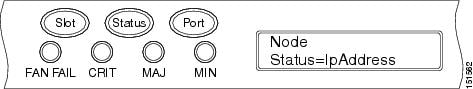
Step 2![]() Repeatedly press the Port button until the following information appears:
Repeatedly press the Port button until the following information appears:
- To change the node IP address, Node Status=IpAddress (Figure 3-2)
- To change the node network mask, Node Status=Net Mask
- To change the default router IP address, Node Status=Default Rtr
Figure 3-2 Selecting the IP Address Option
Step 3![]() Press the Status button to display the node IP address (Figure 3-3), the node subnet mask length, or the default router IP address.
Press the Status button to display the node IP address (Figure 3-3), the node subnet mask length, or the default router IP address.
Figure 3-3 Changing the IP Address
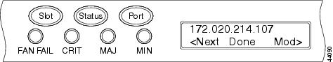
Step 4![]() Push the Slot button to move to the digit of the IP address, subnet mask, or default router that you want to change. The selected digit flashes.
Push the Slot button to move to the digit of the IP address, subnet mask, or default router that you want to change. The selected digit flashes.
Tip The Slot, Status, and Port button positions correspond to the positions of the commands shown on the LCD. For example, in Figure 3-3, you press the Slot button to invoke the Next command and the Status button to invoke the Done command.
Step 5![]() Press the Port button to cycle the IP address, subnet mask, or default router to the correct digit.
Press the Port button to cycle the IP address, subnet mask, or default router to the correct digit.
Step 6![]() When the change is complete, press the Status button to return to the relevant Node Status menu.
When the change is complete, press the Status button to return to the relevant Node Status menu.
Step 7![]() Repeatedly press the Port button until the Shelf Save Configuration option appears (Figure 3-4).
Repeatedly press the Port button until the Shelf Save Configuration option appears (Figure 3-4).
Figure 3-4 Selecting the Save Configuration Option

Step 8![]() Press the Status button to choose the Save Configuration option.
Press the Status button to choose the Save Configuration option.
A Save and REBOOT message appears (Figure 3-5).
Figure 3-5 Saving and Rebooting the TCC2/TCC2P
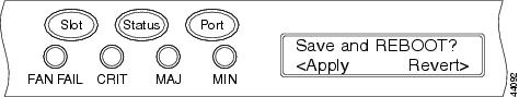
Step 9![]() Press the Slot button to apply the new IP address, subnet mask, or default router configuration or press Port to cancel the configuration.
Press the Slot button to apply the new IP address, subnet mask, or default router configuration or press Port to cancel the configuration.
Note![]() The IP address and default router must be on the same subnet. If not, you cannot apply the configuration.
The IP address and default router must be on the same subnet. If not, you cannot apply the configuration.
Step 10![]() Saving the new configuration causes the TCC2/TCC2P cards to reboot. During the reboot, a “TCC may Reset” message appears on the LCD. The LCD returns to the normal alternating display after both TCC2/TCC2P cards finish rebooting.
Saving the new configuration causes the TCC2/TCC2P cards to reboot. During the reboot, a “TCC may Reset” message appears on the LCD. The LCD returns to the normal alternating display after both TCC2/TCC2P cards finish rebooting.
Step 11![]() Return to your originating procedure (NTP).
Return to your originating procedure (NTP).
DLP-G264 Enable Node Security Mode
Note![]() The node will reboot after you complete this task, causing a temporary disconnection between the CTC computer and the node.
The node will reboot after you complete this task, causing a temporary disconnection between the CTC computer and the node.
Note![]() If an OTS-to-OTS PPC is created between nodes, it will no longer function if the node Security Mode is enabled (see G264 Enable Node Security Mode). The reason for this is that if the Secure mode is enabled, it is no longer possible for the DCN extension feature to use the LAN interface to extend the internal network (due to the network isolation in this configuration mode). The result is that the topology discovery on the OTS-to-OTS PPC no longer operates.
If an OTS-to-OTS PPC is created between nodes, it will no longer function if the node Security Mode is enabled (see G264 Enable Node Security Mode). The reason for this is that if the Secure mode is enabled, it is no longer possible for the DCN extension feature to use the LAN interface to extend the internal network (due to the network isolation in this configuration mode). The result is that the topology discovery on the OTS-to-OTS PPC no longer operates.
Step 1![]() Click the Provisioning > Security > Data Comm tabs.
Click the Provisioning > Security > Data Comm tabs.
Note![]() The security mode options are not available in CTC if TCC2 cards or a mix of TCC2 and TCC2P cards are installed.
The security mode options are not available in CTC if TCC2 cards or a mix of TCC2 and TCC2P cards are installed.
Step 3![]() Review the information on the Change Secure Mode page, then click Next.
Review the information on the Change Secure Mode page, then click Next.
Step 4![]() On the TCC Ethernet Port page, enter the IP address and subnet mask for the TCC2P TCP/IP (LAN) port. The IP address cannot reside on the same subnet as the backplane LAN port or the ONS 15454 default router.
On the TCC Ethernet Port page, enter the IP address and subnet mask for the TCC2P TCP/IP (LAN) port. The IP address cannot reside on the same subnet as the backplane LAN port or the ONS 15454 default router.
Step 6![]() If needed, on the Backplane Ethernet Port page, modify the backplane IP address, subnet mask, and default router. (You normally do not modify these fields if no ONS 15454 network changes have occurred.)
If needed, on the Backplane Ethernet Port page, modify the backplane IP address, subnet mask, and default router. (You normally do not modify these fields if no ONS 15454 network changes have occurred.)
Step 8![]() On the SOCKS Proxy Server Settings page, choose one of the following options:
On the SOCKS Proxy Server Settings page, choose one of the following options:
- External Network Element (ENE) —If selected, the CTC computer is only visible to the ONS 15454 where the CTC computer is connected. The CTC computer is not visible to the nodes connected to the DCC. In addition, firewall is enabled, which means that the node prevents IP traffic from being routed between the DCC and the LAN port.
- Gateway Network Element (GNE) —If selected, the CTC computer is visible to other DCC-connected nodes. The node prevents IP traffic from being routed between the DCC and the LAN port.
Note![]() The SOCKS proxy server is automatically enabled when you enable secure mode.
The SOCKS proxy server is automatically enabled when you enable secure mode.
Within the next 30 to 40 seconds, the TCC2P cards reboot. CTC switches to network view, and the CTC Alerts dialog box appears. In network view, the node changes to gray and a DISCONNECTED condition appears in the Alarms tab.
Step 10![]() In the CTC Alerts dialog box, click Close. Wait for the reboot to finish. (This might take several minutes.)
In the CTC Alerts dialog box, click Close. Wait for the reboot to finish. (This might take several minutes.)
Step 11![]() After the DISCONNECTED condition clears, complete the following steps to suppress the backplane IP address from appearing in CTC and the LCD. If you do not want to suppress the backplane IP address display, continue with Step 12.
After the DISCONNECTED condition clears, complete the following steps to suppress the backplane IP address from appearing in CTC and the LCD. If you do not want to suppress the backplane IP address display, continue with Step 12.
a.![]() Display the node in node view (single-shelf mode) or multishelf view (multishelf mode).
Display the node in node view (single-shelf mode) or multishelf view (multishelf mode).
b.![]() Click the Provisioning > Security > Data Comm tabs.
Click the Provisioning > Security > Data Comm tabs.
c.![]() In the LCD IP Setting field, choose Suppress Display. The IP address will not appear on the ONS 15454 LCD.
In the LCD IP Setting field, choose Suppress Display. The IP address will not appear on the ONS 15454 LCD.
d.![]() Check the Suppress CTC IP Address check box. The IP address will not appear in the CTC information area or the Provisioning > Security > Data Comm tabs.
Check the Suppress CTC IP Address check box. The IP address will not appear in the CTC information area or the Provisioning > Security > Data Comm tabs.
Note![]() After you turn on secure mode, the TCC2P IP address becomes the node IP address.
After you turn on secure mode, the TCC2P IP address becomes the node IP address.
Step 12![]() Return to your originating procedure (NTP).
Return to your originating procedure (NTP).
Step 1![]() In node view (single-shelf mode) or multishelf view (multishelf mode), click the Provisioning > Network tabs.
In node view (single-shelf mode) or multishelf view (multishelf mode), click the Provisioning > Network tabs.
Step 2![]() Click the Static Routing tab. Click Create.
Click the Static Routing tab. Click Create.
Step 3![]() In the Create Static Route dialog box, enter the following:
In the Create Static Route dialog box, enter the following:
- Destination—Enter the IP address of the computer running CTC. To limit access to one computer, enter the full IP address and a subnet mask of 255.255.255.255. To allow access to all computers on the 192.168.1.0 subnet, enter 192.168.1.0 and a subnet mask of 255.255.255.0. You can enter a destination of 0.0.0.0 to allow access to all CTC computers that connect to the router.
- Mask—Enter a subnet mask. If the destination is a host route (that is, one CTC computer), enter a 32-bit subnet mask (255.255.255.255). If the destination is a subnet, adjust the subnet mask accordingly, for example, 255.255.255.0. If the destination is 0.0.0.0, CTC automatically enters a subnet mask of 0.0.0.0 to provide access to all CTC computers. You cannot change this value.
- Next Hop—Enter the IP address of the router port or the node IP address if the CTC computer is connected to the node directly.
- Cost—Enter the number of hops between the ONS 15454 and the computer.
Step 4![]() Click OK. Verify that the static route appears in the Static Route window.
Click OK. Verify that the static route appears in the Static Route window.
Note![]() Static route networking examples are provided in the “Management Network Connectivity” chapter of the Cisco ONS 15454 DWDM Reference Manual.
Static route networking examples are provided in the “Management Network Connectivity” chapter of the Cisco ONS 15454 DWDM Reference Manual.
Step 5![]() Return to your originating procedure (NTP).
Return to your originating procedure (NTP).
DLP-G59 Set Up or Change Open Shortest Path First Protocol
Step 1![]() In node view (single-shelf mode) or multishelf view (multishelf mode), click the Provisioning > Network > OSPF tabs.
In node view (single-shelf mode) or multishelf view (multishelf mode), click the Provisioning > Network > OSPF tabs.
Step 2![]() On the top left side of the OSPF area, complete the following:
On the top left side of the OSPF area, complete the following:
- SDCC Metric—This value is normally unchanged. It sets a cost for sending packets across the Section DCC, which is used by OSPF routers to calculate the shortest path. This value should always be higher than the LAN metric. The default SDCC metric is 100.
- LDCC Metric—Sets a cost for sending packets across the Line DCC. This value should always be lower than the SDCC metric. The default LDCC metric is 33. It is usually not changed.
- RS-DCC Metric—This value is normally unchanged. It sets a cost for sending packets across the regenerator section DCC (RS-DCC), which is used by OSPF routers to calculate the shortest path. This value should always be higher than the LAN metric. The default RS-DCC metric is 100.
- MS-DCC Metric—Sets a cost for sending packets across the multiplex section DCC (MS-DCC). This value should always be lower than the SDCC metric. The default MS-DCC metric is 33. It is usually not changed.
Step 3![]() In the OSPF on LAN area, complete the following:
In the OSPF on LAN area, complete the following:
- OSPF active on LAN—When checked, enables the ONS 15454 OSPF topology to be advertised to OSPF routers on the LAN. Enable this field on ONS 15454 nodes that directly connect to OSPF routers.
- LAN Port Area ID—Enter the OSPF area ID (dotted decimal format) for the router port where the ONS 15454 is connected. (This number is different from the DCC/GCC OSPF Area ID.)
Step 4![]() By default, OSPF is set to No Authentication. If the OSPF router requires authentication, complete the following steps. If not, continue with Step 5.
By default, OSPF is set to No Authentication. If the OSPF router requires authentication, complete the following steps. If not, continue with Step 5.
a.![]() Click the No Authentication button.
Click the No Authentication button.
b.![]() In the Edit Authentication Key dialog box, complete the following:
In the Edit Authentication Key dialog box, complete the following:
- Type—Choose Simple Password.
- Enter Authentication Key—Enter the password.
- Confirm Authentication Key—Enter the same password to confirm it.
The authentication button label changes to Simple Password.
Step 5![]() Provision the OSPF priority and interval settings. The OSPF priority and interval defaults are the defaults most commonly used by OSPF routers. Verify that these defaults match the ones used by the OSPF router where the ONS 15454 is connected.
Provision the OSPF priority and interval settings. The OSPF priority and interval defaults are the defaults most commonly used by OSPF routers. Verify that these defaults match the ones used by the OSPF router where the ONS 15454 is connected.
- Router Priority—Provision the router priority, which determines the designated router for a subnet.
- Hello Interval (sec)—Provision the number of seconds between OSPF hello packet advertisements sent by OSPF routers. Ten seconds is the default.
- Dead Interval—Provision the number of seconds that will pass while an OSPF router’s packets are not visible before its neighbors declare the router down. Forty seconds is the default.
- Transit Delay (sec)—Provision the service speed. One second is the default.
- Retransmit Interval (sec)—Provision the number of seconds that will elapse before a packet is resent. Five seconds is the default.
- LAN Metric—Provision the cost for sending packets across the LAN. This value should always be lower than the SDCC or RS-DCC metric. Ten is the default.
Step 6![]() Under OSPF Area Range Table, create an area range table if one is needed:
Under OSPF Area Range Table, create an area range table if one is needed:
Note![]() Area range tables consolidate the information that is outside an OSPF area border. One ONS 15454 in the ONS 15454 OSPF area is connected to the OSPF router. An area range table on this node points the router to the other nodes that reside within the ONS 15454 OSPF area.
Area range tables consolidate the information that is outside an OSPF area border. One ONS 15454 in the ONS 15454 OSPF area is connected to the OSPF router. An area range table on this node points the router to the other nodes that reside within the ONS 15454 OSPF area.
b.![]() In the Create Area Range dialog box, enter the following:
In the Create Area Range dialog box, enter the following:
- Range Address—Enter the area IP address for the ONS 15454 nodes that reside within the OSPF area. For example, if the ONS 15454 OSPF area includes nodes with IP addresses 10.10.20.100, 10.10.30.150, 10.10.40.200, and 10.10.50.250, the range address would be 10.10.0.0.
- Range Area ID—Enter the OSPF area ID for the ONS 15454 nodes. This is either the ID in the DCC OSPF Area ID field or the ID in the Area ID for LAN Port field.
- Mask Length—Enter the subnet mask length. In the Range Address example, this is 16.
- Advertise—Check this box if you want to advertise the OSPF range table.
Step 7![]() All OSPF areas must be connected to Area 0. If the ONS 15454 OSPF area is not physically connected to Area 0, use the following steps to create a virtual link table that will provide the disconnected area with a logical path to Area 0:
All OSPF areas must be connected to Area 0. If the ONS 15454 OSPF area is not physically connected to Area 0, use the following steps to create a virtual link table that will provide the disconnected area with a logical path to Area 0:
a.![]() Under the OSPF Virtual Link Table, click Create.
Under the OSPF Virtual Link Table, click Create.
b.![]() In the Create Virtual Link dialog box, complete the following fields. OSPF settings must match OSPF settings for the ONS 15454 OSPF area:
In the Create Virtual Link dialog box, complete the following fields. OSPF settings must match OSPF settings for the ONS 15454 OSPF area:
- Neighbor—Enter the router ID of the Area 0 router.
- Transit Delay (sec)—Enter the service speed. One second is the default.
- Hello Int (sec)—Provision the number of seconds between OSPF hello packet advertisements sent by OSPF routers. Ten seconds is the default.
- Auth Type—If the router where the ONS 15454 is connected uses authentication, choose Simple Password. Otherwise, choose No Authentication.
- Retransmit Int (sec)—Provision the time that will elapse, in seconds, before a packet is resent. Five seconds is the default.
- Dead Int (sec)—Provision the number of seconds that will pass while an OSPF router’s packets are not visible before its neighbors declare the router down. Forty seconds is the default.
Step 8![]() After entering the ONS 15454 OSPF area data, click Apply.
After entering the ONS 15454 OSPF area data, click Apply.
If you changed the Area ID, the TCC2/TCC2P cards reset, one at a time. The reset takes approximately 10 to 15 minutes.
Step 9![]() Return to your originating procedure (NTP).
Return to your originating procedure (NTP).
DLP-G60 Set Up or Change Routing Information Protocol
Step 1![]() In node view (single-shelf mode) or multishelf view (multishelf mode), click the Provisioning > Network > RIP tabs.
In node view (single-shelf mode) or multishelf view (multishelf mode), click the Provisioning > Network > RIP tabs.
Step 2![]() Check the RIP Active check box if you are activating RIP.
Check the RIP Active check box if you are activating RIP.
Step 3![]() Choose either RIP Version 1 or RIP Version 2 from the drop-down list, depending on which version is supported in your network.
Choose either RIP Version 1 or RIP Version 2 from the drop-down list, depending on which version is supported in your network.
Step 4![]() Set the RIP metric. The RIP metric can be set to a number between 1 and 15 and represents the number of hops.
Set the RIP metric. The RIP metric can be set to a number between 1 and 15 and represents the number of hops.
Step 5![]() By default, RIP is set to No Authentication. If the router that the ONS 15454 is connected to requires authentication, complete the following steps. If not, continue with Step 6.
By default, RIP is set to No Authentication. If the router that the ONS 15454 is connected to requires authentication, complete the following steps. If not, continue with Step 6.
a.![]() Click the No Authentication button.
Click the No Authentication button.
b.![]() In the Edit Authentication Key dialog box, complete the following:
In the Edit Authentication Key dialog box, complete the following:
- Type—Choose Simple Password.
- Enter Authentication Key—Enter the password.
- Confirm Authentication Key—Enter the same password to confirm it.
The authentication button label changes to Simple Password.
Step 6![]() If you want to complete an address summary, complete the following steps. If not, continue with Step 7. Complete the address summary only if the ONS 15454 is a gateway NE with multiple external ONS 15454 NEs attached with IP addresses in different subnets.
If you want to complete an address summary, complete the following steps. If not, continue with Step 7. Complete the address summary only if the ONS 15454 is a gateway NE with multiple external ONS 15454 NEs attached with IP addresses in different subnets.
a.![]() In the RIP Address Summary area, click Create.
In the RIP Address Summary area, click Create.
b.![]() In the Create Address Summary dialog box, complete the following:
In the Create Address Summary dialog box, complete the following:
- Summary Address—Enter the summary IP address.
- Mask Length—Enter the subnet mask length using the up and down arrows.
- Hops—Enter the number of hops. The smaller the number of hops, the higher the priority.
Step 7![]() Return to your originating procedure (NTP).
Return to your originating procedure (NTP).
NTP-G194 Set Up EMS Secure Access to the ONS 15454
This procedure provisions ONS 15454s and CTC computers for secure access. |
|
Step 1![]() In node view, click the Provisioning > Security > Access pane.
In node view, click the Provisioning > Security > Access pane.
Step 2![]() Under the EMS Access area, change the Access State to Secure.
Under the EMS Access area, change the Access State to Secure.
Step 3![]() Click Apply. The CTC disconnects and reconnects through a secure socket connection.
Click Apply. The CTC disconnects and reconnects through a secure socket connection.
Step 4![]() To create a secure connection, enter https://node-address.
To create a secure connection, enter https://node-address.
Note![]() After setting up a CTC connection in secure mode, http requests are automatically redirected to https mode.
After setting up a CTC connection in secure mode, http requests are automatically redirected to https mode.
Step 5![]() A first time connection is authenticated by the Website Certification is Not Known dialog box. Accept the certificate and click OK. The Security Error: Domain Name Mismatch dialog box appears. Click OK to continue.
A first time connection is authenticated by the Website Certification is Not Known dialog box. Accept the certificate and click OK. The Security Error: Domain Name Mismatch dialog box appears. Click OK to continue.
Stop. You have completed this procedure.
NTP-G341 Set Up Secure Access to the ONS 15454 TL1
This procedure provisions ONS 15454s for secure access to TL1. |
|
Step 1![]() In the node view, click the Provisioning > Security > Access pane.
In the node view, click the Provisioning > Security > Access pane.
Step 2![]() Under the TL1 Access area, change the Access State to Secure.
Under the TL1 Access area, change the Access State to Secure.
Existing non-secure TL1 sessions, if any, are terminated.
Step 4![]() To create a secure TL1 connection, enter the following command at the UNIX or Linux prompt:
To create a secure TL1 connection, enter the following command at the UNIX or Linux prompt:
ssh -l username node-ip -p port-number
The port number for secure TL1 is 4083.
Note![]() Use any SSH client on Windows.
Use any SSH client on Windows.
Stop. You have completed this procedure.
NTP-G27 Set Up the ONS 15454 for Firewall Access
This procedure provisions ONS 15454 nodes and CTC computers for access through firewalls. |
|
IIOP listener port number provided by your LAN or firewall administrator |
|
Step 1![]() Log into a node that is behind the firewall. See the G46 Log into CTC for instructions. If you are already logged in, continue with Step 2.
Log into a node that is behind the firewall. See the G46 Log into CTC for instructions. If you are already logged in, continue with Step 2.
Step 2![]() If the ONS 15454 node is in a protected network and the CTC computer is in an external network, complete the G61 Provision the IIOP Listener Port on the ONS 15454.
If the ONS 15454 node is in a protected network and the CTC computer is in an external network, complete the G61 Provision the IIOP Listener Port on the ONS 15454.
Figure 3-6 shows ONS 15454 nodes in a protected network and the CTC computer in an external network. For the computer to access the ONS 15454 nodes, you must provision the IIOP listener port specified by your firewall administrator on the ONS 15454.
Figure 3-6 Nodes Behind a Firewall
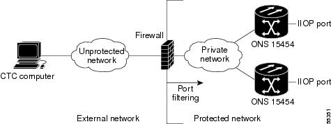
Step 3![]() If the CTC computer resides behind a firewall, complete the G62 Provision the IIOP Listener Port on the CTC Computer.
If the CTC computer resides behind a firewall, complete the G62 Provision the IIOP Listener Port on the CTC Computer.
Figure 3-7 shows a CTC computer and ONS 15454 behind firewalls. For the computer to access the ONS 15454, you must provision the IIOP port on the CTC computer and on the ONS 15454.
Figure 3-7 CTC Computer and ONS 15454 Nodes Residing Behind Firewalls
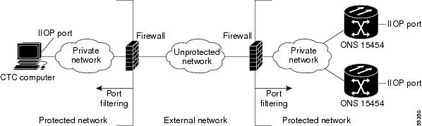
Stop. You have completed this procedure.
This procedure provisions an FTP Host that you can use to perform database backup and restore or software download to an End Network Element (ENE) when proxy or firewall is enabled. |
|
Step 1![]() Complete the G46 Log into CTC. If you are already logged in, continue with Step 2.
Complete the G46 Log into CTC. If you are already logged in, continue with Step 2.
Step 2![]() If you want to turn on the ONS 15454 secure mode, which allows two IPv4 addresses to be provisioned for the node if TCC2P cards are installed, complete the G264 Enable Node Security Mode. Refer to the “Management Network Connectivity” chapter in the Cisco ONS 15454 SDH Reference Manual for information about secure mode.
If you want to turn on the ONS 15454 secure mode, which allows two IPv4 addresses to be provisioned for the node if TCC2P cards are installed, complete the G264 Enable Node Security Mode. Refer to the “Management Network Connectivity” chapter in the Cisco ONS 15454 SDH Reference Manual for information about secure mode.
Step 3![]() In Node view, click the Provisioning > Network > FTP Hosts tabs.
In Node view, click the Provisioning > Network > FTP Hosts tabs.
Step 5![]() Enter a valid IP address in the FTP Host Address field. A maximum of 12 host can be entered.
Enter a valid IP address in the FTP Host Address field. A maximum of 12 host can be entered.
Note![]() In ONS 15454 Software Release 9.0 and later, you can configure an IPv6 address for an FTP server, in addition to an IPv4 address.
In ONS 15454 Software Release 9.0 and later, you can configure an IPv6 address for an FTP server, in addition to an IPv4 address.
Step 6![]() The Mask is automatically set according to the Net/Subnet Mask length specified in “G56 Provision IP Settings” section. To change the Mask, click the Up/Down arrows on the Length menu.
The Mask is automatically set according to the Net/Subnet Mask length specified in “G56 Provision IP Settings” section. To change the Mask, click the Up/Down arrows on the Length menu.
Step 7![]() Check the FTP Relay Enable radio button to allow FTP commands at the GNE relay. If you will enable the relay at a later time, go to Step 9. Certain TL1 commands executed on an ENE require FTP access into the Data Communication Network (DCN), the FTP relay on the GNE provides this access. The FTP hosts that you have configured in CTC can be used with the TL1 COPY-RFILE (for database backup and restore or software download) or COPY-IOSCFG (for Cisco IOS Configuration File backup and restore) commands.
Check the FTP Relay Enable radio button to allow FTP commands at the GNE relay. If you will enable the relay at a later time, go to Step 9. Certain TL1 commands executed on an ENE require FTP access into the Data Communication Network (DCN), the FTP relay on the GNE provides this access. The FTP hosts that you have configured in CTC can be used with the TL1 COPY-RFILE (for database backup and restore or software download) or COPY-IOSCFG (for Cisco IOS Configuration File backup and restore) commands.
Step 8![]() Enter the time, in minutes, that FTP Relay will be enabled. A valid entry is a number between 0 and 60. The number 0 disallows FTP command relay. After the specified time has elapsed the FTP Relay Enable flag is unset and FTP command relay is disallowed.
Enter the time, in minutes, that FTP Relay will be enabled. A valid entry is a number between 0 and 60. The number 0 disallows FTP command relay. After the specified time has elapsed the FTP Relay Enable flag is unset and FTP command relay is disallowed.
Step 10![]() Repeat Step 4 through Step 9 to provision additional FTP Hosts.
Repeat Step 4 through Step 9 to provision additional FTP Hosts.
Stop. You have completed this procedure.
DLP-G61 Provision the IIOP Listener Port on the ONS 15454
Note![]() If the Enable SOCKS proxy on port 1080 check box is checked, CTC will use Port 1080 and ignore the configured IIOP port setting. If the check box is later unchecked, the configured IIOP listener port will be used.
If the Enable SOCKS proxy on port 1080 check box is checked, CTC will use Port 1080 and ignore the configured IIOP port setting. If the check box is later unchecked, the configured IIOP listener port will be used.
Step 1![]() In node view (single-shelf mode) or multishelf view (multishelf mode), click the Provisioning > Security > Access tabs.
In node view (single-shelf mode) or multishelf view (multishelf mode), click the Provisioning > Security > Access tabs.
Step 2![]() In the TCC CORBA (IIOP) Listener Port area, choose a listener port option:
In the TCC CORBA (IIOP) Listener Port area, choose a listener port option:
- Default - TCC Fixed —Uses Port 57790 to connect to ONS 15454 nodes on the same side of the firewall or if no firewall is used (default). This option can be used for access through a firewall if Port 57790 is available.
- Standard Constant —Uses Port 683, the Common Object Request Broker Architecture (CORBA) default port number.
- Other Constant —If Port 683 is not used, type the IIOP port specified by your firewall administrator.
Step 4![]() When the Change Network Configuration message appears, click Yes.
When the Change Network Configuration message appears, click Yes.
Both ONS 15454 TCC2/TCC2P cards reboot, one at a time. The reboot takes approximately 15 minutes.
Step 5![]() Return to your originating procedure (NTP).
Return to your originating procedure (NTP).
DLP-G62 Provision the IIOP Listener Port on the CTC Computer
This task selects the IIOP listener port for CTC and must be completed if the computer running CTC resides behind a firewall. |
|
IIOP listener port number from LAN or firewall administrator |
|
Step 1![]() From the Edit menu, choose Preferences.
From the Edit menu, choose Preferences.
Step 2![]() In the Preferences dialog box, click the Firewall tab.
In the Preferences dialog box, click the Firewall tab.
Step 3![]() In the CTC CORBA (IIOP) Listener Port area, choose a listener port option:
In the CTC CORBA (IIOP) Listener Port area, choose a listener port option:
Step 4![]() Click Apply. A warning appears telling you that the port change will apply during the next CTC login.
Click Apply. A warning appears telling you that the port change will apply during the next CTC login.
Step 6![]() In the Preferences dialog box, click OK.
In the Preferences dialog box, click OK.
Step 7![]() To access the ONS 15454 using the IIOP port, log out of CTC then log back in. (To log out, choose Exit from the File menu).
To access the ONS 15454 using the IIOP port, log out of CTC then log back in. (To log out, choose Exit from the File menu).
Step 8![]() Return to your originating procedure (NTP).
Return to your originating procedure (NTP).
Note![]() This procedure requires provisioning of non-ONS equipment including routers and third party NEs. Do not begin until you have the capability to complete that provisioning.
This procedure requires provisioning of non-ONS equipment including routers and third party NEs. Do not begin until you have the capability to complete that provisioning.
Step 1![]() Complete the G46 Log into CTC at the node where you want to provision the OSI. If you are already logged in, continue with Step 2.
Complete the G46 Log into CTC at the node where you want to provision the OSI. If you are already logged in, continue with Step 2.
Step 2![]() As needed, complete the following tasks:
As needed, complete the following tasks:
- G283 Provision OSI Routing Mode—Complete this task first.
- G284 Provision the TARP Operating Parameters—Complete this task second.
- G285 Add a Static TID-to-NSAP Entry to the TARP Data Cache—Complete this task as needed.
- G287 Add a TARP Manual Adjacency Table Entry—Complete this task as needed.
- G288 Provision OSI Routers—Complete this task as needed.
- G289 Provision Additional Manual Area Addresses—Complete this task as needed.
- G290 Enable the OSI Subnet on the LAN Interface—Complete this task as needed.
- G291 Create an IP-Over-CLNS Tunnel—Complete this task as needed.
Stop. You have completed this procedure.
DLP-G283 Provision OSI Routing Mode
This task provisions the OSI routing mode. Complete this task when the ONS 15454 is connected to networks with third party NEs that use the OSI protocol stack for DCN communication. |
|
Note![]() For ONS 15454 nodes, three virtual routers can be provisioned. The node primary Network Service Access Point (NSAP) address is also the Router 1 primary manual area address. To edit the primary NSAP, you must edit the Router 1 primary manual area address. After you enable Router 1 on the Routers subtab, the Change Primary Area Address button is available to edit the address.
For ONS 15454 nodes, three virtual routers can be provisioned. The node primary Network Service Access Point (NSAP) address is also the Router 1 primary manual area address. To edit the primary NSAP, you must edit the Router 1 primary manual area address. After you enable Router 1 on the Routers subtab, the Change Primary Area Address button is available to edit the address.
Step 1![]() In node view (single-shelf mode) or multishelf view (multishelf mode), click the Provisioning > OSI tabs.
In node view (single-shelf mode) or multishelf view (multishelf mode), click the Provisioning > OSI tabs.
- End System —The ONS 15454 performs OSI end system (ES) functions and relies upon an intermediate system (IS) for communication with nodes that reside within its OSI area.
Note![]() The End System routing mode is not available if more than one virtual router is enabled.
The End System routing mode is not available if more than one virtual router is enabled.
- I ntermediate System Level 1 —The ONS 15454 performs OSI IS functions. It communicates with IS and ES nodes that reside within its OSI area. It depends upon an IS L1/L2 node to communicate with IS and ES nodes that reside outside its OSI area.
- Intermediate System Level 1/Level 2 —The ONS 15454 performs IS functions. It communicates with IS and ES nodes that reside within its OSI area. It also communicates with IS L1/L2 nodes that reside in other OSI areas. Before choosing this option, verify the following:
–![]() The node is connected to another IS Level 1/Level 2 node that resides in a different OSI area.
The node is connected to another IS Level 1/Level 2 node that resides in a different OSI area.
–![]() The node is connected to all nodes within its area that are provisioned as IS L1/L2.
The node is connected to all nodes within its area that are provisioned as IS L1/L2.
Step 3![]() If needed, change the LSP data buffers:
If needed, change the LSP data buffers:
- L1 LSP Buffer Size—Adjusts the Level 1 link state protocol data unit (PDU) buffer size. The default is 512. It should not be changed.
- L2 LSP Buffer Size—Adjusts the Level 2 link state PDU buffer size. The default is 512. It should not be changed.
Step 4![]() Return to your originating procedure (NTP).
Return to your originating procedure (NTP).
DLP-G284 Provision the TARP Operating Parameters
This task provisions the TARP operating parameters including TARP PDU propagation, timers, and loop detection buffer (LDB). |
|
Step 1![]() In node view (single-shelf mode) or multishelf view (multishelf mode), click the Provisioning > OSI > TARP > Config tabs.
In node view (single-shelf mode) or multishelf view (multishelf mode), click the Provisioning > OSI > TARP > Config tabs.
Step 2![]() Provision the following parameters, as needed:
Provision the following parameters, as needed:
- TARP PDUs L1 Propagation—If checked (default), TARP Type 1 PDUs that are received by the node and are not excluded by the LDB are propagated to other NEs within the Level 1 OSI area. (Type 1 PDUs request a protocol address that matches a target identifier [TID] within a Level 1 routing area.) The propagation does not occur if the NE is the target of the Type 1 PDU, and PDUs are not propagated to the NE from which the PDU was received.
Note![]() The TARP PDUs L1 Propagation parameter is not used when the Node Routing Area (on the Provisioning > OSI > Main Setup tab) is set to End System.
The TARP PDUs L1 Propagation parameter is not used when the Node Routing Area (on the Provisioning > OSI > Main Setup tab) is set to End System.
- TARP PDUs L2 Propagation—If checked (default), TARP Type 2 PDUs that are received by the node and are not excluded by the LDB are propagated to other NEs within the Level 2 OSI areas. (Type 2 PDUs request a protocol address that matches a TID within a Level 2 routing area.) The propagation occurs if the NE is not the target of the Type 2 PDU, and PDUs are not propagated to the NE from which the PDU was received.
Note![]() The TARP PDUs L2 Propagation parameter is only used when the Node Routing Area is provisioned to Intermediate System Level 1/Level 2.
The TARP PDUs L2 Propagation parameter is only used when the Node Routing Area is provisioned to Intermediate System Level 1/Level 2.
–![]() TID-to-NSAP resolution requests (originate TARP Type 1 and Type 2 PDUs)
TID-to-NSAP resolution requests (originate TARP Type 1 and Type 2 PDUs)
–![]() NSAP-to-TID requests (originate Type 5 PDUs)
NSAP-to-TID requests (originate Type 5 PDUs)
–![]() TARP address changes (originate Type 4 PDUs)
TARP address changes (originate Type 4 PDUs)
Note![]() TARP Echo and NSAP to TID are not supported.
TARP Echo and NSAP to TID are not supported.
- TARP Data Cache—If checked (default), the node maintains a TARP data cache (TDC). The TDC is a database of TID-to-NSAP pairs created from TARP Type 3 PDUs received by the node and modified by TARP Type 4 PDUs (TID-to-NSAP updates or corrections). TARP 3 PDUs are responses to Type 1 and Type 2 PDUs. The TDC can also be populated with static entries entered on the TARP > Static TDC tab.
Note![]() TARP Data Cache is only used when the TARP PDUs Origination parameter is enabled.
TARP Data Cache is only used when the TARP PDUs Origination parameter is enabled.
Note![]() The L2 TARP Data Cache parameter is designed for Intermediate System Level 1/Level 2 nodes that are connected to other Intermediate System Level 1/Level 2 nodes. Enabling the parameter for Intermediate System Level 1 nodes is not recommended.
The L2 TARP Data Cache parameter is designed for Intermediate System Level 1/Level 2 nodes that are connected to other Intermediate System Level 1/Level 2 nodes. Enabling the parameter for Intermediate System Level 1 nodes is not recommended.
Note![]() The LDB parameter is not used if the Node Routing Mode is provisioned to End System or if the TARP PDUs L1 Propagation parameter is not enabled.
The LDB parameter is not used if the Node Routing Mode is provisioned to End System or if the TARP PDUs L1 Propagation parameter is not enabled.
- LAN TARP Storm Suppression—If checked (default), enables TARP storm suppression. This function prevents redundant TARP PDUs from being unnecessarily propagated across the LAN network.
- Send Type 4 PDU on Startup—If checked, a TARP Type 4 PDU is originated during the initial ONS 15454 startup. Type 4 PDUs indicate that a TID or NSAP change has occurred at the NE. (The default setting is not enabled.)
- Type 4 PDU Delay—Sets the amount of time that will pass before the Type 4 PDU is generated when Send Type 4 PDU on Startup is enabled. 60 seconds is the default. The range is 0 to 255 seconds.
Note![]() The Send Type 4 PDU on Startup and Type 4 PDU Delay parameters are not used if TARP PDUs Origination is not enabled.
The Send Type 4 PDU on Startup and Type 4 PDU Delay parameters are not used if TARP PDUs Origination is not enabled.
- LDB Entry—Sets the TARP loop detection buffer timer. The loop detection buffer time is assigned to each LDB entry for which the TARP sequence number (tar-seq) is zero. The default is 5 minutes. The range is 1 to 10 minutes.
- LDB Flush—Sets the frequency period for flushing the LDB. The default is 5 minutes. The range is 0 to 1440 minutes.
- T1—Sets the amount of time to wait for a response to a Type 1 PDU. Type 1 PDUs seek a specific NE TID within an OSI Level 1 area. The default is 15 seconds. The range is 0 to 3600 seconds.
- T2—Sets the amount of time to wait for a response to a Type 2 PDU. TARP Type 2 PDUs seek a specific NE TID value within OSI Level 1 and Level 2 areas. The default is 25 seconds. The range is 0 to 3600 seconds.
- T3—Sets the amount of time to wait for an address resolution request. The default is 40 seconds. The range is 0 to 3600 seconds.
- T4—Sets the amount of time to wait for an error recovery. This timer begins after the T2 timer expires without finding the requested NE TID. The default is 20 seconds. The range is 0 to 3600 seconds.
Note![]() The T1, T2, and T4 timers are not used if the TARP PDUs Origination check box is not checked.
The T1, T2, and T4 timers are not used if the TARP PDUs Origination check box is not checked.
Step 4![]() Return to your originating procedure (NTP).
Return to your originating procedure (NTP).
DLP-G285 Add a Static TID-to-NSAP Entry to the TARP Data Cache
Step 1![]() In node view (single-shelf mode) or multishelf view (multishelf mode), click the Provisioning > OSI > TARP > Static TDC tabs.
In node view (single-shelf mode) or multishelf view (multishelf mode), click the Provisioning > OSI > TARP > Static TDC tabs.
Step 2![]() Click Add Static Entry.
Click Add Static Entry.
Step 3![]() In the Add Static Entry dialog box, enter the following:
In the Add Static Entry dialog box, enter the following:
- TID—Enter the TID of the NE. (For ONS nodes, the TID is the Node Name parameter on the node or multishelf view Provisioning > General tab.)
- NSAP—Enter the OSI NSAP address in the NSAP field or, if preferred, click Use Mask and enter the address in the Masked NSAP Entry dialog box.
Step 4![]() Click OK to close the Masked NSAP Entry dialog box, if used, and then click OK to close the Add Static Entry dialog box.
Click OK to close the Masked NSAP Entry dialog box, if used, and then click OK to close the Add Static Entry dialog box.
Step 5![]() Return to your originating procedure (NTP).
Return to your originating procedure (NTP).
DLP-G287 Add a TARP Manual Adjacency Table Entry
This task adds an entry to the TARP manual adjacency table (MAT). Entries are added to the MAT when the ONS 15454 must communicate across routers or NEs that lack TARP capability. |
|
Step 1![]() In node view (single-shelf mode) or multishelf view (multishelf mode), click the Provisioning > OSI > TARP > MAT tabs.
In node view (single-shelf mode) or multishelf view (multishelf mode), click the Provisioning > OSI > TARP > MAT tabs.
Step 3![]() In the Add TARP Manual Adjacency Table Entry dialog box, enter the following:
In the Add TARP Manual Adjacency Table Entry dialog box, enter the following:
–![]() Level 1 —Indicates that the adjacency is within the same area as the current node. The entry generates Type 1 PDUs.
Level 1 —Indicates that the adjacency is within the same area as the current node. The entry generates Type 1 PDUs.
–![]() Level 2 —Indicates that the adjacency is in a different area than the current node. The entry generates Type 2 PDUs.
Level 2 —Indicates that the adjacency is in a different area than the current node. The entry generates Type 2 PDUs.
- NSAP—Enter the OSI NSAP address in the NSAP field or, if preferred, click Use Mask and enter the address in the Masked NSAP Entry dialog box.
Step 4![]() Click OK to close the Masked NSAP Entry dialog box, if used, and then click OK to close the Add Static Entry dialog box.
Click OK to close the Masked NSAP Entry dialog box, if used, and then click OK to close the Add Static Entry dialog box.
Step 5![]() Return to your originating procedure (NTP).
Return to your originating procedure (NTP).
DLP-G288 Provision OSI Routers
This task enables an OSI router and edits its primary manual area address. |
|
Note![]() Router 1 must be enabled before you can enable and edit the primary manual area addresses for Routers 2 and 3.
Router 1 must be enabled before you can enable and edit the primary manual area addresses for Routers 2 and 3.
Note![]() The Router 1 manual area address, System ID, and Selector “00” create the node NSAP address. Changing the Router 1 manual area address changes the node NSAP address.
The Router 1 manual area address, System ID, and Selector “00” create the node NSAP address. Changing the Router 1 manual area address changes the node NSAP address.
Note![]() The System ID for Router 1 is the node MAC address. The System IDs for Routers 2 and 3 are created by adding 1 and 2 respectively to the Router 1 System ID. You cannot edit the System IDs.
The System ID for Router 1 is the node MAC address. The System IDs for Routers 2 and 3 are created by adding 1 and 2 respectively to the Router 1 System ID. You cannot edit the System IDs.
Step 1![]() Click the Provisioning > OSI > Routers > Setup tabs.
Click the Provisioning > OSI > Routers > Setup tabs.
Step 2![]() Chose the router you want provision and click Edit. The OSI Router Editor dialog box appears.
Chose the router you want provision and click Edit. The OSI Router Editor dialog box appears.
Step 3![]() In the OSI Router Editor dialog box:
In the OSI Router Editor dialog box:
a.![]() Check Enable Router to enable the router and make its primary area address available for editing.
Check Enable Router to enable the router and make its primary area address available for editing.
b.![]() Click the manual area address, then click Edit.
Click the manual area address, then click Edit.
c.![]() In the Edit Manual Area Address dialog box, edit the primary area address in the Area Address field. If you prefer, click Use Mask and enter the edits in the Masked NSAP Entry dialog box. The address (hexadecimal format) can be 8 to 24 alphanumeric characters (0–9, a–f) in length.
In the Edit Manual Area Address dialog box, edit the primary area address in the Area Address field. If you prefer, click Use Mask and enter the edits in the Masked NSAP Entry dialog box. The address (hexadecimal format) can be 8 to 24 alphanumeric characters (0–9, a–f) in length.
d.![]() Click OK successively to close the following dialog boxes: Masked NSAP Entry (if used), Edit Manual Area Address, and OSI Router Editor.
Click OK successively to close the following dialog boxes: Masked NSAP Entry (if used), Edit Manual Area Address, and OSI Router Editor.
Step 4![]() Return to your originating procedure (NTP).
Return to your originating procedure (NTP).
DLP-G289 Provision Additional Manual Area Addresses
This task provisions the OSI manual area addresses. One primary area and two additional manual areas can be created for each virtual router. |
|
Step 1![]() Click the Provisioning > OSI > Routers > Setup tabs.
Click the Provisioning > OSI > Routers > Setup tabs.
Step 2![]() Chose the router where you want provision an additional manual area address and click Edit. The OSI Router Editor dialog box appears.
Chose the router where you want provision an additional manual area address and click Edit. The OSI Router Editor dialog box appears.
Step 3![]() In the OSI Router Editor dialog box:
In the OSI Router Editor dialog box:
a.![]() Check Enable Router to enable the router and make its primary area address available for editing.
Check Enable Router to enable the router and make its primary area address available for editing.
b.![]() Click the manual area address, then click Add.
Click the manual area address, then click Add.
c.![]() In the Add Manual Area Address dialog box, enter the primary area address in the Area Address field. If you prefer, click Use Mask and enter the address in the Masked NSAP Entry dialog box. The address (hexadecimal format) can be 2 to 24 alphanumeric characters (0–9, a–f) in length.
In the Add Manual Area Address dialog box, enter the primary area address in the Area Address field. If you prefer, click Use Mask and enter the address in the Masked NSAP Entry dialog box. The address (hexadecimal format) can be 2 to 24 alphanumeric characters (0–9, a–f) in length.
d.![]() Click OK successively to close the following dialog boxes: Masked NSAP Entry (if used), Add Manual Area Address, and OSI Router Editor.
Click OK successively to close the following dialog boxes: Masked NSAP Entry (if used), Add Manual Area Address, and OSI Router Editor.
Step 4![]() Return to your originating procedure (NTP).
Return to your originating procedure (NTP).
DLP-G290 Enable the OSI Subnet on the LAN Interface
This task enables the OSI subnetwork point of attachment on the LAN interface. |
|
Note![]() When you create communication channels (optical service channel [OSC] or generic communications channel [GCC]), OSI subnetwork points of attachment are enabled on the communication channels. See the G38 Provision OSC Terminations and the G76 Provision DCC/GCC Terminations.
When you create communication channels (optical service channel [OSC] or generic communications channel [GCC]), OSI subnetwork points of attachment are enabled on the communication channels. See the G38 Provision OSC Terminations and the G76 Provision DCC/GCC Terminations.
Note![]() The OSI subnetwork point of attachment cannot be enabled for the LAN interface if the OSI routing mode is set to ES.
The OSI subnetwork point of attachment cannot be enabled for the LAN interface if the OSI routing mode is set to ES.
Note![]() If secure mode is on, the OSI subnet is enabled on the backplane LAN port, not the front TCC2P TCP/IP (LAN) port.
If secure mode is on, the OSI subnet is enabled on the backplane LAN port, not the front TCC2P TCP/IP (LAN) port.
Step 1![]() Click the Provisioning > OSI > Routers > Subnet tabs.
Click the Provisioning > OSI > Routers > Subnet tabs.
Step 2![]() Click Enable LAN Subnet.
Click Enable LAN Subnet.
Step 3![]() In the Enable LAN Subnet dialog box, complete the following fields:
In the Enable LAN Subnet dialog box, complete the following fields:
- ESH—Sets the End System Hello (ESH) propagation frequency. An ES NE transmits ESHs to inform other ESs and ISs about the NSAPs it serves. The default is 10 seconds. The range is 10 to 1000 seconds.
- ISH—Sets the Intermediate System Hello (ISH) PDU propagation frequency. An intermediate system NE sends ISHs to other ESs and ISs to inform them about the IS NEs it serves. The default is 10 seconds. The range is 10 to 1000 seconds.
- IIH—Sets the Intermediate System to Intermediate System Hello (IIH) PDU propagation frequency. The IS-IS Hello PDUs establish and maintain adjacencies between ISs. The default is 3 seconds. The range is 1 to 600 seconds.
- IS-IS Cost—Sets the cost for sending packets on the LAN subnet. The IS-IS protocol uses the cost to calculate the shortest routing path. The default IS-IS cost for LAN subnets is 20. It normally should not be changed.
- DIS Priority—Sets the designated intermediate system (DIS) priority. In IS-IS networks, one router is elected to serve as the DIS (LAN subnets only). Cisco router DIS priority is 64. For the ONS 15454 LAN subnet, the default DIS priority is 63. It normally should not be changed.
Step 5![]() Return to your originating procedure (NTP).
Return to your originating procedure (NTP).
DLP-G291 Create an IP-Over-CLNS Tunnel
This task creates an IP-over-CLNS tunnel to allow ONS 15454 nodes to communicate across equipment and networks that use the OSI protocol stack. |
|
Step 1![]() Click the Provisioning > OSI > Tunnels tabs.
Click the Provisioning > OSI > Tunnels tabs.
Step 3![]() In the Create IP Over CLNS Tunnel dialog box, complete the following fields:
In the Create IP Over CLNS Tunnel dialog box, complete the following fields:
–![]() Cisco —Creates the proprietary Cisco IP tunnel. Cisco IP tunnels add the CLNS header to the IP packets.
Cisco —Creates the proprietary Cisco IP tunnel. Cisco IP tunnels add the CLNS header to the IP packets.
–![]() GRE —Creates a generic routing encapsulation (GRE) tunnel. GRE tunnels add the CLNS header and a GRE header to the IP packets.
GRE —Creates a generic routing encapsulation (GRE) tunnel. GRE tunnels add the CLNS header and a GRE header to the IP packets.
The Cisco proprietary tunnel is slightly more efficient than the GRE tunnel because it does not add the GRE header to each IP packet. The two tunnel types are not compatible. Most Cisco routers support the Cisco IP tunnel, while only a few support both GRE and Cisco IP tunnels. You generally should create Cisco IP tunnels if you are tunneling between two Cisco routers or between a Cisco router and an ONS node.
- IP Address—Enter the IP address of the IP-over-CLNS tunnel destination.
- IP Mask—Enter the IP address subnet mask of the IP-over-CLNS destination.
- OSPF Metric—Enter the OSPF metric for sending packets across the IP-over-CLNS tunnel. The OSPF metric, or cost, is used by OSPF routers to calculate the shortest path. The default is 110. Normally, it is not be changed unless you are creating multiple tunnel routes and want to prioritize routing by assigning different metrics.
- NSAP Address—Enter the destination NE or OSI router NSAP address.
Step 5![]() Provision the other tunnel endpoint using the documentation provided by the manufacturer of the third party vendor NE.
Provision the other tunnel endpoint using the documentation provided by the manufacturer of the third party vendor NE.
Step 6![]() Return to your originating procedure (NTP).
Return to your originating procedure (NTP).
This procedure provisions the SNMP parameters so that you can use SNMP management software with the ONS 15454. |
|
Step 1![]() Complete the G46 Log into CTC at the node where you want to set up SNMP. If you are already logged in, continue with Step 2.
Complete the G46 Log into CTC at the node where you want to set up SNMP. If you are already logged in, continue with Step 2.
Step 2![]() In node view (single-shelf mode) or multishelf view (multishelf mode), click the Provisioning > SNMP tabs.
In node view (single-shelf mode) or multishelf view (multishelf mode), click the Provisioning > SNMP tabs.
Step 3![]() In the Trap Destinations area, click Create.
In the Trap Destinations area, click Create.
Step 4![]() Complete the following in the Create SNMP Trap Destination dialog box (Figure 3-8):
Complete the following in the Create SNMP Trap Destination dialog box (Figure 3-8):
Note![]() In ONS 15454 DWDM Software Release 9.0 and later, you can configure IPv6 addresses for SNMPv2/v3 trap destinations and SNMPv3 proxy targets, in addition to IPv4 addresses.
In ONS 15454 DWDM Software Release 9.0 and later, you can configure IPv6 addresses for SNMPv2/v3 trap destinations and SNMPv3 proxy targets, in addition to IPv4 addresses.
Note![]() The community name is a form of authentication and access control. The community name assigned to the ONS 15454 is case-sensitive and must match the community name of the NMS.
The community name is a form of authentication and access control. The community name assigned to the ONS 15454 is case-sensitive and must match the community name of the NMS.
Figure 3-8 Creating an SNMP Trap
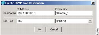
Step 5![]() Click OK. The node IP address of the node where you provisioned the new trap destination appears in the Trap Destinations area.
Click OK. The node IP address of the node where you provisioned the new trap destination appears in the Trap Destinations area.
Step 6![]() Click the node IP address in the Trap Destinations area. Verify the SNMP information that appears in the Selected Destination list.
Click the node IP address in the Trap Destinations area. Verify the SNMP information that appears in the Selected Destination list.
Step 7![]() If you want the SNMP agent to accept SNMP SET requests on certain MIBs, click the Allow SNMP Sets check box. If this box is not checked, SET requests are rejected.
If you want the SNMP agent to accept SNMP SET requests on certain MIBs, click the Allow SNMP Sets check box. If this box is not checked, SET requests are rejected.
Step 8![]() If you want to set up the SNMP proxy feature to allow network management, message reporting, and performance statistic retrieval across ONS firewalls, click the Allow SNMP Proxy check box located on the SNMP tab.
If you want to set up the SNMP proxy feature to allow network management, message reporting, and performance statistic retrieval across ONS firewalls, click the Allow SNMP Proxy check box located on the SNMP tab.
Note![]() The Use Generic MIB check box is normally not checked for MSTP. It is checked only when the ONS 15454 resides in networks with multiple ONS products, and the network management system requires MIBs with the same name to have the same object IDs. By default, the ONS 15454 uses the CERENT-454-MIBs. Other ONS products, such as the ONS 15600, the ONS 15327, and ONS 15310-CL, use the CERENT-GENERIC-MIBs. If Use Generic MIB is checked, the ONS 15454 will use the CERENT-GENERIC-MIBs so the object IDs will be the same for all products.
The Use Generic MIB check box is normally not checked for MSTP. It is checked only when the ONS 15454 resides in networks with multiple ONS products, and the network management system requires MIBs with the same name to have the same object IDs. By default, the ONS 15454 uses the CERENT-454-MIBs. Other ONS products, such as the ONS 15600, the ONS 15327, and ONS 15310-CL, use the CERENT-GENERIC-MIBs. If Use Generic MIB is checked, the ONS 15454 will use the CERENT-GENERIC-MIBs so the object IDs will be the same for all products.
Note![]() Using the ONS firewall proxy feature effectively breaches the ONS firewall to exchange management information.
Using the ONS firewall proxy feature effectively breaches the ONS firewall to exchange management information.
For more information about the SNMP proxy feature, refer to the “SNMP” chapter in the Cisco ONS 15454 DWDM Reference Manual.
Step 10![]() If you are setting up SNMP proxies, you can set up to three relays that send SNMP trap error counts back to the NE for each trap destination address:
If you are setting up SNMP proxies, you can set up to three relays that send SNMP trap error counts back to the NE for each trap destination address:
a.![]() Click the first trap destination IP address. The address and its community name appear in the Destination fields.
Click the first trap destination IP address. The address and its community name appear in the Destination fields.
b.![]() Enter up to three SNMP Proxy relay addresses and community names in the fields for Relay A, Relay B, and Relay C.
Enter up to three SNMP Proxy relay addresses and community names in the fields for Relay A, Relay B, and Relay C.
Note![]() The community names specified for each relay node must match one of the provisioned SNMP community names in the NE.
The community names specified for each relay node must match one of the provisioned SNMP community names in the NE.
Note![]() The SNMP proxy directs SNMP traps from this node through Relay A to Relay B to Relay C to the trap destination. Ensure that you enter the IP addresses in the correct order so that this sequence runs correctly.
The SNMP proxy directs SNMP traps from this node through Relay A to Relay B to Relay C to the trap destination. Ensure that you enter the IP addresses in the correct order so that this sequence runs correctly.
Stop. You have completed this procedure.
NTP-G143 Import the Cisco TransportPlanner NE Update Configuration File
Note![]() The Cisco TransportPlanner configuration file contains parameters for the node, shelf, card type, port (including the card’s wavelength), pluggable port module (PPM), as well as OTN and FEC parameters. Only the values present in XML format appear in the configuration file parameters; if the values are not in XML format, a column appears blank. The XML file values are independently reported and do not affect any configuration changes that you apply.
The Cisco TransportPlanner configuration file contains parameters for the node, shelf, card type, port (including the card’s wavelength), pluggable port module (PPM), as well as OTN and FEC parameters. Only the values present in XML format appear in the configuration file parameters; if the values are not in XML format, a column appears blank. The XML file values are independently reported and do not affect any configuration changes that you apply.
Step 1![]() Complete the G46 Log into CTC at the node where you want to import the Cisco TransportPlanner configuration file. If you are already logged in, continue with Step 2.
Complete the G46 Log into CTC at the node where you want to import the Cisco TransportPlanner configuration file. If you are already logged in, continue with Step 2.
Step 2![]() If you choose the Provision Node Layout option to preprovision the cards in the shelf, complete the following steps. If not, continue with Step 3.
If you choose the Provision Node Layout option to preprovision the cards in the shelf, complete the following steps. If not, continue with Step 3.
a.![]() Display the node in node view (single-shelf mode) or multishelf view (multishelf mode).
Display the node in node view (single-shelf mode) or multishelf view (multishelf mode).
b.![]() Verify that the common control cards (TCC2/TCC2P, AIC-I and MSC-ISC) cards are the only cards installed. If in single or multishelf mode, verify that each shelf in the multishelf has two TCC2/TCC2P cards.
Verify that the common control cards (TCC2/TCC2P, AIC-I and MSC-ISC) cards are the only cards installed. If in single or multishelf mode, verify that each shelf in the multishelf has two TCC2/TCC2P cards.
- If common control cards are the only cards installed, continue with Step 3.
- If other cards appear, continue with Step c .
c.![]() If a physical card other than thecommon control cards is installed, remove it from the shelf.
If a physical card other than thecommon control cards is installed, remove it from the shelf.
d.![]() If preprovisioned DWDM cards are present, delete them using the G351 Delete a Card in CTC, then repeat Steps a and b .
If preprovisioned DWDM cards are present, delete them using the G351 Delete a Card in CTC, then repeat Steps a and b .
Step 3![]() If you have not created a log file to record the results of the NE update, complete the following steps. If a log file has been created, continue with Step 4.
If you have not created a log file to record the results of the NE update, complete the following steps. If a log file has been created, continue with Step 4.
a.![]() Open a text editor or word processing application.
Open a text editor or word processing application.
b.![]() Create a new text (TXT) document with a file name of your choosing.
Create a new text (TXT) document with a file name of your choosing.
c.![]() Save the text document in a directory that is easy to navigate to from CTC.
Save the text document in a directory that is easy to navigate to from CTC.
Step 4![]() In CTC node view (single-shelf mode) or multishelf view, click the Provisioning > WDM-ANS > Node Setup tabs.
In CTC node view (single-shelf mode) or multishelf view, click the Provisioning > WDM-ANS > Node Setup tabs.
Step 5![]() In the field under Select XML file, type the path to the Cisco TransportPlanner node setup file containing the parameters for the network where your node resides, or click Browse and navigate to the file on your computer or network server. Click the file, then click Open. The file will have an XML extension.
In the field under Select XML file, type the path to the Cisco TransportPlanner node setup file containing the parameters for the network where your node resides, or click Browse and navigate to the file on your computer or network server. Click the file, then click Open. The file will have an XML extension.
Step 6![]() In the field under Select Log file, type the path to the text file that you created in Step 3, or click Browse and navigate to the file on your computer or a network server where you want the node setup results recorded.
In the field under Select Log file, type the path to the text file that you created in Step 3, or click Browse and navigate to the file on your computer or a network server where you want the node setup results recorded.
Note![]() The log file records parameters that were updated successfully and provides an explanation of why an update could not be completed. Each node setup session overwrites the log file contents. If you want to save the results from a previous NE update, save the log file with new name.
The log file records parameters that were updated successfully and provides an explanation of why an update could not be completed. Each node setup session overwrites the log file contents. If you want to save the results from a previous NE update, save the log file with new name.
Step 8![]() When the Node Setup Selection for Node-Name page appears, complete the following steps. If not, continue with Step 9
When the Node Setup Selection for Node-Name page appears, complete the following steps. If not, continue with Step 9![]() .
.
a.![]() Choose the node profile that you want to apply to the node. The Cisco TransportPlanner XML file contains profiles for all nodes in the network. Choose the profile that applies to the node you are provisioning.
Choose the node profile that you want to apply to the node. The Cisco TransportPlanner XML file contains profiles for all nodes in the network. Choose the profile that applies to the node you are provisioning.
Step 9![]() On the Node Setup for node name page, choose one or more of the following:
On the Node Setup for node name page, choose one or more of the following:
- Node Layout—Preprovisions the slots in CTC for the cards required by the network plan. Choose this option when no DWDM cards are installed. (Errors will occur if cards are installed or the slots are preprovisioned.) Preprovisioning the slots before the physical cards are installed ensures that card installers place the cards in the correct slots. Preprovisioning the slots is also useful if you want to set up the network prior to card installation.
- Card Parameters—If checked, provisions the following parameters, if the cards are installed.
–![]() TXP, MXP, GE_XP, 10GE_XP, GE_XPE, 10GE_XPE, ADM-10G, and OTU2_XP cards—Provisions the OTN and FEC parameters.
TXP, MXP, GE_XP, 10GE_XP, GE_XPE, 10GE_XPE, ADM-10G, and OTU2_XP cards—Provisions the OTN and FEC parameters.
–![]() OPT-AMP-L, OPT-AMP-17-C, OPT-AMP-C, GE_XP, 10GE_XP, GE_XPE, and 10GE_XPE cards—Provisions the card mode.
OPT-AMP-L, OPT-AMP-17-C, OPT-AMP-C, GE_XP, 10GE_XP, GE_XPE, and 10GE_XPE cards—Provisions the card mode.
–![]() PSM cards—Provisions the optical switching thresholds for the W-RX and P-RX ports.
PSM cards—Provisions the optical switching thresholds for the W-RX and P-RX ports.
- Pluggable Port Modules— If checked, allows the provisioning of PPMs on TXP, MXP, GE_XP, 10GE_XP, GE_XPE, 10GE_XPE, ADM-10G, and OTU2_XP cards, including PPM payloads.
- Internal Patchcords—If checked, allows creation of internal patchcords among cards provisioned in the node.
- Optical Sides—If checked, allows the provisioning of optical sides.
- ANS Parameters—If checked, installs the ANS parameters. ANS parameters provision the values required for the node to function within the specified network design. ANS parameters include span losses, optical power, optics thresholds, amplifier working mode, gain, tilt, and many others. Refer to the “Node Reference” chapter in the Cisco ONS 15454 DWDM Reference Manual for a list of ONS 15454 ANS parameters.
Note![]() If you are importing the Cisco TransportPlanner configuration file for the first time, you normally choose all available options.
If you are importing the Cisco TransportPlanner configuration file for the first time, you normally choose all available options.
Step 10![]() Click Next. If you chose Skip Interactive Mode, continue with Step 11
Click Next. If you chose Skip Interactive Mode, continue with Step 11![]() . If not, the wizard page that appears depends on the options chosen in Step 9: Complete the steps shown in Table 3-2 for each option.
. If not, the wizard page that appears depends on the options chosen in Step 9: Complete the steps shown in Table 3-2 for each option.
|
|
|
|---|---|
View the cards and slots on the left side of the page and verify that they are the same as the layout in the Cisco TransportPlanner Shelf Layout (see Table 3-1). If the cards and slots match, click Apply. If not, click Cancel. and contact your next level of support to verify that you have the correct node setup file. If the site has a multishelf configuration, click Next and repeat this step for each shelf at the site. CTC preprovisions the slots. (This might take a few seconds.) The results appear in the Log window. Slots that are successfully provisioned display an “Applied” status. A “Slot not empty” status appears if slots cannot be provisioned because a card is physically installed or the slot is already provisioned. If this occurs, complete the following steps. Otherwise, continue with the next NE Update function. 1. 2. 3. – –
Note |
|
1. |
|
1. |
|
1. c. |
Step 11![]() Click Finish, then click OK in the Wizard Complete confirmation dialog box.
Click Finish, then click OK in the Wizard Complete confirmation dialog box.
Note![]() Common control cards are not provisioned by Cisco TransportPlanner.
Common control cards are not provisioned by Cisco TransportPlanner.
Stop. You have completed this procedure.
This task deletes a card from an ONS 15454 slot that is provisioned in CTC. |
|
Note![]() It is recommended that the card be physically removed from its slot before deleting it from CTC.
It is recommended that the card be physically removed from its slot before deleting it from CTC.
Step 1![]() Verify that the following conditions are not present. (During node turn-up, these conditions are normally not present):
Verify that the following conditions are not present. (During node turn-up, these conditions are normally not present):
- The card is a TCC2/TCC2P card.
- The card is part of a protection group.
- The card has optical channels or overhead circuits provisioned.
- The card is being used for timing.
- The card has an OSC/GCC termination.
- A port on the card is being used for a Link Management Protocol (LMP) channel or link.
- The card is part of an optical side.
- The card is assigned to DWDM patchcords.
- If a port on the card is in service.
- If a port on the card is part of a circuit.
If any of these conditions exist, do not continue. You will not be able to delete the card until the card is removed from protection groups; circuits, DCC, and GCCs are deleted; a different timing source is provisioned, and the LMP link or channel is deleted.
- To replace a TCC2/TCC2P card, refer to the Cisco ONS 15454 DWDM Troubleshooting Guide.
- To delete a protection group, see the G83 Modify or Delete Card Protection Settings.
- To delete optical channels see the G347 Delete Optical Channel Client Connections and the G106 Delete Optical Channel Network Connections; to delete overhead circuits, see the G112 Delete Overhead Circuits.
- To remove the card as a timing source, see the G87 Change Node Timing Parameters.
- To remove OSC or GCC terminations, see the G85 Modify or Delete OSC Terminations, DCC/GCC Terminations, and Provisionable Patchcords.
- To delete LMP channels or links, see G164 Configure Link Management Protocol.
- To remove a DWDM patchcord, see the G355 Delete an Internal Patchcord.
- To remove an optical side, see the G480 Delete an Optical Side.
Step 2![]() On the shelf graphic in CTC, right-click the card that you want to remove and choose Delete Card.
On the shelf graphic in CTC, right-click the card that you want to remove and choose Delete Card.
Note![]() A deleted card no longer reboots and reappears in CTC after R5.0.
A deleted card no longer reboots and reappears in CTC after R5.0.
Step 3![]() Return to your originating procedure (NTP).
Return to your originating procedure (NTP).
DLP-G353 Preprovision a Single Slot
This task preprovisions a single ONS 15454 slot in CTC. Preprovisioning of all the slots in the shelf is normally performed when you complete the G143 Import the Cisco TransportPlanner NE Update Configuration File. Use this task if you need to manually preprovision a single slot. All slot preprovisioning must be based upon the Cisco TransportPlanner shelf layout prepared for your site. |
|
Step 1![]() In node view (single-shelf mode) or multishelf view (multishelf mode), right-click an empty slot where you will install a card.
In node view (single-shelf mode) or multishelf view (multishelf mode), right-click an empty slot where you will install a card.
Step 2![]() From the Add Card shortcut menu, choose the card type that will be installed based on the Cisco TransportPlanner shelf layout (see Table 3-1). Only cards that can be installed in the slot appear in the Add Card shortcut menu. The OPT-AMP-L, 32WSS, 32MUX-O, and 32DMX-O cards require two vacant slots, or they will not appear in the shortcut menu. Table 3-3 shows the Add Card shortcut menu items and submenu items, and the card groups and menu options/cards that they reference.
From the Add Card shortcut menu, choose the card type that will be installed based on the Cisco TransportPlanner shelf layout (see Table 3-1). Only cards that can be installed in the slot appear in the Add Card shortcut menu. The OPT-AMP-L, 32WSS, 32MUX-O, and 32DMX-O cards require two vacant slots, or they will not appear in the shortcut menu. Table 3-3 shows the Add Card shortcut menu items and submenu items, and the card groups and menu options/cards that they reference.
|
|
|
|
|
|
|
|---|---|---|---|---|---|
Note![]() When you preprovision a slot, the card appears purple in the CTC shelf graphic (the card appears as white when a card is installed in the slot). NP on the card graphic indicates that the card is not physically installed.
When you preprovision a slot, the card appears purple in the CTC shelf graphic (the card appears as white when a card is installed in the slot). NP on the card graphic indicates that the card is not physically installed.
Step 3![]() Repeat Step 2 until all the cards shown in the Cisco TransportPlanner shelf layout are provisioned in CTC.
Repeat Step 2 until all the cards shown in the Cisco TransportPlanner shelf layout are provisioned in CTC.
Stop. You have completed this procedure.
NTP-G320 Configure the Node as a Non-DWDM Network
Step 1![]() In node view (single-shelf mode) or multishelf view (multishelf mode), click the Provisioning > WDM-ANS > Provisioning tabs.
In node view (single-shelf mode) or multishelf view (multishelf mode), click the Provisioning > WDM-ANS > Provisioning tabs.
Step 2![]() From the Selector area, select Network Type.
From the Selector area, select Network Type.
Step 3![]() Choose Not-DWDM, from the Value drop-down list. Click Apply.
Choose Not-DWDM, from the Value drop-down list. Click Apply.
Step 4![]() In node view (single-shelf mode) or multishelf view (multishelf mode), click the Provisioning > WDM-ANS > Port Status tabs.
In node view (single-shelf mode) or multishelf view (multishelf mode), click the Provisioning > WDM-ANS > Port Status tabs.
Step 5![]() Click the Launch ANS button. The relevant ports in the node will be in IS state.
Click the Launch ANS button. The relevant ports in the node will be in IS state.
Step 7![]() Return to your originating procedure (NTP).
Return to your originating procedure (NTP).
DLP-G693 Configure the Amplifier
This task configures the optical parameters and threshold values of the amplifier card. |
|
Step 1![]() Display the amplifier card in card view.
Display the amplifier card in card view.
Step 2![]() Click the Provisioning > Card tabs.
Click the Provisioning > Card tabs.
Step 3![]() Select the working mode from the Card Working Mode drop-down list.
Select the working mode from the Card Working Mode drop-down list.
Step 4![]() Change to node view (single-shelf mode) or multishelf view (multishelf mode), then click the Provisioning > WDM-ANS > Provisioning tabs.
Change to node view (single-shelf mode) or multishelf view (multishelf mode), then click the Provisioning > WDM-ANS > Provisioning tabs.
Step 5![]() From the Selector area, select the amplifier slot. If the default parameters are present, continue with Step 6. If not, click Add to add the Channel LOS Threshold, Amplifier Tilt, Power, and Amplifier Working Mode parameters. To add the ANS parameters, see the “DLP-G541 Add an ANS Parameter” task on page 14-60 for instructions.
From the Selector area, select the amplifier slot. If the default parameters are present, continue with Step 6. If not, click Add to add the Channel LOS Threshold, Amplifier Tilt, Power, and Amplifier Working Mode parameters. To add the ANS parameters, see the “DLP-G541 Add an ANS Parameter” task on page 14-60 for instructions.
Step 6![]() Click the value of the ANS parameter that you want to modify and enter the new value specified in Table 3-4. To modify the ANS parameters, see the “DLP-G681 Modify an ANS Parameter” task on page 14-61 for instructions.
Click the value of the ANS parameter that you want to modify and enter the new value specified in Table 3-4. To modify the ANS parameters, see the “DLP-G681 Modify an ANS Parameter” task on page 14-61 for instructions.
|
|
|
|
|---|---|---|
Step 8![]() Click the Provisioning > WDM-ANS > Port Status tabs.
Click the Provisioning > WDM-ANS > Port Status tabs.
Step 10![]() In the Apply Launch ANS dialog box, click Yes.
In the Apply Launch ANS dialog box, click Yes.
Step 11![]() In the Launch ANS confirmation dialog box, click OK.
In the Launch ANS confirmation dialog box, click OK.
Step 12![]() In node view (single-shelf mode) or multishelf view (multishelf mode), click the Provisioning > WDM-ANS > Provisioning tabs.
In node view (single-shelf mode) or multishelf view (multishelf mode), click the Provisioning > WDM-ANS > Provisioning tabs.
Step 13![]() Verify the following in the Results column:
Verify the following in the Results column:
Step 14![]() Verify that the Set By column displays t he value “ANS” or “APC” as the application that sets the ANS parameter.
Verify that the Set By column displays t he value “ANS” or “APC” as the application that sets the ANS parameter.
Step 15![]() Return to your originating procedure (NTP).
Return to your originating procedure (NTP).
Step 1![]() In node view (single-shelf mode) or multishelf view (multishelf mode), click the Provisioning > WDM-ANS > Provisioning tabs.
In node view (single-shelf mode) or multishelf view (multishelf mode), click the Provisioning > WDM-ANS > Provisioning tabs.
Step 2![]() From the Selector area, select the PSM slot. If the default parameters are present, continue with Step 3. If not, click Add to add the Channel LOS Threshold and VOA Attenuation parameters. To add the ANS parameters, see the “DLP-G541 Add an ANS Parameter” task on page 14-60 for instructions.
From the Selector area, select the PSM slot. If the default parameters are present, continue with Step 3. If not, click Add to add the Channel LOS Threshold and VOA Attenuation parameters. To add the ANS parameters, see the “DLP-G541 Add an ANS Parameter” task on page 14-60 for instructions.
Step 3![]() Click the value of the ANS parameter that you want to modify and enter the new value specified in Table 3-4. To modify the ANS parameters, see the “DLP-G681 Modify an ANS Parameter” task on page 14-61 for instructions.
Click the value of the ANS parameter that you want to modify and enter the new value specified in Table 3-4. To modify the ANS parameters, see the “DLP-G681 Modify an ANS Parameter” task on page 14-61 for instructions.
|
|
|
|
|---|---|---|
Step 5![]() Click the Provisioning > WDM-ANS > Port Status tabs.
Click the Provisioning > WDM-ANS > Port Status tabs.
Step 7![]() In the Apply Launch ANS dialog box, click Yes.
In the Apply Launch ANS dialog box, click Yes.
Step 8![]() In the Launch ANS confirmation dialog box, click OK.
In the Launch ANS confirmation dialog box, click OK.
Step 9![]() In node view (single-shelf mode) or multishelf view (multishelf mode), click the Provisioning > WDM-ANS > Provisioning tabs.
In node view (single-shelf mode) or multishelf view (multishelf mode), click the Provisioning > WDM-ANS > Provisioning tabs.
Step 10![]() Verify the following in the Results column:
Verify the following in the Results column:
Step 11![]() Verify that the Set By column displays t he value “ANS” or “APC” as the application that sets the ANS parameter.
Verify that the Set By column displays t he value “ANS” or “APC” as the application that sets the ANS parameter.
Step 12![]() Return to your originating procedure (NTP).
Return to your originating procedure (NTP).
NTP-G30 Install the DWDM Cards
This procedure describes how to install the DWDM multiplexer, demultiplexer, wavelength selective switch, wavelength cross-connect, OADM, OSC, PSM, and optical amplifier cards. |
|
Cisco TransportPlanner shelf layout The following C-band or L-band cards, as required by your site plan:
The ONS 15454 NE defaults file if the node will use custom NE defaults |
|
G15 Install the Common Control Cards G139 Verify Cisco TransportPlanner Reports and Files G143 Import the Cisco TransportPlanner NE Update Configuration File |
|

Warning![]() This warning symbol means danger. You are in a situation that could cause bodily injury. Before you work on any equipment, be aware of the hazards involved with electrical circuitry and be familiar with standard practices for preventing accidents. To see translations of the warnings that appear in this publication, refer to the Regulatory Compliance and Safety Information document for the appropriate Cisco chassis. Statement 274
This warning symbol means danger. You are in a situation that could cause bodily injury. Before you work on any equipment, be aware of the hazards involved with electrical circuitry and be familiar with standard practices for preventing accidents. To see translations of the warnings that appear in this publication, refer to the Regulatory Compliance and Safety Information document for the appropriate Cisco chassis. Statement 274
Warning![]() During this procedure, wear grounding wrist straps to avoid ESD damage to the card. Do not directly touch the backplane with your hand or any metal tool, or you could shock yourself. Statement 94
During this procedure, wear grounding wrist straps to avoid ESD damage to the card. Do not directly touch the backplane with your hand or any metal tool, or you could shock yourself. Statement 94
Warning![]() Class I (CDRH) and Class 1M (IEC) laser products. Statement 1055
Class I (CDRH) and Class 1M (IEC) laser products. Statement 1055
Warning![]() Invisible laser radiation may be emitted from the end of the unterminated fiber cable or connector. Do not view directly with optical instruments. Viewing the laser output with certain optical instruments (for example, eye loupes, magnifiers, and microscopes) within a distance of 100 mm may pose an eye hazard. Statement 1056
Invisible laser radiation may be emitted from the end of the unterminated fiber cable or connector. Do not view directly with optical instruments. Viewing the laser output with certain optical instruments (for example, eye loupes, magnifiers, and microscopes) within a distance of 100 mm may pose an eye hazard. Statement 1056
Warning![]() High-performance devices on this card can get hot during operation. To remove the card, hold it by the faceplate and bottom edge. Allow the card to cool before touching any other part of it or before placing it in an antistatic bag. Statement 201
High-performance devices on this card can get hot during operation. To remove the card, hold it by the faceplate and bottom edge. Allow the card to cool before touching any other part of it or before placing it in an antistatic bag. Statement 201
Note![]() For United States installations, complies with the United States Federal Drug Administration Code of Federal Regulations Title 21, Sections 1040.10 and 1040.11, except for deviations pursuant to Laser Notice No. 50, dated July 26, 2001.
For United States installations, complies with the United States Federal Drug Administration Code of Federal Regulations Title 21, Sections 1040.10 and 1040.11, except for deviations pursuant to Laser Notice No. 50, dated July 26, 2001.
Note![]() If protective clips are installed on the backplane connectors of the cards, remove the clips before installing the cards.
If protective clips are installed on the backplane connectors of the cards, remove the clips before installing the cards.
Note![]() If you install a card incorrectly, the FAIL LED flashes continuously.
If you install a card incorrectly, the FAIL LED flashes continuously.
Step 1![]() If the node requires a custom NE default settings to be installed on the node, complete the G136 Import Network Element Defaults. If not, continue with Step 2. (For information about the ONS 15454 NE defaults, refer to the “Network Elements Defaults” appendix in the Cisco ONS 15454 DWDM Reference Manual.)
If the node requires a custom NE default settings to be installed on the node, complete the G136 Import Network Element Defaults. If not, continue with Step 2. (For information about the ONS 15454 NE defaults, refer to the “Network Elements Defaults” appendix in the Cisco ONS 15454 DWDM Reference Manual.)
Step 2![]() Verify that you have one of the following guides for the DWDM card installation:
Verify that you have one of the following guides for the DWDM card installation:
- The slots that were preprovisioned when you completed the G143 Import the Cisco TransportPlanner NE Update Configuration File.
- The Cisco TransportPlanner shelf layout report (see Table 3-1).
Step 3![]() If the slots are preprovisioned, continue with Step 4. If you are using the Cisco TransportPlanner shelf layout report, complete the G348 Use the Cisco TransportPlanner Shelf Layout Report.
If the slots are preprovisioned, continue with Step 4. If you are using the Cisco TransportPlanner shelf layout report, complete the G348 Use the Cisco TransportPlanner Shelf Layout Report.
Step 4![]() Remove a DWDM card from its packaging, then remove the protective caps from the backplane connectors. (Safety caps are typically yellow.)
Remove a DWDM card from its packaging, then remove the protective caps from the backplane connectors. (Safety caps are typically yellow.)
Step 5![]() Open the card latches/ejectors.
Open the card latches/ejectors.
Step 6![]() Use the latches/ejectors to firmly slide the card along the slot guide rails until the card plugs into the receptacle at the back of the slot. The correct slot is designated by the Cisco TransportPlanner shelf layout.
Use the latches/ejectors to firmly slide the card along the slot guide rails until the card plugs into the receptacle at the back of the slot. The correct slot is designated by the Cisco TransportPlanner shelf layout.
Step 7![]() Verify that the card is inserted correctly. Simultaneously close the latches/ejectors on the card.
Verify that the card is inserted correctly. Simultaneously close the latches/ejectors on the card.
Note![]() It is possible to close the latches/ejectors when the card is not completely plugged in. Ensure that you cannot insert the card any further.
It is possible to close the latches/ejectors when the card is not completely plugged in. Ensure that you cannot insert the card any further.
After installing the card, the following LED activity will occur:
Step 8![]() If the card does not boot up properly, or the LED activity is not similar to the activity in Step 7, check the following:
If the card does not boot up properly, or the LED activity is not similar to the activity in Step 7, check the following:
- When a physical card type does not match the type of card provisioned for that slot in CTC, the card might not boot. If a DWDM card does not boot, open CTC and ensure that the slot is not provisioned for a different card type before assuming that the card is faulty.
- If the red FAIL LED does not turn on, check the power.
- If you insert a card into a slot provisioned for a different card, all LEDs turn off and a minor equipment mismatch alarm appears on the CTC Alarms tab.
- If the red FAIL LED is on continuously or the LEDs behave erratically, the card is not installed.
If any of conditions are present, remove the card and repeat Steps 4 to 7 . If the card does not boot up properly the second time, it might be defective. Contact your next level of support.
Step 9![]() Repeat Steps 5 through 8 until all the DWDM cards are installed in the node.
Repeat Steps 5 through 8 until all the DWDM cards are installed in the node.
Step 10![]() If an OPT-PRE card (or the OPT-AMP-L, OPT-AMP-17-C, or OPT-AMP-C card in OPT-PRE card mode) are installed, complete one of the following steps for each OPT-PRE card based on the Cisco TransportPlanner shelf layout. If an OPT-PRE is not installed, you have completed this procedure.
If an OPT-PRE card (or the OPT-AMP-L, OPT-AMP-17-C, or OPT-AMP-C card in OPT-PRE card mode) are installed, complete one of the following steps for each OPT-PRE card based on the Cisco TransportPlanner shelf layout. If an OPT-PRE is not installed, you have completed this procedure.
- If the Cisco TransportPlanner shelf layout does not include DCUs, install a patchcord and 4-dB attenuator with a tolerance of +/–1 dB between the OPT-PRE or OPT-AMP-L DC TX and RX ports for each OPT-PRE or OPT-AMP-L card installed in the shelf.
- If the shelf layout includes DCUs, complete the G31 Install the DWDM Dispersion Compensating Units for each side of the shelf that requires a DCU.
Stop. You have completed this procedure.
DLP-G348 Use the Cisco TransportPlanner Shelf Layout Report
This task describes how to use the Cisco TransportPlanner shelf layout report to install cards in a DWDM node. |
|
Step 1![]() Display the Cisco TransportPlanner shelf layout report for your site. The report can be viewed in Cisco TransportPlanner (see Figure 3-9). It can also be viewed as a JPEG graphic. Refer to the Cisco TransportPlanner DWDM Operations Guide for information about generating shelf layout reports.
Display the Cisco TransportPlanner shelf layout report for your site. The report can be viewed in Cisco TransportPlanner (see Figure 3-9). It can also be viewed as a JPEG graphic. Refer to the Cisco TransportPlanner DWDM Operations Guide for information about generating shelf layout reports.
Figure 3-9 Cisco TransportPlanner Shelf Layout Report Displayed in Cisco TransportPlanner
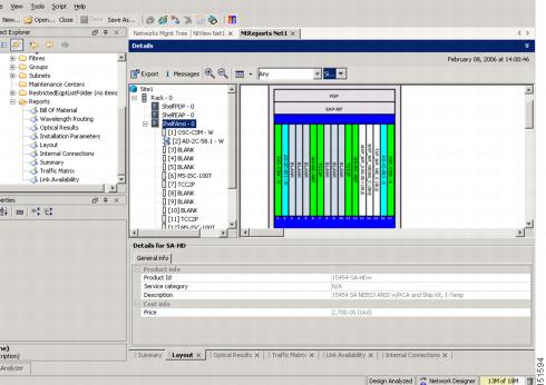
Step 2![]() Review the following installation information:
Review the following installation information:
–![]() Flex Shelf—The ONS 15216 FlexLayer mechanical shelf houses Y-cable modules. Flex shelf positions are numbered 1 to 4 from left to right.
Flex Shelf—The ONS 15216 FlexLayer mechanical shelf houses Y-cable modules. Flex shelf positions are numbered 1 to 4 from left to right.
–![]() DCU Shelf—The Cisco ONS 15216 dispersion compensation shelf assembly houses DCUs. DCU positions are numbered 1 to 2 from left to right.
DCU Shelf—The Cisco ONS 15216 dispersion compensation shelf assembly houses DCUs. DCU positions are numbered 1 to 2 from left to right.
–![]() Shelf-ANSI- n or Shelf-ETSI- n —The ONS 15454 shelf assembly houses ONS 15454 common, DWDM, and client cards. Positions in this type of shelf are numbered 1 to 17 from left to right. Multiple shelves might appear.
Shelf-ANSI- n or Shelf-ETSI- n —The ONS 15454 shelf assembly houses ONS 15454 common, DWDM, and client cards. Positions in this type of shelf are numbered 1 to 17 from left to right. Multiple shelves might appear.
–![]() Unit Name (Product ID)— Identifies the card by its Product ID.
Unit Name (Product ID)— Identifies the card by its Product ID.
–![]() Unit Description—Identifies the card by its name.
Unit Description—Identifies the card by its name.
Step 3![]() Return to your originating procedure (NTP).
Return to your originating procedure (NTP).
NTP-G31 Install the DWDM Dispersion Compensating Units
This procedure describes how to install the DCUs for DWDM shelves. |
|
Warning![]() Class I (CDRH) and Class 1M (IEC) laser products. Statement 1055
Class I (CDRH) and Class 1M (IEC) laser products. Statement 1055
Warning![]() Invisible laser radiation may be emitted from the end of the unterminated fiber cable or connector. Do not view directly with optical instruments. Viewing the laser output with certain optical instruments (for example, eye loupes, magnifiers, and microscopes) within a distance of 100 mm may pose an eye hazard. Statement 1056
Invisible laser radiation may be emitted from the end of the unterminated fiber cable or connector. Do not view directly with optical instruments. Viewing the laser output with certain optical instruments (for example, eye loupes, magnifiers, and microscopes) within a distance of 100 mm may pose an eye hazard. Statement 1056
Note![]() For US installations, complies with the US Federal Drug Administration Code of Federal Regulations Title 21, Sections 1040.10 and 1040.11, except for deviations pursuant to Laser Notice No. 50, dated July 26, 2001.
For US installations, complies with the US Federal Drug Administration Code of Federal Regulations Title 21, Sections 1040.10 and 1040.11, except for deviations pursuant to Laser Notice No. 50, dated July 26, 2001.
Step 1![]() Remove the DCU from its packaging, then remove the protective caps from the connectors. (Safety caps are typically yellow.)
Remove the DCU from its packaging, then remove the protective caps from the connectors. (Safety caps are typically yellow.)
Step 2![]() Use both hands to push the DCU all the way into the chassis until the connector spring lock on the right side of the module clicks into place.
Use both hands to push the DCU all the way into the chassis until the connector spring lock on the right side of the module clicks into place.
Step 3![]() Open the cover with the laser warning on the connector adapter and then connect the cable connector.
Open the cover with the laser warning on the connector adapter and then connect the cable connector.
Note![]() The Side A DCU is commonly installed on the left side and the Side B DCU is commonly installed on the right side.
The Side A DCU is commonly installed on the left side and the Side B DCU is commonly installed on the right side.
Note![]() Double-check the placement of the DCU card(s) with your Cisco TransportPlanner shelf layout. If you install the wrong DCU in a slot, remove the DCU and install the correct one.
Double-check the placement of the DCU card(s) with your Cisco TransportPlanner shelf layout. If you install the wrong DCU in a slot, remove the DCU and install the correct one.
Stop. You have completed this procedure.
NTP-G179 Install the TXP, MXP, GE_XP, 10GE_XP, GE_XPE, 10GE_XPE, ADM-10G, and OTU2_XP Cards
Warning![]() During this procedure, wear grounding wrist straps to avoid ESD damage to the card. Do not directly touch the backplane with your hand or any metal tool, or you could shock yourself. Statement 94
During this procedure, wear grounding wrist straps to avoid ESD damage to the card. Do not directly touch the backplane with your hand or any metal tool, or you could shock yourself. Statement 94
Warning![]() Class 1 laser product. Statement 1008
Class 1 laser product. Statement 1008
Warning![]() Invisible laser radiation may be emitted from the end of the unterminated fiber cable or connector. Do not view directly with optical instruments. Viewing the laser output with certain optical instruments (for example, eye loupes, magnifiers, and microscopes) within a distance of 100 mm may pose an eye hazard. Statement 1056
Invisible laser radiation may be emitted from the end of the unterminated fiber cable or connector. Do not view directly with optical instruments. Viewing the laser output with certain optical instruments (for example, eye loupes, magnifiers, and microscopes) within a distance of 100 mm may pose an eye hazard. Statement 1056
Warning![]() Class I (CDRH) and Class 1M (IEC) laser products. Statement 1055
Class I (CDRH) and Class 1M (IEC) laser products. Statement 1055
Note![]() For US installations, complies with the US Federal Drug Administration Code of Federal Regulations Title 21, Sections 1040.10 and 1040.11, except for deviations pursuant to Laser Notice No. 50, dated July 26, 2001.
For US installations, complies with the US Federal Drug Administration Code of Federal Regulations Title 21, Sections 1040.10 and 1040.11, except for deviations pursuant to Laser Notice No. 50, dated July 26, 2001.
Note![]() If protective clips are installed on the backplane connectors of the cards, remove the clips before installing the cards.
If protective clips are installed on the backplane connectors of the cards, remove the clips before installing the cards.
Note![]() If you install a card incorrectly, the FAIL LED flashes continuously.
If you install a card incorrectly, the FAIL LED flashes continuously.
Step 1![]() Display the Cisco TransportPlanner shelf layout (see Table 3-1) for the node where you will install the card.
Display the Cisco TransportPlanner shelf layout (see Table 3-1) for the node where you will install the card.
Step 2![]() Remove the card from its packaging, then remove the protective clips from the backplane connectors.
Remove the card from its packaging, then remove the protective clips from the backplane connectors.
Step 3![]() Open the card latches/ejectors.
Open the card latches/ejectors.
Step 4![]() Use the latches/ejectors to firmly slide the card along the guide rails until the card plugs into the receptacle at the back of the slot designated by the Cisco TransportPlanner shelf layout.
Use the latches/ejectors to firmly slide the card along the guide rails until the card plugs into the receptacle at the back of the slot designated by the Cisco TransportPlanner shelf layout.
Step 5![]() Verify that the card is inserted correctly and simultaneously close the latches/ejectors on the card.
Verify that the card is inserted correctly and simultaneously close the latches/ejectors on the card.
Note![]() It is possible to close the latches and ejectors when the card is not completely plugged into the backplane. Ensure that you cannot insert the card any further.
It is possible to close the latches and ejectors when the card is not completely plugged into the backplane. Ensure that you cannot insert the card any further.
Note![]() If you install the card in the wrong slot, CTC will raise a MEA (EQPT) alarm. To clear this alarm, open the latches, slide the card out, then insert it in the correct slot.
If you install the card in the wrong slot, CTC will raise a MEA (EQPT) alarm. To clear this alarm, open the latches, slide the card out, then insert it in the correct slot.
After you install the card, the FAIL, ACT, and SF LEDs will go through a sequence of activities. They will turn on, turn off, and blink at different points. After approximately 2 to 3 minutes, the ACT or ACT/STBY LED turns on. The SF LED might persist until all card ports connect to their far-end counterparts and a signal is present.
Note![]() Until a card is provisioned, the card is in the standby condition and the ACT/STBY LED remains amber in color.
Until a card is provisioned, the card is in the standby condition and the ACT/STBY LED remains amber in color.
Step 6![]() If the card does not boot up properly or the LEDs do not progress through the activities described in Step 5, check the following:
If the card does not boot up properly or the LEDs do not progress through the activities described in Step 5, check the following:
- When a physical card type does not match the type of card provisioned for that slot in CTC, the card might not boot and CTC will show a MEA (EQPT) alarm. If the card does not boot, open CTC and ensure that the slot is not provisioned for a different card type before assuming that the card is faulty.
- If the red FAIL LED does not turn on, check the power.
- If you insert a card into a slot provisioned for a different card, all LEDs turn off.
- If the red FAIL LED is on continuously or the LEDs behave erratically, the card is not installed properly.
If any of these conditions are present, remove the card and repeat Steps 3 to 5 . If the card does not boot up properly the second time, contact your next level of support.
Step 7![]() If the card requires a Small Form-factor Pluggable (SFP or XFP) connector, complete one of the following tasks:
If the card requires a Small Form-factor Pluggable (SFP or XFP) connector, complete one of the following tasks:
- G63 Install an SFP or XFP—Complete this task to install the physical SFP or XFP into the TXP, MXP, GE_XP, 10GE_XP, GE_XPE, 10GE_XPE, ADM-10G, or OTU2_XP card.
- G273 Preprovision an SFP or XFP Slot—(Optional) Complete this task if you do not have the physical SFP or XFP and need to preprovision the SFP or XFP slot.
Note![]() SFPs/XFPs are hot-swappable input/output devices that plug into a TXP, MXP, GE_XP, 10GE_XP, GE_XPE, 10GE_XPE, ADM-10G, OTU2_XP, or line card port to link the port with the fiber-optic network. For more information about SFPs and XFPs, refer to For more information, refer to the Cisco ONS 15454 DWDM Reference Manual and the Installing GBIC, SFP, and XFP Optics Modules in ONS Platforms document.
SFPs/XFPs are hot-swappable input/output devices that plug into a TXP, MXP, GE_XP, 10GE_XP, GE_XPE, 10GE_XPE, ADM-10G, OTU2_XP, or line card port to link the port with the fiber-optic network. For more information about SFPs and XFPs, refer to For more information, refer to the Cisco ONS 15454 DWDM Reference Manual and the Installing GBIC, SFP, and XFP Optics Modules in ONS Platforms document.
Note![]() PPM provisioning determines how the SFPs and XFPs are used in CTC. PPM provisioning procedures are provided in Chapter5, “Provision Transponder and Muxponder Cards”
PPM provisioning determines how the SFPs and XFPs are used in CTC. PPM provisioning procedures are provided in Chapter5, “Provision Transponder and Muxponder Cards”
Step 8![]() If you need to remove an SFP or XFP, complete the G64 Remove an SFP or XFP.
If you need to remove an SFP or XFP, complete the G64 Remove an SFP or XFP.
Note![]() You will provision the TXP, MXP, GE_XP, 10GE_XP, GE_XPE, 10GE_XPE, ADM-10G, or OTU2_XP cards after you complete all node turn-up procedures. TXP and MXP provisioning procedures are provided in Chapter5, “Provision Transponder and Muxponder Cards”
You will provision the TXP, MXP, GE_XP, 10GE_XP, GE_XPE, 10GE_XPE, ADM-10G, or OTU2_XP cards after you complete all node turn-up procedures. TXP and MXP provisioning procedures are provided in Chapter5, “Provision Transponder and Muxponder Cards”
Note![]() Until a card is provisioned, the card is in the standby condition and the ACT/STBY LED remains amber in color.
Until a card is provisioned, the card is in the standby condition and the ACT/STBY LED remains amber in color.
Stop. You have completed this procedure.
This task installs SFPs and XFPs into TXP, MXP, GE_XP, 10GE_XP, GE_XPE, 10GE_XPE, ADM-10G, and OTU2_XP cards. SFPs and XFPs provide a fiber interface to the card. |
|
G179 Install the TXP, MXP, GE_XP, 10GE_XP, GE_XPE, 10GE_XPE, ADM-10G, and OTU2_XP Cards |
|
Warning![]() The intrabuilding ports of the ONS 15454 are suitable for connection to intrabuilding or unexposed wiring or cabling only. The intrabuilding ports of the ONS 15454 must not be metallically connected to interfaces that connect to the OSP or its wiring. These interfaces are designed for use as intrabuilding interfaces only (Type 2 or Type 4 ports as described in GR-1089-CORE, Issue 4), and require isolation from the exposed OSP cabling. The addition of Primary Protectors is not sufficient protection while connecting these interfaces metallically to the OSP wiring.
The intrabuilding ports of the ONS 15454 are suitable for connection to intrabuilding or unexposed wiring or cabling only. The intrabuilding ports of the ONS 15454 must not be metallically connected to interfaces that connect to the OSP or its wiring. These interfaces are designed for use as intrabuilding interfaces only (Type 2 or Type 4 ports as described in GR-1089-CORE, Issue 4), and require isolation from the exposed OSP cabling. The addition of Primary Protectors is not sufficient protection while connecting these interfaces metallically to the OSP wiring.
Warning![]() The intrabuilding ports of the ONS 15454 are suitable for connection only to shielded intrabuilding cabling, grounded at both ends.
The intrabuilding ports of the ONS 15454 are suitable for connection only to shielded intrabuilding cabling, grounded at both ends.
Note![]() The CC-FTA fan tray assembly must be installed in a shelf where CWDM and DWDM SFPs or XFPs are used.
The CC-FTA fan tray assembly must be installed in a shelf where CWDM and DWDM SFPs or XFPs are used.
Note![]() SFPs and XFPs are hot-swappable input/output devices that plug into a TXP, MXP, GE_XP, 10GE_XP, GE_XPE, 10GE_XPE, ADM-10G, or OTU2_XP port to link the port with the fiber-optic network. For more information, refer to the Cisco ONS 15454 DWDM Reference Manual and the Installing GBIC, SFP, and XFP Optics Modules in ONS Platforms document.
SFPs and XFPs are hot-swappable input/output devices that plug into a TXP, MXP, GE_XP, 10GE_XP, GE_XPE, 10GE_XPE, ADM-10G, or OTU2_XP port to link the port with the fiber-optic network. For more information, refer to the Cisco ONS 15454 DWDM Reference Manual and the Installing GBIC, SFP, and XFP Optics Modules in ONS Platforms document.
Note![]() If you have installed a fan tray lower than CC-FTA on the MSTP unit, you must have the TXP_MR_10E transponder card (only if you have installed ONS-XC-10G-L2 XFP on the TXP_MR_10E card) installed in Slot 5, 6, 12, or 13. This limitation does not exist for fan-tray versions higher than CC-FTA.
If you have installed a fan tray lower than CC-FTA on the MSTP unit, you must have the TXP_MR_10E transponder card (only if you have installed ONS-XC-10G-L2 XFP on the TXP_MR_10E card) installed in Slot 5, 6, 12, or 13. This limitation does not exist for fan-tray versions higher than CC-FTA.
Note![]() SFPs and XFPs are generically called PPMs in CTC. After installing multirate SFPs or XFPs, multirate PPMs must be provisioned in CTC. To complete the provisioning of the pluggable port, complete the G277 Provision a Multirate PPM.
SFPs and XFPs are generically called PPMs in CTC. After installing multirate SFPs or XFPs, multirate PPMs must be provisioned in CTC. To complete the provisioning of the pluggable port, complete the G277 Provision a Multirate PPM.
Step 1![]() Verify that the SFP or XFP is correct for your network and TXP, MXP, GE_XP, 10GE_XP, GE_XPE, 10GE_XPE, ADM-10G, or OTU2_XP card (see the “Transponder and Muxponder Cards” chapter in the Cisco ONS 15454 DWDM Reference Manual for card and SFP/XFP compatibility information). Check that you are installing compatible SFPs or XFPs, for example, SX to SX or LX/LH to LX/LH.
Verify that the SFP or XFP is correct for your network and TXP, MXP, GE_XP, 10GE_XP, GE_XPE, 10GE_XPE, ADM-10G, or OTU2_XP card (see the “Transponder and Muxponder Cards” chapter in the Cisco ONS 15454 DWDM Reference Manual for card and SFP/XFP compatibility information). Check that you are installing compatible SFPs or XFPs, for example, SX to SX or LX/LH to LX/LH.
Step 2![]() Install the SFP or XFP:
Install the SFP or XFP:
- For a mylar tab SFP or XFP: Slide the SFP or XFP into the slot.
- For an actuator/button SFP or XFP: Slide the SFP or XFP all the way into the slot until you hear a click.
- For a bail clasp SFP or XFP: Latch (flip upwards) the bail clasp before inserting the SFP or XFP into the slot and then slide it into the slot.
Note![]() SFP and XFPs are keyed to prevent incorrect installation.
SFP and XFPs are keyed to prevent incorrect installation.
Step 3![]() Do not remove the protective caps from the SFP or XFP until you are ready to attach the network fiber-optic cable.
Do not remove the protective caps from the SFP or XFP until you are ready to attach the network fiber-optic cable.
Step 4![]() Return to your originating procedure (NTP).
Return to your originating procedure (NTP).
DLP-G273 Preprovision an SFP or XFP Slot
This task preprovisions SFPs and XFPs, which connect fiber to TXP, MXP, GE_XP, 10GE_XP, GE_XPE, 10GE_XPE, ADM-10G, and OTU2_XP cards. |
|
Note![]() SFPs and XFPs are generically called PPMs in CTC. After installing multirate SFPs or XFPs, multirate PPMs must be provisioned in CTC.
SFPs and XFPs are generically called PPMs in CTC. After installing multirate SFPs or XFPs, multirate PPMs must be provisioned in CTC.
Step 1![]() In node view (single-shelf mode) or shelf view (multishelf mode), double-click the TXP, MXP, GE_XP, 10GE_XP, GE_XPE, 10GE_XPE, ADM-10G, or OTU2_XP card where you want to provision PPM settings.
In node view (single-shelf mode) or shelf view (multishelf mode), double-click the TXP, MXP, GE_XP, 10GE_XP, GE_XPE, 10GE_XPE, ADM-10G, or OTU2_XP card where you want to provision PPM settings.
Step 2![]() Click the Provisioning > Pluggable Port Modules tabs.
Click the Provisioning > Pluggable Port Modules tabs.
Step 3![]() In the Pluggable Port Modules area, click Create. The Create PPM dialog box appears.
In the Pluggable Port Modules area, click Create. The Create PPM dialog box appears.
Step 4![]() In the Create PPM dialog box, complete the following:
In the Create PPM dialog box, complete the following:
- PPM—Choose the PPM slot number where the SFP or XFP is installed from the drop-down list.
- PPM Type—Choose the number of ports supported by your SFP or XFP from the drop-down list. The drop-down list displays the number of PPMs that are available for provisioning. If only one port is supported, PPM (1 port) is the only option.
Step 5![]() Click OK. The newly created port appears in the Pluggable Port Modules pane. The row in the Pluggable Port Modules pane turns light blue. The Actual Equipment Type column remains blank until the actual SFP or XFP is installed. After the SFP or XFP is installed, the row in the pane turns white and the Actual Equipment Type column shows the equipment name.
Click OK. The newly created port appears in the Pluggable Port Modules pane. The row in the Pluggable Port Modules pane turns light blue. The Actual Equipment Type column remains blank until the actual SFP or XFP is installed. After the SFP or XFP is installed, the row in the pane turns white and the Actual Equipment Type column shows the equipment name.
Step 6![]() Verify that the PPM appears in the list in the Pluggable Port Modules pane. If it does not, repeat Steps 3 through 5 .
Verify that the PPM appears in the list in the Pluggable Port Modules pane. If it does not, repeat Steps 3 through 5 .
Step 7![]() Repeat the task to provision a second PPM, if needed. If not, continue with Step 8.
Repeat the task to provision a second PPM, if needed. If not, continue with Step 8.
Step 9![]() Return to your originating procedure (NTP).
Return to your originating procedure (NTP).
This task removes SFPs and XFPs from TXP, MXP, GE_XP, 10GE_XP, GE_XPE, 10GE_XPE, ADM-10G, and OTU2_XP cards. |
|
G179 Install the TXP, MXP, GE_XP, 10GE_XP, GE_XPE, 10GE_XPE, ADM-10G, and OTU2_XP Cards |
|
Note![]() This task removes the SFP or XFP hardware. To delete the provisioning for an SFP or XFP, see the G280 Delete a PPM.
This task removes the SFP or XFP hardware. To delete the provisioning for an SFP or XFP, see the G280 Delete a PPM.
Step 1![]() If a fiber is connected, disconnect the network fiber cable from the SFP or XFP LC-type connector.
If a fiber is connected, disconnect the network fiber cable from the SFP or XFP LC-type connector.
Step 2![]() Release the SFP or XFP from the slot by performing one of the following actions (depending which latch is on the SFP or XFP):
Release the SFP or XFP from the slot by performing one of the following actions (depending which latch is on the SFP or XFP):
Step 3![]() Slide the SFP or XFP out of the slot.
Slide the SFP or XFP out of the slot.
Step 4![]() Return to your originating procedure (NTP).
Return to your originating procedure (NTP).
Note![]() Removing an SFP from the client ports of a Y-cable protection group card causes an IMPROPRMVL (PPM) alarm. The working port raises the - CR,IMPROPRMVL,SA alarm and the protected port raises the MN,IMPROPRMVL,NSA alarm. The severity on the client ports is changed according to the protection switch state.
Removing an SFP from the client ports of a Y-cable protection group card causes an IMPROPRMVL (PPM) alarm. The working port raises the - CR,IMPROPRMVL,SA alarm and the protected port raises the MN,IMPROPRMVL,NSA alarm. The severity on the client ports is changed according to the protection switch state.
Stop. You have completed this procedure.
NTP-G123 Install the Filler Cards
This procedure explains how to install the filler cards (blank faceplates) in any unused traffic or AIC-I card slots (Slots 1 through 6, 9, and 11 through 17). The filler card aids in maintaining proper air flow and electro-magnetic interference (EMI) requirements and is detected by CTC in Software Release 6.0 and later. |
|
| G31 Install the DWDM Dispersion Compensating Units G179 Install the TXP, MXP, GE_XP, 10GE_XP, GE_XPE, 10GE_XPE, ADM-10G, and OTU2_XP Cards |
|
Warning![]() Blank faceplates (filler panels) serve three important functions: they prevent exposure to hazardous voltages and currents inside the chassis; they contain electromagnetic interference (EMI) that might disrupt other equipment; and they direct the flow of cooling air through the chassis. Do not operate the system unless all cards and faceplates are in place. Statement 156
Blank faceplates (filler panels) serve three important functions: they prevent exposure to hazardous voltages and currents inside the chassis; they contain electromagnetic interference (EMI) that might disrupt other equipment; and they direct the flow of cooling air through the chassis. Do not operate the system unless all cards and faceplates are in place. Statement 156
Step 1![]() Open the card ejectors.
Open the card ejectors.
Step 2![]() Slide the card along the guide rails into the correct slot.
Slide the card along the guide rails into the correct slot.
Step 4![]() Repeat for any remaining unused card slots.
Repeat for any remaining unused card slots.
Stop. You have completed this procedure.
NTP-G34 Install Fiber-Optic Cables on DWDM Cards and DCUs
This procedure attaches fiber-optic cables on the DWDM cards and DCUs. |
|
| G31 Install the DWDM Dispersion Compensating Units (as applicable) |
|
Warning![]() Class I (CDRH) and Class 1M (IEC) laser products. Statement 1055
Class I (CDRH) and Class 1M (IEC) laser products. Statement 1055
Note![]() For US installations, complies with the US Federal Drug Administration Code of Federal Regulations Title 21, Sections 1040.10 and 1040.11, except for deviations pursuant to Laser Notice No. 50, dated July 26, 2001.
For US installations, complies with the US Federal Drug Administration Code of Federal Regulations Title 21, Sections 1040.10 and 1040.11, except for deviations pursuant to Laser Notice No. 50, dated July 26, 2001.
Note![]() In this procedure, you will generally connect fibers in an Side B-to-Side A or Side B-to-Side B pattern only. “Side A” refers to cards and ports in Slots 1 through 8. “Side B” refers to cards and ports installed in Slots 10 through 17.
In this procedure, you will generally connect fibers in an Side B-to-Side A or Side B-to-Side B pattern only. “Side A” refers to cards and ports in Slots 1 through 8. “Side B” refers to cards and ports installed in Slots 10 through 17.
Note![]() You will install fiber-optic cables on TXP, MXP, GE_XP, 10GE_XP, GE_XPE, 10GE_XPE, ADM-10G, and OTU2_XP cards later in the chapter during the G140 Install Fiber-Optic Cables Between Terminal, Hub, or ROADM Nodes.
You will install fiber-optic cables on TXP, MXP, GE_XP, 10GE_XP, GE_XPE, 10GE_XPE, ADM-10G, and OTU2_XP cards later in the chapter during the G140 Install Fiber-Optic Cables Between Terminal, Hub, or ROADM Nodes.
Step 1![]() Refer to the G349 Use the Cisco TransportPlanner Internal Connections Report to install cables to the DWDM cards.
Refer to the G349 Use the Cisco TransportPlanner Internal Connections Report to install cables to the DWDM cards.
Step 2![]() Verify that the appropriate fiber optic cables are available to complete the connections shown in the Cisco TransportPlanner Internal Connections report:
Verify that the appropriate fiber optic cables are available to complete the connections shown in the Cisco TransportPlanner Internal Connections report:
a.![]() Count the number of connections listed in the Internal Connections and verify that you have the same number of cables.
Count the number of connections listed in the Internal Connections and verify that you have the same number of cables.
b.![]() Measure the distance between Origination Position and Destination Position for each connection, then verify that the fiber lengths will fit each one.
Measure the distance between Origination Position and Destination Position for each connection, then verify that the fiber lengths will fit each one.
Step 3![]() Complete the G115 Clean Fiber Connectors for all fiber connections, even new fiber. Dust particles can degrade performance. Put caps on any fiber connectors that are not used.
Complete the G115 Clean Fiber Connectors for all fiber connections, even new fiber. Dust particles can degrade performance. Put caps on any fiber connectors that are not used.
Step 4![]() On the front of the fiber-storage tray (usually installed below the node you are fibering), push the tabs on the left and right sides inward to release the lock on the tray.
On the front of the fiber-storage tray (usually installed below the node you are fibering), push the tabs on the left and right sides inward to release the lock on the tray.
Step 5![]() Pull the fiber-storage tray away from the shelf until it is fully opened.
Pull the fiber-storage tray away from the shelf until it is fully opened.
Step 6![]() Open the fold-down door that at the bottom of the shelf assembly to expose the cable-routing channel (Figure 3-10).
Open the fold-down door that at the bottom of the shelf assembly to expose the cable-routing channel (Figure 3-10).
Figure 3-10 Managing Cables on the Front Panel
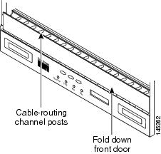
Step 7![]() Using the Cisco TransportPlanner Internal Connections Report, connect one end of the fiber cable plug into the Origination Position.
Using the Cisco TransportPlanner Internal Connections Report, connect one end of the fiber cable plug into the Origination Position.
Step 8![]() Route the fiber cable on the card faceplate through the fiber clip on the faceplate, if provided. (Fiber clips are factory-attached to the faceplates of 32MUX-O, 32DMX, 32DMX-O, OSCM, OSC-CSM, OPT-PRE, OPT-BST, OPT-BST-E, OPT-BST-L, OPT-AMP-L, OPT-AMP-17-C, and OPT-AMP-C cards.)
Route the fiber cable on the card faceplate through the fiber clip on the faceplate, if provided. (Fiber clips are factory-attached to the faceplates of 32MUX-O, 32DMX, 32DMX-O, OSCM, OSC-CSM, OPT-PRE, OPT-BST, OPT-BST-E, OPT-BST-L, OPT-AMP-L, OPT-AMP-17-C, and OPT-AMP-C cards.)
Step 9![]() Route the fiber cable through the cable-routing channel and cutout on the appropriate side of the shelf assembly, as necessary.
Route the fiber cable through the cable-routing channel and cutout on the appropriate side of the shelf assembly, as necessary.
Step 10![]() As needed, route slack fiber-optic cable around the round cable retainers in the fiber-storage tray (Figure 3-11).
As needed, route slack fiber-optic cable around the round cable retainers in the fiber-storage tray (Figure 3-11).
Figure 3-11 Fiber-Storage Tray
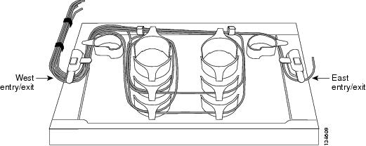
Step 11![]() Route the fiber cable out either side of the fiber-storage tray as necessary.
Route the fiber cable out either side of the fiber-storage tray as necessary.
Step 12![]() Plug the other end of the cable into the Destination position.
Plug the other end of the cable into the Destination position.
Note![]() Cards display an SF LED after the OSC terminations are created (see the G38 Provision OSC Terminations) if transmit and receive fibers are not connected correctly. For example, an RX port is connected to another RX port or a TX port is connected to another TX port.
Cards display an SF LED after the OSC terminations are created (see the G38 Provision OSC Terminations) if transmit and receive fibers are not connected correctly. For example, an RX port is connected to another RX port or a TX port is connected to another TX port.
Step 13![]() Repeat Steps 4 through 12 until you have connected the intra-shelf fibers according to the Cisco TransportPlanner Internal Connections report.
Repeat Steps 4 through 12 until you have connected the intra-shelf fibers according to the Cisco TransportPlanner Internal Connections report.
Step 14![]() To close the fiber-storage tray, push the tray back toward the rack until it locks into place.
To close the fiber-storage tray, push the tray back toward the rack until it locks into place.
Stop. You have completed this procedure.
DLP-G349 Use the Cisco TransportPlanner Internal Connections Report
This task describes how to use the Cisco TransportPlanner Internal Connections report to install cables on the DWDM cards. |
|
Step 1![]() Display the Cisco TransportPlanner Internal Connections report for the node that you are provisioning. The Internal Connections report is presented in two views, a patchcord installation view and a software provisioning view. The Patchcord installation view lists all the patchcord connections that the installer has to mechanically cable within the site between the different ports of the DWDM cards. Figure 3-12 shows an example patchcord installation view. The SW Provisioning view contains all the connections to be manually set or removed via CTC with respect to the default connections that are automatically generated by the system software running on the node. Figure 3-13 shows an example of a software provisioning view.
Display the Cisco TransportPlanner Internal Connections report for the node that you are provisioning. The Internal Connections report is presented in two views, a patchcord installation view and a software provisioning view. The Patchcord installation view lists all the patchcord connections that the installer has to mechanically cable within the site between the different ports of the DWDM cards. Figure 3-12 shows an example patchcord installation view. The SW Provisioning view contains all the connections to be manually set or removed via CTC with respect to the default connections that are automatically generated by the system software running on the node. Figure 3-13 shows an example of a software provisioning view.
The tables identify the patchcords that you must cable by their endpoints. Starting from the left side of report, Position identifies the fiber origination point. The location shown in the next Position to right is the destination point for the fiber connection. The patchcord endpoints are identified by site, assembly shelf, slot, and port number. Information provided by the Internal Connections Software report includes:
- Name—Displays the name of the site. On the SW provisioning view, this column indicates whether the connection was automatically set, or should be manually set or removed via CTC.
- Position—The cable origination in the format is Rack.Shelf.Slot. For example, Rack#1.Shelf Assembly 1.Slot 2 refers to Slot 2 in shelf assembly 1(DWDM) shelf of Rack 1. Refer to the Cisco TransportPlanner Site Dialog box for rack and shelf names and locations.
- Unit—The ONS 15454 DWDM card (unit) that is installed in the Position’s slot. This is where the patchcord originates.
- Port Number—The port number where the patchcord connection originates.
- Port ID—(Software provisioning view only) The port identifier shown in TL1 for the Position-1 connection.
- Port Label—The name of the physical port printed on the DWDM card’s front panel and shown in CTC card view.
- Attenuator—If attenuation is required, the product ID (PID) of the bulk fixed attenuator is shown. “Att-Lpbk-4dB” indicates that the DC TX and DC RX ports on an OPT-PRE (or OPT-AMP-L, OPT-AMP-17-C, or OPT-AMP-C card provisioned in OPT-PRE card mode) card are to be connected with an attenuated loopback that is shipped with the OPT-PRE card. This parameter also indicates when an internal attenuator must be placed between the OPT-PRE DC-TX and DC-RX ports on the when a DCU is equipped.
Note![]() If the Attenuator field is blank, no attenuation is needed.
If the Attenuator field is blank, no attenuation is needed.
- Position—The cable termination in the format is Rack.Shelf.Slot.
- Unit—The ONS 15454 DWDM card that is installed in the Position’s slot. This is where the cabling terminates.
- Port—The port number where the patchcord connection terminates.
- Port ID—(Software provisioning view only) The port identifier shown in TL1 for the Position-2 connection.
- Port Label—The name of the physical port printed on the DWDM card’s front panel and shown in CTC card view.
- P/F—Indicates whether you must create the connection manually in CTC. A Yes appearing in this column means that you must create the connection manually.
Figure 3-12 Cisco TransportPlanner Internal Connections Report—Patchcord Installation View
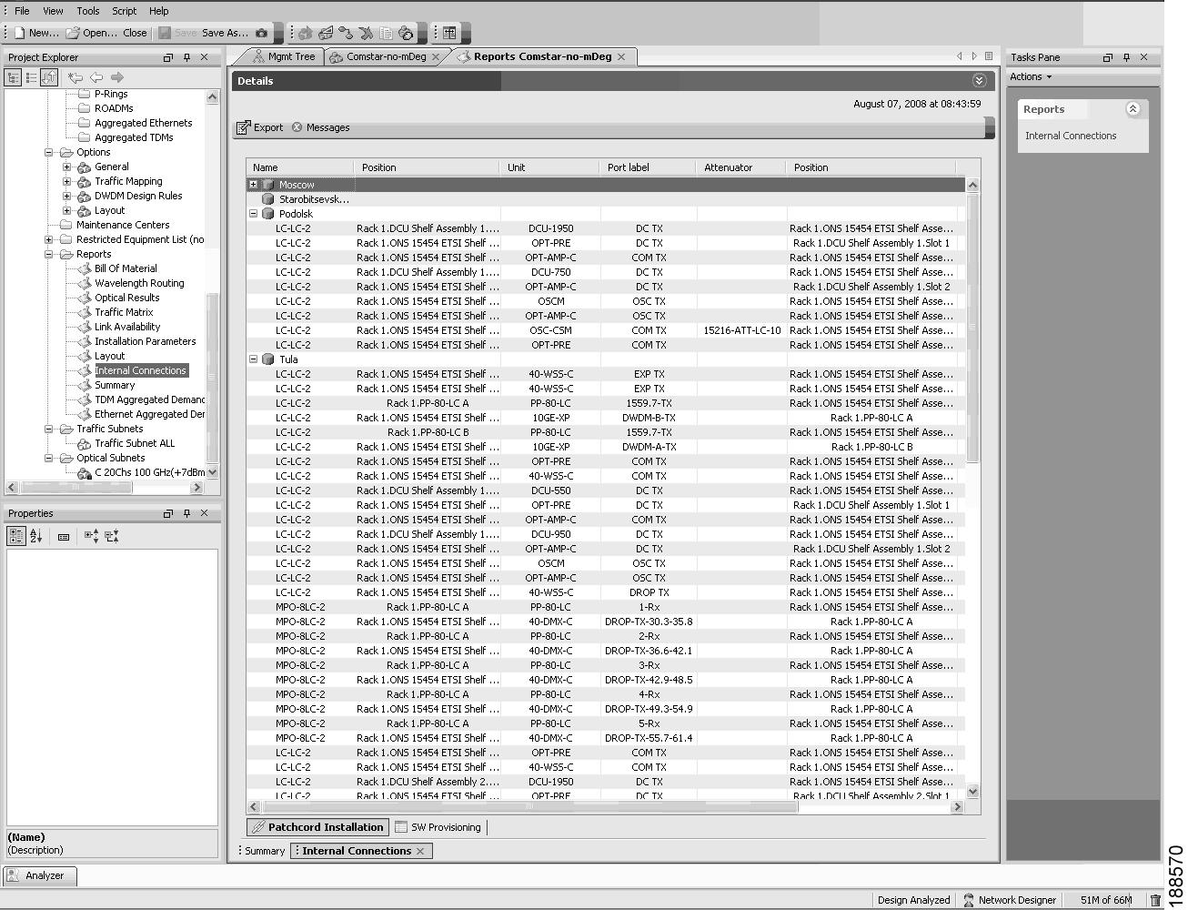
Figure 3-13 Cisco TransportPlanner Internal Connections Report—Software Provisioning View
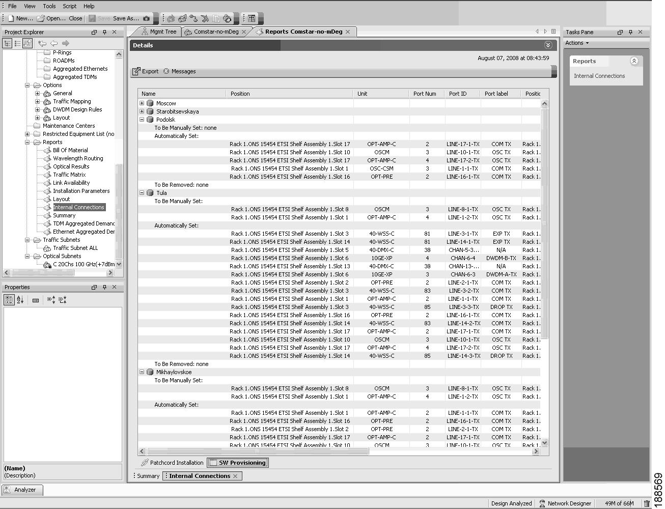
Step 2![]() Return to your originating procedure (NTP).
Return to your originating procedure (NTP).
NTP-G140 Install Fiber-Optic Cables Between Terminal, Hub, or ROADM Nodes
This procedure routes fiber-optic cables from the DWDM optical cards in a terminal, hub, or ROADM node to the patch panel, and from the patch panel to TXP, MXP, GE_XP, 10GE_XP, GE_XPE, 10GE_XPE, or ADM-10G cards. |
|
See Step 1 for a list of equipment specific to each node type. All node types require fiber-optic cables, terminated with a single LC-type connector on each end. |
|
G28 Install the Fiber Patch-Panel Tray G29 Install the Fiber-Storage Tray |
|
Step 1![]() Determine which type of node you are fibering.
Determine which type of node you are fibering.
The following node types require the listed equipment. The cards and patch panels should already be installed before you begin this procedure.
- Terminal node: One 32DMX-O card, one 32MUX-O card, and one standard patch-panel tray or one deep patch-panel tray
- Hub node: Two 32DMX-O cards, two 32MUX-O cards, and two standard patch-panel trays or two deep patch-panel trays
- ROADM node: Two 32WSS cards, two 32DMX cards, and two standard patch-panel trays or two deep patch-panel trays
- Expanded ROADM node: Two 40-WSS-C/40-WSS-CE cards, two 40-DMX-C/40-DMX-CE cards, and two 40-channel patch-panel trays, preinstalled with MPO-LC cables
Note![]() If you are using standard patch panels, you will also need eight multifiber push-on (MPO) cables per standard patch panel. MPO cables are fiber-optic cables terminated on one end with one MPO connector and on the other end with eight LC-type connectors. Deep patch-panel trays come pre-installed with MPO cables.
If you are using standard patch panels, you will also need eight multifiber push-on (MPO) cables per standard patch panel. MPO cables are fiber-optic cables terminated on one end with one MPO connector and on the other end with eight LC-type connectors. Deep patch-panel trays come pre-installed with MPO cables.
Step 2![]() On the front of the patch-panel tray, push the tabs on the left and right sides inward to release the lock on the tray.
On the front of the patch-panel tray, push the tabs on the left and right sides inward to release the lock on the tray.
Step 3![]() Pull the patch-panel tray away from the shelf until it is fully opened.
Pull the patch-panel tray away from the shelf until it is fully opened.
Note![]() The red latch inside the patch-panel tray at the top left corner will automatically click and lock the tray in the open position when you have fully opened the tray.
The red latch inside the patch-panel tray at the top left corner will automatically click and lock the tray in the open position when you have fully opened the tray.
Step 4![]() Depending on the type of patch-panel tray you are using:
Depending on the type of patch-panel tray you are using:
–![]() Complete the G315 Install Fiber-Optic Cables From the 32WSS/32DMX and 32MUX-O/32DMX-O Cards to the Standard Patch-Panel Tray.
Complete the G315 Install Fiber-Optic Cables From the 32WSS/32DMX and 32MUX-O/32DMX-O Cards to the Standard Patch-Panel Tray.
–![]() Complete the G316 Install Fiber-Optic Cables from TXP, MXP, GE_XP, 10GE_XP, GE_XPE, 10GE_XPE, ADM-10G, or OTU2_XP Cards to the Standard Patch-Panel Tray.
Complete the G316 Install Fiber-Optic Cables from TXP, MXP, GE_XP, 10GE_XP, GE_XPE, 10GE_XPE, ADM-10G, or OTU2_XP Cards to the Standard Patch-Panel Tray.
–![]() Complete the G356 Install Fiber-Optic Cables from the 32WSS/32DMX and 32MUX-O/32DMX-O Cards to the Deep Patch-Panel Tray.
Complete the G356 Install Fiber-Optic Cables from the 32WSS/32DMX and 32MUX-O/32DMX-O Cards to the Deep Patch-Panel Tray.
–![]() Complete the G357 Install Fiber-Optic Cables from the TXP, MXP, GE_XP, 10GE_XP, GE_XPE, 10GE_XPE, ADM-10G, or OTU2_XP Cards to the Deep Patch-Panel Tray or 40-Channel Patch-Panel Tray.
Complete the G357 Install Fiber-Optic Cables from the TXP, MXP, GE_XP, 10GE_XP, GE_XPE, 10GE_XPE, ADM-10G, or OTU2_XP Cards to the Deep Patch-Panel Tray or 40-Channel Patch-Panel Tray.
–![]() As needed, complete the G427 Reroute Fiber-Optic Cables in the 40-Channel Patch-Panel Tray to route the MPO cables out of the right side of the tray so they can be easily connected to cards installed on the right side of the shelf (Slots 12 through 17).
As needed, complete the G427 Reroute Fiber-Optic Cables in the 40-Channel Patch-Panel Tray to route the MPO cables out of the right side of the tray so they can be easily connected to cards installed on the right side of the shelf (Slots 12 through 17).
–![]() Complete the G428 Install Fiber-Optic Cables from the 40-WSS-C/40-WSS-CE and 40-DMX-C/40-DMX-CE Cards in an Expanded ROADM, Terminal, or Hub Node to the 40-Channel Patch-Panel Tray
Complete the G428 Install Fiber-Optic Cables from the 40-WSS-C/40-WSS-CE and 40-DMX-C/40-DMX-CE Cards in an Expanded ROADM, Terminal, or Hub Node to the 40-Channel Patch-Panel Tray
Step 5![]() To close the patch-panel tray, unlock it by pressing the red latch in the top left corner, and then push the tray back toward the rack until it locks into place.
To close the patch-panel tray, unlock it by pressing the red latch in the top left corner, and then push the tray back toward the rack until it locks into place.
Stop. You have completed this procedure.
DLP-G315 Install Fiber-Optic Cables From the 32WSS/32DMX and 32MUX-O/32DMX-O Cards to the Standard Patch-Panel Tray
Note![]() For a ROADM or hub node, two patch panels will be used, one for Side B side and one for Side A. The Side B 32WSS/32DMX card will connect to the Side B patch panel. The Side A 32WSS/32DMX card will connect to the Side A patch panel.
For a ROADM or hub node, two patch panels will be used, one for Side B side and one for Side A. The Side B 32WSS/32DMX card will connect to the Side B patch panel. The Side A 32WSS/32DMX card will connect to the Side A patch panel.
Step 1![]() Choose either the Side B or Side A to cable the 32MUX-O and 32DMX-O cards (or the 32WSS and 32DMX cards for a ROADM node).
Choose either the Side B or Side A to cable the 32MUX-O and 32DMX-O cards (or the 32WSS and 32DMX cards for a ROADM node).
Step 2![]() On the patch panel, pull up firmly on the two latches and use them to slide the patch panel up until it snaps in place above the tray (Figure 3-14).
On the patch panel, pull up firmly on the two latches and use them to slide the patch panel up until it snaps in place above the tray (Figure 3-14).
Figure 3-14 Using the Patch-Panel Latches to Slide the Patch Panel Away from the Tray
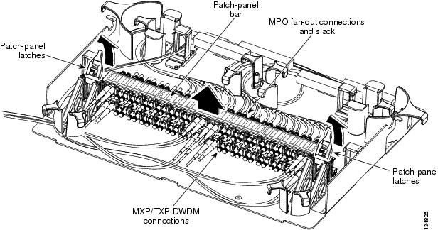
Step 3![]() At the 32WSS or 32MUX-O card in the node, plug the MPO connector of an MPO cable (Figure 3-15) into the top Add RX (30.3–36.6) port of the card. If you are connecting a subsequent MPO cable, plug the MPO connector into the first vacant Add RX card port below the last MPO cable that was installed.
At the 32WSS or 32MUX-O card in the node, plug the MPO connector of an MPO cable (Figure 3-15) into the top Add RX (30.3–36.6) port of the card. If you are connecting a subsequent MPO cable, plug the MPO connector into the first vacant Add RX card port below the last MPO cable that was installed.
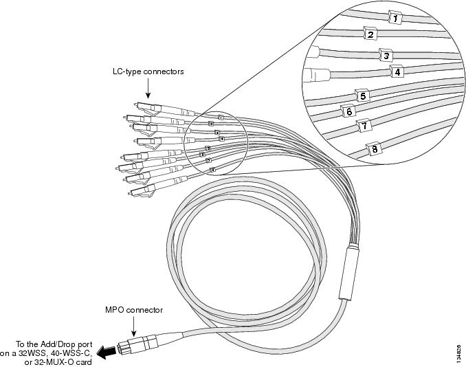
Step 4![]() Route the MPO cable slack through the patch-panel tray as necessary.
Route the MPO cable slack through the patch-panel tray as necessary.
Step 5![]() While facing the front of the patch panel, at the rear side of the patch panel, plug the eight LC-connector fan-out cables on the MPO cable into their corresponding connectors on the bottom row of the patch panel. You should plug the fan-out cables from left to right (as you face the patch panel), following the numbers tagged (1 through 8) on the cables.
While facing the front of the patch panel, at the rear side of the patch panel, plug the eight LC-connector fan-out cables on the MPO cable into their corresponding connectors on the bottom row of the patch panel. You should plug the fan-out cables from left to right (as you face the patch panel), following the numbers tagged (1 through 8) on the cables.
Figure 3-16 shows the patch-panel connectors from the rear of the patch-panel tray. Figure 3-17 shows the assigned wavelengths for each port on the patch panel, as indicated at the top of the patch-panel bar. The numbers on the patch-panel bar correspond to a wavelength on the ITU grid.
Figure 3-16 Rear View of the Patch Panel
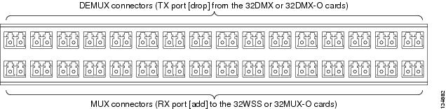
Figure 3-17 Top View of the Patch-Panel Bar

Step 6![]() As necessary, repeat Steps 3 through 5 for the remaining three Add RX ports on the 32WSS or 32MUX-O card, until all 32 LC connectors on the bottom row of the rear of the patch panel are connected.
As necessary, repeat Steps 3 through 5 for the remaining three Add RX ports on the 32WSS or 32MUX-O card, until all 32 LC connectors on the bottom row of the rear of the patch panel are connected.
Step 7![]() At the adjacent 32DMX or 32DMX-O card in the same side of the shelf, plug the MPO connector of an MPO cable into the top Drop TX (30.3–36.6) port of the 32DMX or 32DMX-O card. If you are connecting a subsequent MPO cable, plug the MPO connector into the first vacant Drop TX card port below the last MPO cable that was installed.
At the adjacent 32DMX or 32DMX-O card in the same side of the shelf, plug the MPO connector of an MPO cable into the top Drop TX (30.3–36.6) port of the 32DMX or 32DMX-O card. If you are connecting a subsequent MPO cable, plug the MPO connector into the first vacant Drop TX card port below the last MPO cable that was installed.
Step 8![]() Route the MPO cable slack through the patch-panel tray as necessary.
Route the MPO cable slack through the patch-panel tray as necessary.
Step 9![]() While facing the front of the patch panel, at the rear of the patch panel, plug the eight LC-connector fan-out cables on the MPO cable into their corresponding connectors on the top row of the patch panel. You should plug the fan-out cables from left to right (as you face the patch panel), following the numbers tagged (1 through 8) on the cables.
While facing the front of the patch panel, at the rear of the patch panel, plug the eight LC-connector fan-out cables on the MPO cable into their corresponding connectors on the top row of the patch panel. You should plug the fan-out cables from left to right (as you face the patch panel), following the numbers tagged (1 through 8) on the cables.
Step 10![]() As necessary, repeat Steps 7 through 9 for the remaining three Drop TX ports on the 32DMX or DMX-O card, until all 32 LC connectors on the top row of the rear of the patch panel are connected.
As necessary, repeat Steps 7 through 9 for the remaining three Drop TX ports on the 32DMX or DMX-O card, until all 32 LC connectors on the top row of the rear of the patch panel are connected.
Step 11![]() For a hub or ROADM node, repeat Steps 2 through 10 to cable the other side of the shelf to the second patch panel. For a terminal node, go to Step 12 .
For a hub or ROADM node, repeat Steps 2 through 10 to cable the other side of the shelf to the second patch panel. For a terminal node, go to Step 12 .
Step 12![]() Return to your originating procedure (NTP).
Return to your originating procedure (NTP).
DLP-G316 Install Fiber-Optic Cables from TXP, MXP, GE_XP, 10GE_XP, GE_XPE, 10GE_XPE, ADM-10G, or OTU2_XP Cards to the Standard Patch-Panel Tray
Step 1![]() At the appropriate TXP, MXP, GE_XP, 10GE_XP, GE_XPE, 10GE_XPE, ADM-10G, or OTU2_XP card, plug one end of a fiber-optic cable into the TX port of the DWDM adapter.
At the appropriate TXP, MXP, GE_XP, 10GE_XP, GE_XPE, 10GE_XPE, ADM-10G, or OTU2_XP card, plug one end of a fiber-optic cable into the TX port of the DWDM adapter.
Step 2![]() As needed, route slack fiber-optic cable around the round cable retainers in the fiber-storage tray.
As needed, route slack fiber-optic cable around the round cable retainers in the fiber-storage tray.
Step 3![]() On the DWDM (front) side of the patch panel, plug the other end of the cable into the connector on the bottom row that corresponds to the wavelength to which the TXP, MXP, GE_XP, 10GE_XP, GE_XPE, 10GE_XPE, ADM-10G, or OTU2_XP port is tuned. (See Figure 3-17 for a view of the wavelengths assigned to the patch-panel connectors).
On the DWDM (front) side of the patch panel, plug the other end of the cable into the connector on the bottom row that corresponds to the wavelength to which the TXP, MXP, GE_XP, 10GE_XP, GE_XPE, 10GE_XPE, ADM-10G, or OTU2_XP port is tuned. (See Figure 3-17 for a view of the wavelengths assigned to the patch-panel connectors).
Figure 3-18 shows the patch-panel connectors from the front of the patch-panel tray.
Figure 3-18 Front View of the Patch Panel
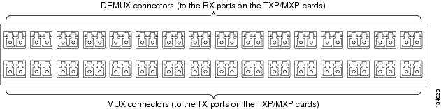
Step 4![]() Plug one end of a fiber-optic cable into the RX port of the DWDM adapter on the TXP, MXP, GE_XP, 10GE_XP, GE_XPE, 10GE_XPE, ADM-10G, or OTU2_XP card.
Plug one end of a fiber-optic cable into the RX port of the DWDM adapter on the TXP, MXP, GE_XP, 10GE_XP, GE_XPE, 10GE_XPE, ADM-10G, or OTU2_XP card.
Step 5![]() On the DWDM (front) side of the patch panel, plug the other end of the cable into the connector on the top row that corresponds to the wavelength to which the TXP, MXP, GE_XP, 10GE_XP, GE_XPE, 10GE_XPE, ADM-10G, or OTU2_XP card is tuned.
On the DWDM (front) side of the patch panel, plug the other end of the cable into the connector on the top row that corresponds to the wavelength to which the TXP, MXP, GE_XP, 10GE_XP, GE_XPE, 10GE_XPE, ADM-10G, or OTU2_XP card is tuned.
Step 6![]() Repeat Steps 1 through 5 for all of the TXP, MXP, GE_XP, 10GE_XP, GE_XPE, 10GE_XPE, ADM-10G, or OTU2_XP cards that you want to connect to this patch panel.
Repeat Steps 1 through 5 for all of the TXP, MXP, GE_XP, 10GE_XP, GE_XPE, 10GE_XPE, ADM-10G, or OTU2_XP cards that you want to connect to this patch panel.
Step 7![]() Return to your originating procedure (NTP).
Return to your originating procedure (NTP).
DLP-G356 Install Fiber-Optic Cables from the 32WSS/32DMX and 32MUX-O/32DMX-O Cards to the Deep Patch-Panel Tray
Note![]() For a ROADM or hub node, two patch panels will be used, one for Side A (Slots 1 through 6) and one for Side B (Slots 12 through 17). The Side B 32WSS/32DMX card will connect to the Side B patch panel. The Side A 32WSS/32DMX card will connect to the Side A patch panel. The MPO cables in the patch panel are preinstalled and routed out of the right side of the patch-panel tray.
For a ROADM or hub node, two patch panels will be used, one for Side A (Slots 1 through 6) and one for Side B (Slots 12 through 17). The Side B 32WSS/32DMX card will connect to the Side B patch panel. The Side A 32WSS/32DMX card will connect to the Side A patch panel. The MPO cables in the patch panel are preinstalled and routed out of the right side of the patch-panel tray.
Step 1![]() Choose either Side A or Side B of the shelf to cable the 32MUX-O and 32DMX-O cards (or the 32WSS and 32DMX cards for a ROADM node).
Choose either Side A or Side B of the shelf to cable the 32MUX-O and 32DMX-O cards (or the 32WSS and 32DMX cards for a ROADM node).
Step 2![]() On the patch panel, locate the MPO connectors (Figure 3-15).
On the patch panel, locate the MPO connectors (Figure 3-15).
Step 3![]() Route the preinstalled MPO cables out of the tray to the right or left (Figure 3-19).
Route the preinstalled MPO cables out of the tray to the right or left (Figure 3-19).
Figure 3-19 Deep Patch-Panel Tray
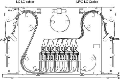
Step 4![]() At the 32WSS or 32MUX-O card in the node, plug the MPO connector labeled 1 RX on an MPO cable (Figure 3-15) into the top Add RX (30.3–36.6) port of the card.
At the 32WSS or 32MUX-O card in the node, plug the MPO connector labeled 1 RX on an MPO cable (Figure 3-15) into the top Add RX (30.3–36.6) port of the card.
Step 5![]() Plug the MPO connector labeled 2-RX into the Add RX (38.1–44.5) port on the card.
Plug the MPO connector labeled 2-RX into the Add RX (38.1–44.5) port on the card.
Step 6![]() Plug the MPO connector labeled 3-RX into the Add RX (46.1–52.5) port on the card.
Plug the MPO connector labeled 3-RX into the Add RX (46.1–52.5) port on the card.
Step 7![]() Plug the MPO connector labeled 4-RX into the Add RX (54.1–60.6) port on the card.
Plug the MPO connector labeled 4-RX into the Add RX (54.1–60.6) port on the card.
Figure 3-20 shows the deep patch-panel ports and corresponding wavelengths.
Figure 3-20 Deep Patch-Panel Port Wavelengths
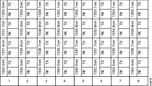
Step 8![]() At the adjacent 32DMX or 32DMX-O card in the same side of the shelf, plug the MPO connector labeled 1 TX on the MPO cable (Figure 3-15) into the top Drop TX (30.3–36.6) port of the card (Figure 3-20).
At the adjacent 32DMX or 32DMX-O card in the same side of the shelf, plug the MPO connector labeled 1 TX on the MPO cable (Figure 3-15) into the top Drop TX (30.3–36.6) port of the card (Figure 3-20).
Step 9![]() Plug the MPO connector labeled 2-TX into the Drop TX (38.1–44.5) port on the card.
Plug the MPO connector labeled 2-TX into the Drop TX (38.1–44.5) port on the card.
Step 10![]() Plug the MPO connector labeled 3-TX into the Drop TX (46.1–52.5) port on the card.
Plug the MPO connector labeled 3-TX into the Drop TX (46.1–52.5) port on the card.
Step 11![]() Plug the MPO connector labeled 4-TX into the Drop TX (54.1–60.6) port on the card.
Plug the MPO connector labeled 4-TX into the Drop TX (54.1–60.6) port on the card.
Step 12![]() For a hub or ROADM node, repeat Steps 2 through 11 to cable the other side of the shelf to the second patch panel. For a terminal node, go to Step 13 .
For a hub or ROADM node, repeat Steps 2 through 11 to cable the other side of the shelf to the second patch panel. For a terminal node, go to Step 13 .
Step 13![]() Return to your originating procedure (NTP).
Return to your originating procedure (NTP).
DLP-G427 Reroute Fiber-Optic Cables in the 40-Channel Patch-Panel Tray
Step 1![]() Carefully unwind all of the MPO cables in the patch-panel tray and gently set the cables to the side of the tray, out of the way of the internal hardware.
Carefully unwind all of the MPO cables in the patch-panel tray and gently set the cables to the side of the tray, out of the way of the internal hardware.
Figure 3-21 and Figure 3-22 show the 40-channel patch-panel tray.
Figure 3-21 40-Channel Patch-Panel Tray, Side View
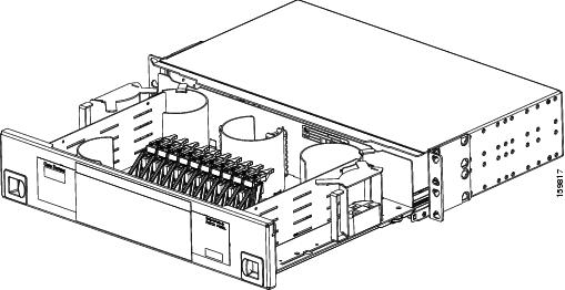
Figure 3-22 40-Channel Patch-Panel Tray, Top View
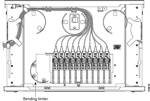
Step 2![]() Slide each of the ten LC-port adapter packs upward.
Slide each of the ten LC-port adapter packs upward.
Step 3![]() Unscrew the two screws in the bottom left bending limiter and remove the bending limiter.
Unscrew the two screws in the bottom left bending limiter and remove the bending limiter.
Step 4![]() Remove the single screw below the center of the patch panel to free the patch panel hardware.
Remove the single screw below the center of the patch panel to free the patch panel hardware.
Step 5![]() Slide the patch panel to the left, and reinstall the screw below the center of the patch panel.
Slide the patch panel to the left, and reinstall the screw below the center of the patch panel.
Step 6![]() Install the bending limiter to the right of the patch panel by installing the two screws.
Install the bending limiter to the right of the patch panel by installing the two screws.
Step 7![]() Carefully route all of the MPO cables around the bending limiter and out the exit on the right side of the patch-panel tray.
Carefully route all of the MPO cables around the bending limiter and out the exit on the right side of the patch-panel tray.
Step 8![]() Slide each of the ten LC-port adapter packs downward.
Slide each of the ten LC-port adapter packs downward.
Step 9![]() Return to your originating procedure (NTP).
Return to your originating procedure (NTP).
DLP-G428 Install Fiber-Optic Cables from the 40-WSS-C/40-WSS-CE and 40-DMX-C/40-DMX-CE Cards in an Expanded ROADM, Terminal, or Hub Node to the 40-Channel Patch-Panel Tray
This task describes how to route fiber-optic cables from 40-WSS-C/40-WSS-CE and 40-DMX-C/40-DMX-CE cards in an expanded ROADM, terminal, or hub node to the 40-channel (80-port) patch-panel tray (15454-PP-80). |
|
The following node types require the following equipment. The cards and patch panels should already be installed before you begin this procedure. Plus one 40-channel patch-panel tray, preinstalled with MPO cables (each MPO cable is terminated on one end with one MPO connector and on the other end with eight LC-type connectors) Plus two 40-channel patch-panel trays, preinstalled with MPO cables (each MPO cable is terminated on one end with one MPO connector and on the other end with eight LC-type connectors) |
|
G34 Install Fiber-Optic Cables on DWDM Cards and DCUs G427 Reroute Fiber-Optic Cables in the 40-Channel Patch-Panel Tray |
|
Note![]() For a ROADM node, two patch panels will be used, one for the Side A (Slots 1 through 6) and one for Side B (Slots 12 through 17). The Side B 40-WSS-C/40-WSS-CE card will connect to the Side B patch panel. The Side A 40-WSS-C/40-WSS-CE will connect to the Side A patch panel. The MPO cables in the patch panel are preinstalled and routed out of the left side of the patch-panel tray.
For a ROADM node, two patch panels will be used, one for the Side A (Slots 1 through 6) and one for Side B (Slots 12 through 17). The Side B 40-WSS-C/40-WSS-CE card will connect to the Side B patch panel. The Side A 40-WSS-C/40-WSS-CE will connect to the Side A patch panel. The MPO cables in the patch panel are preinstalled and routed out of the left side of the patch-panel tray.
Step 1![]() Choose either the Side A or Side B side of the shelf to cable the 40-WSS-C/40-WSS-CE and 40-DMX-C/40-DMX-CE cards.
Choose either the Side A or Side B side of the shelf to cable the 40-WSS-C/40-WSS-CE and 40-DMX-C/40-DMX-CE cards.
Note![]() If you are cabling cards on Side B of the shelf, you must first perform the G427 Reroute Fiber-Optic Cables in the 40-Channel Patch-Panel Tray to route the MPO cables out of the right side of the patch-panel tray, or route the cables through a fiber storage panel.
If you are cabling cards on Side B of the shelf, you must first perform the G427 Reroute Fiber-Optic Cables in the 40-Channel Patch-Panel Tray to route the MPO cables out of the right side of the patch-panel tray, or route the cables through a fiber storage panel.
Step 2![]() On the patch panel, locate the MPO cables and connectors.
On the patch panel, locate the MPO cables and connectors.
Step 3![]() At the 40-WSS-C/40-WSS-CE card in the node, plug the MPO connector labeled 1 RX on an MPO cable (Figure 3-15) into the top Add RX (30.3–35.8) port of the card.
At the 40-WSS-C/40-WSS-CE card in the node, plug the MPO connector labeled 1 RX on an MPO cable (Figure 3-15) into the top Add RX (30.3–35.8) port of the card.
Step 4![]() Plug the MPO connector labeled 2-RX into the Add RX (36.6–42.1) port on the card.
Plug the MPO connector labeled 2-RX into the Add RX (36.6–42.1) port on the card.
Step 5![]() Plug the MPO connector labeled 3-RX into the Add RX (42.9–48.5) port on the card.
Plug the MPO connector labeled 3-RX into the Add RX (42.9–48.5) port on the card.
Step 6![]() Plug the MPO connector labeled 4-RX into the Add RX (49.3–54.9) port on the card.
Plug the MPO connector labeled 4-RX into the Add RX (49.3–54.9) port on the card.
Step 7![]() Plug the MPO connector labeled 5-RX into the Add RX (55.7–61.4) port on the card.
Plug the MPO connector labeled 5-RX into the Add RX (55.7–61.4) port on the card.
Figure 3-23 shows the 40-channel patch-panel ports and corresponding wavelengths.
Figure 3-23 40-Channel (15454-PP-80) Patch-Panel Port Wavelengths
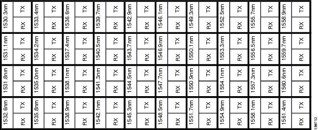
Step 8![]() At the adjacent 40-DMX-C/40-DMX-CE card in the same side of the shelf, plug the MPO connector labeled 1 TX on the MPO cable into the top Drop TX (30.3–35.8) port of the card.
At the adjacent 40-DMX-C/40-DMX-CE card in the same side of the shelf, plug the MPO connector labeled 1 TX on the MPO cable into the top Drop TX (30.3–35.8) port of the card.
Step 9![]() Plug the MPO connector labeled 2-TX into the Drop TX (36.6–42.1) port on the card.
Plug the MPO connector labeled 2-TX into the Drop TX (36.6–42.1) port on the card.
Step 10![]() Plug the MPO connector labeled 3-TX into the Drop TX (42.9–48.5) port on the card.
Plug the MPO connector labeled 3-TX into the Drop TX (42.9–48.5) port on the card.
Step 11![]() Plug the MPO connector labeled 4-TX into the Drop TX (49.3–54.9) port on the card.
Plug the MPO connector labeled 4-TX into the Drop TX (49.3–54.9) port on the card.
Step 12![]() Plug the MPO connector labeled 5-TX into the Drop TX (55.7–61.4) port on the card.
Plug the MPO connector labeled 5-TX into the Drop TX (55.7–61.4) port on the card.
Step 13![]() Repeat Steps 2 through 12 to cable the other side of the shelf to the second patch panel.
Repeat Steps 2 through 12 to cable the other side of the shelf to the second patch panel.
Step 14![]() Return to your originating procedure (NTP).
Return to your originating procedure (NTP).
DLP-G357 Install Fiber-Optic Cables from the TXP, MXP, GE_XP, 10GE_XP, GE_XPE, 10GE_XPE, ADM-10G, or OTU2_XP Cards to the Deep Patch-Panel Tray or 40-Channel Patch-Panel Tray
Step 1![]() Refer to the Cisco TransportPlanner Internal Connections Report to connect the TXP, MXP, GE_XP, 10GE_XP, GE_XPE, 10GE_XPE, ADM-10G, or OTU2_XP card to the proper (Side A or Side B) patch panel. Cisco TransportPlanner designates Side A as Slots 1 to 6 and Side B as Slots 12 to 17. At the appropriate TXP, MXP, GE_XP, 10GE_XP, GE_XPE, 10GE_XPE, ADM-10G, or OTU2_XP card, plug one end of a fiber-optic cable into the TX port of the DWDM adapter.
Refer to the Cisco TransportPlanner Internal Connections Report to connect the TXP, MXP, GE_XP, 10GE_XP, GE_XPE, 10GE_XPE, ADM-10G, or OTU2_XP card to the proper (Side A or Side B) patch panel. Cisco TransportPlanner designates Side A as Slots 1 to 6 and Side B as Slots 12 to 17. At the appropriate TXP, MXP, GE_XP, 10GE_XP, GE_XPE, 10GE_XPE, ADM-10G, or OTU2_XP card, plug one end of a fiber-optic cable into the TX port of the DWDM adapter.
Step 2![]() As needed, route slack fiber-optic cable around the round cable retainers in the fiber-storage tray.
As needed, route slack fiber-optic cable around the round cable retainers in the fiber-storage tray.
Step 3![]() Plug the other end of the cable into the RX connector on the patch panel that corresponds to the wavelength to which the TXP, MXP, GE_XP, 10GE_XP, GE_XPE, 10GE_XPE, ADM-10G, or OTU2_XP port is tuned. (See Figure 3-20 for a view of the wavelengths assigned to the deep patch-panel connectors or Figure 3-23 for a view of the wavelengths assigned to the 40-channel patch-panel connectors).
Plug the other end of the cable into the RX connector on the patch panel that corresponds to the wavelength to which the TXP, MXP, GE_XP, 10GE_XP, GE_XPE, 10GE_XPE, ADM-10G, or OTU2_XP port is tuned. (See Figure 3-20 for a view of the wavelengths assigned to the deep patch-panel connectors or Figure 3-23 for a view of the wavelengths assigned to the 40-channel patch-panel connectors).
Step 4![]() On the patch-panel tray, slide each of the ten LC-port adapter packs upward.
On the patch-panel tray, slide each of the ten LC-port adapter packs upward.
Step 5![]() Plug one end of a fiber-optic cable into the RX port of the DWDM adapter on the TXP, MXP, GE_XP, 10GE_XP, GE_XPE, 10GE_XPE, ADM-10G, or OTU2_XP card.
Plug one end of a fiber-optic cable into the RX port of the DWDM adapter on the TXP, MXP, GE_XP, 10GE_XP, GE_XPE, 10GE_XPE, ADM-10G, or OTU2_XP card.
Step 6![]() Plug the other end of the cable into the TX connector on the patch panel that corresponds to the wavelength to which the TXP, MXP, GE_XP, 10GE_XP, GE_XPE, 10GE_XPE, ADM-10G, or OTU2_XP port is tuned.
Plug the other end of the cable into the TX connector on the patch panel that corresponds to the wavelength to which the TXP, MXP, GE_XP, 10GE_XP, GE_XPE, 10GE_XPE, ADM-10G, or OTU2_XP port is tuned.
Step 7![]() Repeat Steps 1 through 6 for each TXP, MXP, GE_XP, 10GE_XP, GE_XPE, 10GE_XPE, ADM-10G, or OTU2_XP card that you want to connect to this patch panel.
Repeat Steps 1 through 6 for each TXP, MXP, GE_XP, 10GE_XP, GE_XPE, 10GE_XPE, ADM-10G, or OTU2_XP card that you want to connect to this patch panel.
Step 8![]() Return to your originating procedure (NTP).
Return to your originating procedure (NTP).
NTP-G185 Install Fiber-Optic Cables between Mesh Nodes
This procedure describes how to install fiber-optic cables to create mesh nodes. You must route fiber-optic cables from 40-MUX-C and 40-DMX-C cards in a mesh node to the 40-channel (80-port) patch-panel tray (15454-PP-80), and from the 40-WXC-C cards in a mesh node to one of the mesh patch-panel trays (four-degree or eight-degree). |
|
Mesh nodes require the following equipment. The cards and patch panels should already be installed before you begin this procedure. One 40-MUX-C card per side of the mesh node (up to 8 sides per node) One 40-DMX-C card per side of the mesh node (up to 8 sides per node) One 40-channel patch-panel tray per side of the mesh node (up to 8 sides per node) One 40-WXC-C card per side (up to 8 sides per node) One MPO-MPO fiber-optic cable per side (up to 8 sides per node) One LC-LC fiber-optic cable per side (up to 8 sides per node) One four-degree (PP-MESH-4) or eight-degree (PP-MESH-8) mesh patch-panel tray, depending on the type of mesh node you want to install |
|
G34 Install Fiber-Optic Cables on DWDM Cards and DCUs G427 Reroute Fiber-Optic Cables in the 40-Channel Patch-Panel Tray |
|
Step 1![]() Open the patch-panel tray:
Open the patch-panel tray:
- 40-channel patch-panel tray: On the front of the patch-panel tray, push the tabs on the left and right sides inward to release the lock on the tray. Pull the patch-panel tray away from the shelf until it is fully opened.
- Mesh patch-panel tray: On the front of the patch-panel tray, push the tabs on the left and right sides inward to open the front door. Raise the plunger located to the right of the TEST ACCESS Tx port and pull the tray toward away from the rack.
Step 2![]() Complete the G430 Install Fiber-Optic Cables from the 40-MUX-C and 40-DMX-C Cards in a Mesh Node to the 40-Channel Patch-Panel Tray.
Complete the G430 Install Fiber-Optic Cables from the 40-MUX-C and 40-DMX-C Cards in a Mesh Node to the 40-Channel Patch-Panel Tray.
Step 3![]() Complete the G431 Install Fiber-Optic Cables from the 40-WXC-C Cards in a Mesh Node to a Mesh Patch-Panel Tray.
Complete the G431 Install Fiber-Optic Cables from the 40-WXC-C Cards in a Mesh Node to a Mesh Patch-Panel Tray.
Step 4![]() Close the patch-panel tray:
Close the patch-panel tray:
- 40-channel patch-panel tray: Push the tray back toward the rack until it locks into place.
- Mesh patch-panel tray: Raise the plunger located on the right of the TEST ACCESS Tx port and push the tray until the plunger locks into the closed position.
Stop. You have completed this procedure.
DLP-G430 Install Fiber-Optic Cables from the 40-MUX-C and 40-DMX-C Cards in a Mesh Node to the 40-Channel Patch-Panel Tray
This task describes how to route fiber-optic cables from 40-MUX-C and 40-DMX-C cards in mesh node to the 40-channel (80-port) patch-panel tray (15454-PP-80). In a mesh node, one 40-channel patch panel tray is required for each direction. The Side A 40-MUX-C and 40-DMX-C cards will connect to the Side A 40-channel patch panel. The Side B 40-MUX-C and 40-DMX-C cards will connect to the Side B 40-channel patch panel, and so forth, up to a maximum of an eight-degree mesh node (Sides A through H). |
|
The cards and patch panels should already be installed before you begin this procedure. One 40-MUX-C card per side of the mesh node One 40-DMX-C card per side of the mesh node One 40-channel patch-panel trays per side of the mesh node, preinstalled with MPO cables (each MPO cable is terminated on one end with one MPO connector and on the other end with eight LC-type connectors) |
|
G34 Install Fiber-Optic Cables on DWDM Cards and DCUs G427 Reroute Fiber-Optic Cables in the 40-Channel Patch-Panel Tray |
|
Step 1![]() Choose Side A of the shelf to cable the 40-MUX-C and 40-DMX-C cards.
Choose Side A of the shelf to cable the 40-MUX-C and 40-DMX-C cards.
Note![]() If you are cabling any cards from the right side of the shelf (Slots 12 through 17), you must first perform the G427 Reroute Fiber-Optic Cables in the 40-Channel Patch-Panel Tray to route the MPO cables out of the right side of the patch-panel tray, or route the cables through a fiber storage panel.
If you are cabling any cards from the right side of the shelf (Slots 12 through 17), you must first perform the G427 Reroute Fiber-Optic Cables in the 40-Channel Patch-Panel Tray to route the MPO cables out of the right side of the patch-panel tray, or route the cables through a fiber storage panel.
Step 2![]() On the patch panel, locate the MPO cables and connectors.
On the patch panel, locate the MPO cables and connectors.
Step 3![]() At the 40-MUX-C card in the node, plug the MPO connector labeled 1 RX on an MPO cable into the top Add RX (30.3–35.8) port of the card.
At the 40-MUX-C card in the node, plug the MPO connector labeled 1 RX on an MPO cable into the top Add RX (30.3–35.8) port of the card.
Step 4![]() Plug the MPO connector labeled 2-RX into the Add RX (36.6–42.1) port on the card.
Plug the MPO connector labeled 2-RX into the Add RX (36.6–42.1) port on the card.
Step 5![]() Plug the MPO connector labeled 3-RX into the Add RX (42.9–48.5) port on the card.
Plug the MPO connector labeled 3-RX into the Add RX (42.9–48.5) port on the card.
Step 6![]() Plug the MPO connector labeled 4-RX into the Add RX (49.3–54.9) port on the card.
Plug the MPO connector labeled 4-RX into the Add RX (49.3–54.9) port on the card.
Step 7![]() Plug the MPO connector labeled 5-RX into the Add RX (55.7–61.4) port on the card.
Plug the MPO connector labeled 5-RX into the Add RX (55.7–61.4) port on the card.
Step 8![]() At the adjacent 40-DMX-C card in the same side of the shelf, plug the MPO connector labeled 1 TX on the MPO cable.
At the adjacent 40-DMX-C card in the same side of the shelf, plug the MPO connector labeled 1 TX on the MPO cable.
Step 9![]() Plug the MPO connector labeled 2-TX into the Drop TX (36.6–42.1) port on the card.
Plug the MPO connector labeled 2-TX into the Drop TX (36.6–42.1) port on the card.
Step 10![]() Plug the MPO connector labeled 3-TX into the Drop TX (42.9–48.5) port on the card.
Plug the MPO connector labeled 3-TX into the Drop TX (42.9–48.5) port on the card.
Step 11![]() Plug the MPO connector labeled 4-TX into the Drop TX (49.3–54.9) port on the card.
Plug the MPO connector labeled 4-TX into the Drop TX (49.3–54.9) port on the card.
Step 12![]() Plug the MPO connector labeled 5-TX into the Drop TX (55.7–61.4) port on the card.
Plug the MPO connector labeled 5-TX into the Drop TX (55.7–61.4) port on the card.
Step 13![]() Repeat Steps 2 through 12 for the remaining sides of the mesh node (Sides B through H, depending on the type of mesh node you want to cable).
Repeat Steps 2 through 12 for the remaining sides of the mesh node (Sides B through H, depending on the type of mesh node you want to cable).
Step 14![]() Return to your originating procedure (NTP).
Return to your originating procedure (NTP).
DLP-G431 Install Fiber-Optic Cables from the 40-WXC-C Cards in a Mesh Node to a Mesh Patch-Panel Tray
This task connects fiber-optic cables from the 40-WXC-C cards in a mesh node to the 4-degree or 8-degree mesh patch panel. The four-degree patch panel allows up to 4 sides to be used per node, while the eight-degree patch panel allows up to 8 sides to be used per node. |
|
The cards and patch panel trays should already be installed before you begin this procedure. One 40-WXC-C card per side (up to 8 sides per node) One MPO-MPO fiber-optic cable per side One LC-LC fiber-optic cable per side |
|
G28 Install the Fiber Patch-Panel Tray G29 Install the Fiber-Storage Tray |
|
Step 1![]() Choose Side A of the shelf to cable the 40-WXC-C card to the mesh patch panel.
Choose Side A of the shelf to cable the 40-WXC-C card to the mesh patch panel.
Step 2![]() On the mesh patch panel, locate the EXP TX A port and insert one end of an MPO-MPO cable.
On the mesh patch panel, locate the EXP TX A port and insert one end of an MPO-MPO cable.
Step 3![]() Route the MPO cable through the mesh patch panel and out to the 40-WXC-C card on Side A of the node.
Route the MPO cable through the mesh patch panel and out to the 40-WXC-C card on Side A of the node.
Step 4![]() Connect the other end of the MPO cable to the EXP RX port on the 40-WXC-C.
Connect the other end of the MPO cable to the EXP RX port on the 40-WXC-C.
Step 5![]() On the mesh patch panel, locate the COM RX A port and insert one end of an LC-LC cable.
On the mesh patch panel, locate the COM RX A port and insert one end of an LC-LC cable.
Step 6![]() Route the LC cable through the mesh patch panel to the 40-WXC-C card on Side A of the node.
Route the LC cable through the mesh patch panel to the 40-WXC-C card on Side A of the node.
Step 7![]() Connect the other end of the LC cable to the EXP TX port on the 40-WXC-C.
Connect the other end of the LC cable to the EXP TX port on the 40-WXC-C.
Step 8![]() Repeat Steps 1 through 7 as necessary to cable Sides B through D for a 4-degree patch panel, and Sides B through H for an 8-degree patch panel.
Repeat Steps 1 through 7 as necessary to cable Sides B through D for a 4-degree patch panel, and Sides B through H for an 8-degree patch panel.
Stop. You have completed this procedure.
NTP-G191 Install Fiber-Optic Cables on Passthrough ROADM Nodes
Step 1![]() Choose either the East or West side of the first shelf to cable the 32WSS card for the first ROADM node.
Choose either the East or West side of the first shelf to cable the 32WSS card for the first ROADM node.
Step 2![]() Choose the corresponding West or East side of the second shelf to cable the 32WSS card for the second ROADM node.
Choose the corresponding West or East side of the second shelf to cable the 32WSS card for the second ROADM node.
Step 3![]() On the front of the fiber-storage tray that will be used for routing the fiber-optic cable, push the tabs on the left and right sides inward to release the lock on the tray.
On the front of the fiber-storage tray that will be used for routing the fiber-optic cable, push the tabs on the left and right sides inward to release the lock on the tray.
Step 4![]() Pull the fiber-storage tray away from the shelf until it is fully opened.
Pull the fiber-storage tray away from the shelf until it is fully opened.
Step 5![]() Open the fold-down door located at the bottom of both shelf assemblies to expose the cable-routing channels for each (Figure 3-24).
Open the fold-down door located at the bottom of both shelf assemblies to expose the cable-routing channels for each (Figure 3-24).
Figure 3-24 Managing Cables on the Front Panel
Step 6![]() Plug one end of the first 3-meter fiber-optic cable into the EXP-TX connector on the first 32WSS card.
Plug one end of the first 3-meter fiber-optic cable into the EXP-TX connector on the first 32WSS card.
Step 7![]() Route the fiber-optic cable through the shelf cable-routing channel and cutout on the appropriate side of the shelf assembly, as necessary.
Route the fiber-optic cable through the shelf cable-routing channel and cutout on the appropriate side of the shelf assembly, as necessary.
Step 8![]() Route the fiber-optic cable through the vertical fiber guide as needed to reach the entry to the fiber-storage tray.
Route the fiber-optic cable through the vertical fiber guide as needed to reach the entry to the fiber-storage tray.
Step 9![]() Thread the cable into the fiber-storage tray at the appropriate side and around the first bend radius delimiter as shown (Figure 3-25).
Thread the cable into the fiber-storage tray at the appropriate side and around the first bend radius delimiter as shown (Figure 3-25).
Step 10![]() As needed, route slack fiber-optic cable around the slack management cable retainers in the fiber-storage tray (Figure 3-25).
As needed, route slack fiber-optic cable around the slack management cable retainers in the fiber-storage tray (Figure 3-25).
Figure 3-25 Fiber-Storage Tray
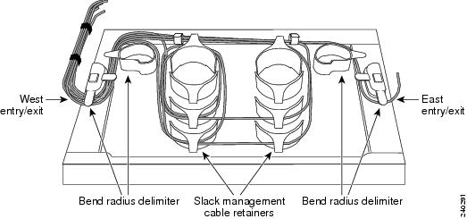
Step 11![]() Thread the fiber cable through the second bend delimiter and out the appropriate side of the fiber-storage tray as necessary.
Thread the fiber cable through the second bend delimiter and out the appropriate side of the fiber-storage tray as necessary.
Step 12![]() Route the fiber-optic cable through the vertical fiber guide as needed to reach the second ROADM shelf where the second 32WSS is located.
Route the fiber-optic cable through the vertical fiber guide as needed to reach the second ROADM shelf where the second 32WSS is located.
Step 13![]() Route the fiber-optic cable through the shelf cutout and through the shelf cable routing channel as needed.
Route the fiber-optic cable through the shelf cutout and through the shelf cable routing channel as needed.
Step 14![]() Plug the end of the 3-meter fiber-optic cable into the EXP-RX port of the second 32WSS card.
Plug the end of the 3-meter fiber-optic cable into the EXP-RX port of the second 32WSS card.
Step 15![]() Plug one end of the second 3-meter fiber-optic cable into the EXP-TX connector on the second 32WSS card.
Plug one end of the second 3-meter fiber-optic cable into the EXP-TX connector on the second 32WSS card.
Step 16![]() Follow Step 7 through Step 14 to connect the EXP-TX connector of the second 32WSS card to the EXP-RX port of the first 32WSS card.
Follow Step 7 through Step 14 to connect the EXP-TX connector of the second 32WSS card to the EXP-RX port of the first 32WSS card.
Step 17![]() Close the fold-down doors located at the bottom of both shelf assemblies and slide the fiber-storage tray back into its normal locked position.
Close the fold-down doors located at the bottom of both shelf assemblies and slide the fiber-storage tray back into its normal locked position.
Stop. You have completed this procedure.
NTP-G141 Install Fiber-Optic Cables for Y-Cable Protection Modules
This procedure installs and routes fiber-optic cables from the client signal to the Y-cable protection module (single mode or multimode), and from the Y-cable module to the transponder node. Using one Y-cable protection module, you can protect one client signal with two TXP, MXP, GE_XP, 10GE_XP, GE_XPE, 10GE_XPE, or OTU2_XP cards, and two client signals with four TXP, MXP, GE_XP, 10GE_XP, GE_XPE, 10GE_XPE, or OTU2_XP cards. You can use Y-cable protection modules that you have installed in a FleyLayer shelf, or Y-cable modules installed in a Y-cable module tray. |
|
G32 Install the Y-Cable Protection Modules in the FlexLayer Shelf G377 Install the Y-Cable Protection Modules in the Y-Cable Module Tray |
|
Note![]() Refer to the “Shelf Assembly Hardware” and “Transponder and Muxponder Cards” chapters in the Cisco ONS 15454 DWDM Reference Manual for more information about Y-cable protection.
Refer to the “Shelf Assembly Hardware” and “Transponder and Muxponder Cards” chapters in the Cisco ONS 15454 DWDM Reference Manual for more information about Y-cable protection.
Note![]() To use Y-cable protection for GE_XP, 10GE_XP, GE_XPE, and 10GE_XPE cards, the cards must be provisioned in 10GE MXP, 20GE MXP, or 10GE TXP mode. (See the G379 Change the GE_XP, 10GE_XP, GE_XPE, and 10GE_XPE Card Mode.) Y-cable protection cannot be used for GE_XP, 10GE_XP, GE_XPE, and 10GE_XPE cards that are provisioned in L2 over DWDM mode.
To use Y-cable protection for GE_XP, 10GE_XP, GE_XPE, and 10GE_XPE cards, the cards must be provisioned in 10GE MXP, 20GE MXP, or 10GE TXP mode. (See the G379 Change the GE_XP, 10GE_XP, GE_XPE, and 10GE_XPE Card Mode.) Y-cable protection cannot be used for GE_XP, 10GE_XP, GE_XPE, and 10GE_XPE cards that are provisioned in L2 over DWDM mode.
Step 1![]() As needed, complete the G375 Install Fiber-Optic Cables on the Y-Cable Modules in the FlexLayer Shelf.
As needed, complete the G375 Install Fiber-Optic Cables on the Y-Cable Modules in the FlexLayer Shelf.
Step 2![]() As needed, complete the G376 Install Fiber-Optic Cables on the Y-Cable Modules in the Y-Cable Module Tray.
As needed, complete the G376 Install Fiber-Optic Cables on the Y-Cable Modules in the Y-Cable Module Tray.
Stop. You have completed this procedure.
DLP-G375 Install Fiber-Optic Cables on the Y-Cable Modules in the FlexLayer Shelf
This task installs fiber-optic cables from the TXP, MXP, GE_XP, 10GE_XP, GE_XPE, or 10GE_XPE cards to the Y-cable modules installed in the FlexLayer shelves, and from the Y-cable modules to the client devices. |
|
G32 Install the Y-Cable Protection Modules in the FlexLayer Shelf G179 Install the TXP, MXP, GE_XP, 10GE_XP, GE_XPE, 10GE_XPE, ADM-10G, and OTU2_XP Cards |
|
Step 1![]() Referring to the Cisco TransportPlanner Internal Connections Report, install a fiber-optic cable between a TXP, MXP, GE_XP, 10GE_XP, GE_XPE, or 10GE_XPE card and a Y-cable module.
Referring to the Cisco TransportPlanner Internal Connections Report, install a fiber-optic cable between a TXP, MXP, GE_XP, 10GE_XP, GE_XPE, or 10GE_XPE card and a Y-cable module.
If you want to protect one client signal, connect the fiber-optic cables according to either Table 3-6 or Table 3-7 . To protect two client signals using a single Y-cable module, connect the cables according to both Table 3-6 and Table 3-7 .
|
|
|
|---|---|
|
|
|
|---|---|
Step 2![]() As needed, route slack fiber-optic cable around the round cable retainers in the fiber-storage tray as you install cables between the Y-cable module and the TXP, MXP, GE_XP, 10GE_XP, GE_XPE, or 10GE_XPE cards (Figure 3-11).
As needed, route slack fiber-optic cable around the round cable retainers in the fiber-storage tray as you install cables between the Y-cable module and the TXP, MXP, GE_XP, 10GE_XP, GE_XPE, or 10GE_XPE cards (Figure 3-11).
Step 3![]() Install a fiber-optic cable between the client device and the Y-cable module where you just installed a fiber-optic cable to the TXP, MXP, GE_XP, 10GE_XP, GE_XPE, or 10GE_XPE card.
Install a fiber-optic cable between the client device and the Y-cable module where you just installed a fiber-optic cable to the TXP, MXP, GE_XP, 10GE_XP, GE_XPE, or 10GE_XPE card.
Step 4![]() Repeat Steps 1 through 3 for each Y-cable module you need to use for Y-cable protection.
Repeat Steps 1 through 3 for each Y-cable module you need to use for Y-cable protection.
Step 5![]() Return to your originating procedure (NTP).
Return to your originating procedure (NTP).
DLP-G376 Install Fiber-Optic Cables on the Y-Cable Modules in the Y-Cable Module Tray
This task installs fiber-optic cables from the TXP, MXP, GE_XP, 10GE_XP, GE_XPE, or 10GE_XPE cards to the Y-cable modules installed in the Y-cable module tray, and from the Y-cable modules to the client devices. |
|
Fiber-optic cables (4-meter [13.12-foot]), single-mode or multimode as appropriate |
|
G32 Install the Y-Cable Protection Modules in the FlexLayer Shelf G179 Install the TXP, MXP, GE_XP, 10GE_XP, GE_XPE, 10GE_XPE, ADM-10G, and OTU2_XP Cards |
|
Step 1![]() Open the drawer of the tray by pushing inward on the latches located at the left and right front of the tray.
Open the drawer of the tray by pushing inward on the latches located at the left and right front of the tray.
Step 2![]() On each Y-cable module you will connect, use the tab to slide the module up so that it is fully extended and easily accessible in the tray.
On each Y-cable module you will connect, use the tab to slide the module up so that it is fully extended and easily accessible in the tray.
Step 3![]() Referring to the Cisco TransportPlanner Internal Connections Report, install a 4-meter (13.12-foot) fiber-optic cable (single-mode or multimode, as appropriate) between a TXP, MXP, GE_XP, 10GE_XP, GE_XPE, or 10GE_XPE card and the Y-cable module installed farthest to the left. Proceed according to the port label affixed to the front of the tray to identify the ports on each installed module (Figure 3-26).
Referring to the Cisco TransportPlanner Internal Connections Report, install a 4-meter (13.12-foot) fiber-optic cable (single-mode or multimode, as appropriate) between a TXP, MXP, GE_XP, 10GE_XP, GE_XPE, or 10GE_XPE card and the Y-cable module installed farthest to the left. Proceed according to the port label affixed to the front of the tray to identify the ports on each installed module (Figure 3-26).
Figure 3-26 Y-Cable Protection Port Label
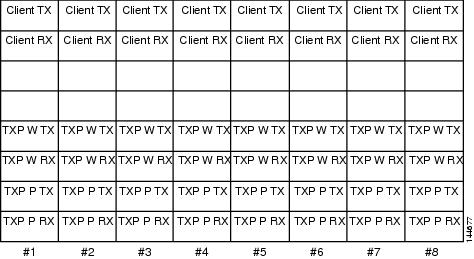
Note![]() You can use the label shown in Figure 3-26 to take notes as to which wavelength/port you are connecting to each Y-cable module. “W” denotes the indicated Working port on the TXP, MXP, GE_XP, 10GE_XP, GE_XPE, or 10GE_XPE card. “P” denotes the indicated Protect port on the TXP, MXP, GE_XP, 10GE_XP, GE_XPE, or 10GE_XPE card.
You can use the label shown in Figure 3-26 to take notes as to which wavelength/port you are connecting to each Y-cable module. “W” denotes the indicated Working port on the TXP, MXP, GE_XP, 10GE_XP, GE_XPE, or 10GE_XPE card. “P” denotes the indicated Protect port on the TXP, MXP, GE_XP, 10GE_XP, GE_XPE, or 10GE_XPE card.
Note![]() Protective covers are installed over the third and fourth ports on the Y-cable modules because they are not used.
Protective covers are installed over the third and fourth ports on the Y-cable modules because they are not used.
As needed, route slack fiber-optic cable around the round cable retainers in theY-cable module tray as you install cables between the Y-cable module and the TXP, MXP, GE_XP, 10GE_XP, GE_XPE, or 10GE_XPE card (Figure 3-27).
Figure 3-27 Y-Cable Protection Module Tray
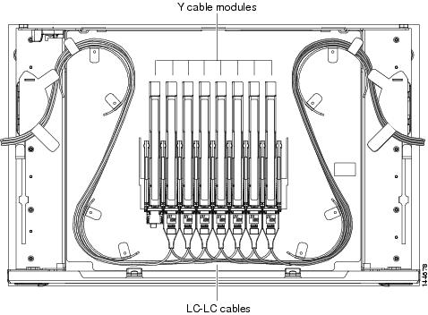
Step 4![]() Referring to the Cisco TransportPlanner Internal Connections Report, install a fiber-optic cable of adequate length (single-mode or multimode, as appropriate) between the Y-cable module and the client signal that you want to protect.
Referring to the Cisco TransportPlanner Internal Connections Report, install a fiber-optic cable of adequate length (single-mode or multimode, as appropriate) between the Y-cable module and the client signal that you want to protect.
Step 5![]() As needed, route slack fiber-optic cable around the round cable retainers in theY-cable module tray as you install cables between the Y-cable module and the TXP, MXP, GE_XP, 10GE_XP, GE_XPE, or 10GE_XPE card.
As needed, route slack fiber-optic cable around the round cable retainers in theY-cable module tray as you install cables between the Y-cable module and the TXP, MXP, GE_XP, 10GE_XP, GE_XPE, or 10GE_XPE card.
Step 6![]() Repeat Steps 2 through 5 for each Y-cable module you need to use for Y-cable protection.
Repeat Steps 2 through 5 for each Y-cable module you need to use for Y-cable protection.
Step 7![]() To close the tray, unlock the drawer from the open position by depressing the red lock at the back left of the tray and push the tray closed.
To close the tray, unlock the drawer from the open position by depressing the red lock at the back left of the tray and push the tray closed.
Step 8![]() Return to your originating procedure (NTP).
Return to your originating procedure (NTP).
NTP-G152 Create and Verify Internal Patchcords
This procedure creates the default internal patchcords, verifies the installed cards, and calculates the connections that should be provisioned for them. |
|
Step 1![]() Complete the G46 Log into CTC at the node where you want to provision the DWDM cable connections. If you are already logged in, continue with Step 2.
Complete the G46 Log into CTC at the node where you want to provision the DWDM cable connections. If you are already logged in, continue with Step 2.
Step 2![]() In node view (single-shelf mode) or multishelf view (multishelf mode), click the Provisioning > WDM-ANS > Internal Patchcords tabs.
In node view (single-shelf mode) or multishelf view (multishelf mode), click the Provisioning > WDM-ANS > Internal Patchcords tabs.
Step 3![]() Click Default Patchcords.
Click Default Patchcords.
CTC verifies that the cards installed in the ONS 15454 shelf are compatible and will operate together as a valid DWDM node configuration. Furthermore, based on the cards installed or preprovisioned, CTC calculates the intra-shelf patchcords that are expected to be installed.
Note![]() The Internal Patchcords tab does not show OPT-PRE DCU connections or span connections.
The Internal Patchcords tab does not show OPT-PRE DCU connections or span connections.
Note![]() The connections calculation is not based on the Cisco TransportPlanner shelf layout or Internal Connections report. Calculations are based on the cards that are physically installed. If the Cisco TransportPlanner shelf layout calls for a hub node but OADM cards are installed, CTC calculates connections based on the cards expected for an OADM node.
The connections calculation is not based on the Cisco TransportPlanner shelf layout or Internal Connections report. Calculations are based on the cards that are physically installed. If the Cisco TransportPlanner shelf layout calls for a hub node but OADM cards are installed, CTC calculates connections based on the cards expected for an OADM node.
Note![]() The number of rows in the Maintenance > DWDM > Mesh Patch Panel Internal Patchcords tab are created dynamically, as per the number of sides present in a node.
The number of rows in the Maintenance > DWDM > Mesh Patch Panel Internal Patchcords tab are created dynamically, as per the number of sides present in a node.
Step 4![]() If no errors were generated, continue with Step 5. If errors appear, verify that the cards installed in the shelf match the Cisco TransportPlanner shelf layout. If the wrong cards are installed or are missing, install the correct cards following the G30 Install the DWDM Cards.
If no errors were generated, continue with Step 5. If errors appear, verify that the cards installed in the shelf match the Cisco TransportPlanner shelf layout. If the wrong cards are installed or are missing, install the correct cards following the G30 Install the DWDM Cards.
Step 5![]() Verify that the connections in the Internal Patchcords tab match the connections in the Cisco TransportPlanner Internal Connections Report for the DWDM cards (see the G349 Use the Cisco TransportPlanner Internal Connections Report). The Internal Patchcords tab will not show OPT-PRE DCU connections or span connections.
Verify that the connections in the Internal Patchcords tab match the connections in the Cisco TransportPlanner Internal Connections Report for the DWDM cards (see the G349 Use the Cisco TransportPlanner Internal Connections Report). The Internal Patchcords tab will not show OPT-PRE DCU connections or span connections.
Step 6![]() Complete the G354 Create an Internal Patchcord Manually for any connections that require manual provisioning, for example, to create patchcords between TXP and MXP trunk ports and OCH filter ports. If you need to delete a connection, complete the G355 Delete an Internal Patchcord.
Complete the G354 Create an Internal Patchcord Manually for any connections that require manual provisioning, for example, to create patchcords between TXP and MXP trunk ports and OCH filter ports. If you need to delete a connection, complete the G355 Delete an Internal Patchcord.
Note![]() Although CTC calculates most DWDM connections automatically, some connections cannot be calculated because of the DWDM card type and position. You must create these connections manually. For example, connections related to optical bypass circuits must be manually provisioned.
Although CTC calculates most DWDM connections automatically, some connections cannot be calculated because of the DWDM card type and position. You must create these connections manually. For example, connections related to optical bypass circuits must be manually provisioned.
Stop. You have completed this procedure.
DLP-G354 Create an Internal Patchcord Manually
This task creates an internal patchcord manually when CTC is unable to calculate the internal patchcords automatically. |
|
Note![]() Use only one management interface to complete the creation of internal patchcords. For example, do not begin the internal patchcord creation using the TL1 interface or CTP XML file and end the internal patchcord creation using CTC.
Use only one management interface to complete the creation of internal patchcords. For example, do not begin the internal patchcord creation using the TL1 interface or CTP XML file and end the internal patchcord creation using CTC.
Step 1![]() In node view (single-shelf mode) or multishelf view (multishelf mode), click the Provisioning > WDM-ANS > Internal Patchcord tabs.
In node view (single-shelf mode) or multishelf view (multishelf mode), click the Provisioning > WDM-ANS > Internal Patchcord tabs.
Step 3![]() Choose one of the following link types for the internal patchcord. See Table 3-8 for a list of ports that are available for each option.
Choose one of the following link types for the internal patchcord. See Table 3-8 for a list of ports that are available for each option.
- Trunk to Trunk (L2)—Configures a port for control traffic communication between the trunk ports of GE_XP, 10GE_XP, GE_XPE, or 10GE_XPE cards.
- OCH-Trunk to OCH-FILTER—Creates an internal patchcord between an optical channel trunk port on a TXP/MXP stage card (which includes TXP, MXP, GE_XP, 10GE_XP, GE_XPE, 10GE_XPE, ADM-10G, OTU2_XP, or ITU-T line cards) and an optical channel filter port on an add/drop stage card (which includes 32MUX, 40-MUX-C, 32WSS, 40-WSS-C/40-WSS-CE, 32DMX, 32DMX-O, or 40DMX cards).
You can use this option to also create an internal patchcord between an optical channel trunk port on a TXP/MXP stage card (which includes TXP, MXP, GE_XP, 10GE_XP, GE_XPE, 10GE_XPE, ADM-10G, OTU2_XP, or ITU-T line cards) and the COM port on a PSM card in channel protection configuration (where, PSM card is equipped between one TXP/MXP stage and two add/drop stages). In this case, the Internal Patchcord Creation wizard will guide you to create the patchcords between the working and protect ports on the PSM card and the ports on the two different add/drop stage cards (which includes 32MUX, 40-MUX-C, 32WSS, 40-WSS-C/40-WSS-CE, 32DMX, 32DMX-O, or 40DMX cards).
Note![]() Manual creation of OTS/OCH to OTS/OCH internal patchcords should never be needed for standard DWDM nodes. Manual creation might be needed for non-standard nodes, for example, a hub node that has wavelength selective switches installed. Manual creation will be recommended by Cisco TransportPlanner.
Manual creation of OTS/OCH to OTS/OCH internal patchcords should never be needed for standard DWDM nodes. Manual creation might be needed for non-standard nodes, for example, a hub node that has wavelength selective switches installed. Manual creation will be recommended by Cisco TransportPlanner.
The remaining fields on the page depend on the patchcord type selected.
- OCHNC Wavelength (OCH-Trunk to OCH-FILTER only)—Sets the OCHNC wavelength for the OCH trunk to OCH filter internal patchcord. Use the unnamed band selection box below to display C-band or L band wavelengths in the OCHNC Wavelength field. Provision the OCHNC wavelength to the wavelength provisioned for the TXP, MXP, GE_XP, 10GE_XP, GE_XPE, or 10GE_XPE, ADM-10G, OTU2_XP, or ITU-T line card trunk port.
- Bidirectional (OTS/OCH to OTS/OCH only)—If selected, creates a bidirectional OTS/OCH to OTS/OCH internal patchcord.
Note![]() To successfully create an internal patchcord between WSS/DMX channel port and TXP trunk port, the TXP must be chosen as "From" endpoint while WSS/DMX must be chosen as "To" endpoint.
To successfully create an internal patchcord between WSS/DMX channel port and TXP trunk port, the TXP must be chosen as "From" endpoint while WSS/DMX must be chosen as "To" endpoint.
|
|
|
|
|
|---|---|---|---|
TXP, MXP, GE_XP, 10GE_XP, GE_XPE, 10GE_XPE, ADM-10G, OTU2_XP, or ITU-T line card |
|||
Step 5![]() On the Internal Patchcord Creation page, provision the internal patchcord origination parameters.
On the Internal Patchcord Creation page, provision the internal patchcord origination parameters.
- Side—Select the side where the internal patchcord originates. This field is visible only if you have chosen the OCH-Filter to OCH-Filter option in Step 3.
- PSM Protection—Select this check box if you have provisioned a PSM card in channel protection configuration. This field is visible only if you have chosen the OCH-Filter to OCH-Filter option in Step 3.
Note![]() If you select the PSM Protection check box, the Side field is automatically grayed out.
If you select the PSM Protection check box, the Side field is automatically grayed out.
- Autorun Wizard—Select this check box if you want the Internal Patchcord Creation wizard to execute automatically and create the patchcords without any user intervention. This field is visible only if you have chosen the OCH-Filter to OCH-Filter option in Step 3.
Note![]() The wizard will stop and wait for user input only for the Side field.
The wizard will stop and wait for user input only for the Side field.
- Shelf—(Multishelf nodes only) Choose the shelf where the internal patchcord originates.
- Slot—Choose the slot containing the card where the internal patchcord originates. Refer to Table 3-8 for a list of cards that are available, based on the patchcord type chosen in Step 3.
- Port—Choose the TX port where the internal patchcord originates.
Step 7![]() In the Internal Patchcord Termination page, provision the internal patchcord termination parameters.
In the Internal Patchcord Termination page, provision the internal patchcord termination parameters.
Note![]() If you select the PSM Protection check box, the Side field is automatically grayed out.
If you select the PSM Protection check box, the Side field is automatically grayed out.
Note![]() The wizard will stop and wait for user input only for the Side field.
The wizard will stop and wait for user input only for the Side field.
- Shelf—(Multishelf nodes only) Choose the shelf where the internal patchcord terminates.
- Slot—Choose the slot containing the card where the internal patchcord terminates. Refer to Table 3-8 for a list of cards that are available, based on the patchcord type chosen in Step 3.
- Port—Choose the RX port where the internal patchcord terminates.
Step 8![]() Click Next. If you chose the OTS/OCH to OTS/OCH patchcord type Step 3
Click Next. If you chose the OTS/OCH to OTS/OCH patchcord type Step 3![]() and did not choose bidirectional, continue with Step 12. Otherwise, continue with the next step.
and did not choose bidirectional, continue with Step 12. Otherwise, continue with the next step.
Step 9![]() Review the display-only information on the Internal Patchcord Origination Reverse page. This page shows the shelf (multishelf nodes only), slot, and port that CTC will use for the opposite internal patchcord origination route.
Review the display-only information on the Internal Patchcord Origination Reverse page. This page shows the shelf (multishelf nodes only), slot, and port that CTC will use for the opposite internal patchcord origination route.
Step 11![]() Review the information displayed on the Internal Patchcord Termination Reverse page. This display-only page shows the shelf (multishelf nodes only), slot, and port that CTC will use for the reverse internal patchcord termination route.
Review the information displayed on the Internal Patchcord Termination Reverse page. This display-only page shows the shelf (multishelf nodes only), slot, and port that CTC will use for the reverse internal patchcord termination route.
Step 12![]() Click Finish. The new internal patchcord appears on the Internal Patchcord table.
Click Finish. The new internal patchcord appears on the Internal Patchcord table.
Step 13![]() Return to your originating procedure (NTP).
Return to your originating procedure (NTP).
DLP-G355 Delete an Internal Patchcord
Step 1![]() In node view (single-shelf mode) or multishelf view (multishelf mode), click the Provisioning > WDM-ANS > Internal Patchcord tabs.
In node view (single-shelf mode) or multishelf view (multishelf mode), click the Provisioning > WDM-ANS > Internal Patchcord tabs.
Step 2![]() Click the connection you want to delete.
Click the connection you want to delete.
Step 3![]() Click Delete, then click Yes.
Click Delete, then click Yes.
Step 4![]() Return to your originating procedure (NTP).
Return to your originating procedure (NTP).
NTP-G209 Create, Edit, and Delete Optical Sides
This procedure allows you to create, edit, and delete optical sides on a DWDM node. |
|
G143 Import the Cisco TransportPlanner NE Update Configuration File |
|
Note![]() For any node type including mesh nodes, the association between the shelf, linecard and side is reported in the left top window of CTC (Vital Status Pane) in the mode view.
For any node type including mesh nodes, the association between the shelf, linecard and side is reported in the left top window of CTC (Vital Status Pane) in the mode view.
Note![]() For mesh nodes, the association between sides and the 40-WXC-C cards can be found in the Maintenance > DWDM > Mesh Patch Panel Internal Patchcords screen.
For mesh nodes, the association between sides and the 40-WXC-C cards can be found in the Maintenance > DWDM > Mesh Patch Panel Internal Patchcords screen.
For example:
PP-MESH, LC (A): Shelf 1, Slot 3 (40 WXC), port EXP-TX
PP-MESH, MPO (A): Shelf 1, Slot 3 (40 WXC), port EXP-RX
The above rows indicate that the:
WXC port located in Shelf 1, Slot 3 is connected to the LC connector A (Side A) on PP-MESH.
WXC port located in Shelf 1, Slot 3 is connected to the MPO connector A (Side A) on PP-MESH.
Step 1![]() Complete the G46 Log into CTC at the node where you want to provision the optical side. If you are already logged in, continue with Step 2.
Complete the G46 Log into CTC at the node where you want to provision the optical side. If you are already logged in, continue with Step 2.
Step 2![]() As needed, complete the following tasks:
As needed, complete the following tasks:
- Complete the G491 Create an Optical Side.
- Complete the G492 Edit an Optical Side.
- Complete the G480 Delete an Optical Side.
Stop. You have completed this procedure.
DLP-G491 Create an Optical Side
This task creates an optical side. For more details on optical sides, refer to the “Node Reference” chapter in the Cisco ONS 15454 DWDM Reference Manual. |
|
Step 1![]() In node view (single-shelf mode) or multishelf view (multishelf mode), click the Provisioning > WDM-ANS > Optical Sides tabs.
In node view (single-shelf mode) or multishelf view (multishelf mode), click the Provisioning > WDM-ANS > Optical Sides tabs.
Step 3![]() In the Create Side dialog box, enter the following:
In the Create Side dialog box, enter the following:
- Side ID—Choose a side ID (A, B,C, D, E, F, G, or H) from the drop-down list.
- Line In—Choose an RX port from the drop-down list.
- Line Out—Choose a TX port from the drop-down list.
Note![]() For a terminal node equipped with a PSM card in line or muliplex section protection configuration, you can only choose the W-RX and W-TX ports while creating an optical side. After you create the working (w) optical side, the TCC2/TCC2P card automatically creates the protected (p) optical side involving the P-RX and P-TX ports of the PSM card. CTC refreshes the Optical Sides tab with both the working and protected optical sides.
For a terminal node equipped with a PSM card in line or muliplex section protection configuration, you can only choose the W-RX and W-TX ports while creating an optical side. After you create the working (w) optical side, the TCC2/TCC2P card automatically creates the protected (p) optical side involving the P-RX and P-TX ports of the PSM card. CTC refreshes the Optical Sides tab with both the working and protected optical sides.
Step 4![]() Return to your originating procedure (NTP).
Return to your originating procedure (NTP).
Step 1![]() In node view (single-shelf mode) or multishelf view (multishelf mode), click the Provisioning > WDM-ANS > Optical Sides tabs.
In node view (single-shelf mode) or multishelf view (multishelf mode), click the Provisioning > WDM-ANS > Optical Sides tabs.
Step 2![]() Click the optical side that you want to edit.
Click the optical side that you want to edit.
Step 4![]() In the Edit Side ID dialog box, choose a side ID (A, B,C, D, E, F, G, or H) from the drop-down list.
In the Edit Side ID dialog box, choose a side ID (A, B,C, D, E, F, G, or H) from the drop-down list.
Step 6![]() Return to your originating procedure (NTP).
Return to your originating procedure (NTP).
DLP-G480 Delete an Optical Side
Step 1![]() In node view (single-shelf mode) or multishelf view (multishelf mode), click Provisioning > WDM-ANS > Optical Sides tabs.
In node view (single-shelf mode) or multishelf view (multishelf mode), click Provisioning > WDM-ANS > Optical Sides tabs.
Step 2![]() Click the optical side that you want to delete.
Click the optical side that you want to delete.
Step 4![]() In the confirmation dialog box, click Yes to continue.
In the confirmation dialog box, click Yes to continue.
Step 5![]() Return to your originating procedure (NTP).
Return to your originating procedure (NTP).
NTP-G38 Provision OSC Terminations
This procedure provisions the OSC terminations. The OSC provides a bidirectional channel that connects all nodes within a DWDM ring. The OSC carries a supervisory data channel and synchronizes clocking at network nodes. The OSC also carries a user data channel. |
|
G143 Import the Cisco TransportPlanner NE Update Configuration File |
|
Note![]() This procedure automatically turns on any OPT-RAMP-C cards installed in the DWDM ring.
This procedure automatically turns on any OPT-RAMP-C cards installed in the DWDM ring.
Note![]() The DCCs, GCCs, and OSCs should not be provisioned between SONET (ANSI) and SDH (ETSI) nodes using CTC or TL1 because they cannot operate between SONET and SDH nodes. These communication channels should be provisioned on similar nodes, such as SONET-to-SONET or SDH-to-SDH.
The DCCs, GCCs, and OSCs should not be provisioned between SONET (ANSI) and SDH (ETSI) nodes using CTC or TL1 because they cannot operate between SONET and SDH nodes. These communication channels should be provisioned on similar nodes, such as SONET-to-SONET or SDH-to-SDH.
Step 1![]() Complete the G46 Log into CTC at the node where you want to provision the OSC terminations. If you are already logged in, continue with Step 2.
Complete the G46 Log into CTC at the node where you want to provision the OSC terminations. If you are already logged in, continue with Step 2.
Step 2![]() In node view (single-shelf mode) or multishelf view (multishelf mode), click the Provisioning > Comm Channels > OSC tabs.
In node view (single-shelf mode) or multishelf view (multishelf mode), click the Provisioning > Comm Channels > OSC tabs.
Step 3![]() In the OSC Terminations area, click Create (Figure 3-28).
In the OSC Terminations area, click Create (Figure 3-28).
Figure 3-28 OSC Terminations Area
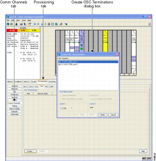
Step 4![]() In the Create OSC Terminations dialog box, choose the ports where you want to create the OSC termination. To select more than one port, press the Shift key (to select a range of ports) or the Ctrl key (to select multiple individual ports).
In the Create OSC Terminations dialog box, choose the ports where you want to create the OSC termination. To select more than one port, press the Shift key (to select a range of ports) or the Ctrl key (to select multiple individual ports).
Note![]() The number of OSC terminations that you create depends on the node type defined by Cisco TransportPlanner. Terminal nodes require one OSC termination. Hub, OADM, and ROADM nodes require two OSC terminations.
The number of OSC terminations that you create depends on the node type defined by Cisco TransportPlanner. Terminal nodes require one OSC termination. Hub, OADM, and ROADM nodes require two OSC terminations.
Step 5![]() In the Layer 3 area, check the OSI box if the following conditions are met:
In the Layer 3 area, check the OSI box if the following conditions are met:
If you checked OSI, complete the following steps. If not, continue with Step 6.
b.![]() Provision the following fields:
Provision the following fields:
- Router—Choose the OSI router.
- ESH—Set the ESH propagation frequency. End system NEs transmit ESHs to inform other ESs and ISs about the NSAPs they serve. The default is 10 seconds. The range is 10 to 1000 seconds.
- ISH—Sets the ISH PDU propagation frequency. Intermediate system NEs send ISHs to other ESs and ISs to inform them about the IS NETs it serves. The default is 10 seconds. The range is 10 to 1000 seconds.
- IIH—Sets the IIH PDU propagation frequency. The IS-IS Hello PDUs establish and maintain adjacencies between ISs. The default is 3 seconds. The range is 1 to 600 seconds.
- Metric—Sets the cost for sending packets on the LAN subnet. The IS-IS protocol uses the cost to calculate the shortest routing path. The default metric cost for LAN subnets is 20. It normally should not be changed.
Step 6![]() Click Finish. Ports are automatically placed in service. The following alarms might appear in the node view (single-shelf mode) or multishelf view (multishelf mode) Alarms tab Description field. They will remain until all the network OSC connections between the adjacent nodes are created:
Click Finish. Ports are automatically placed in service. The following alarms might appear in the node view (single-shelf mode) or multishelf view (multishelf mode) Alarms tab Description field. They will remain until all the network OSC connections between the adjacent nodes are created:
Note![]() After the OSC termination is created, the line ports are placed in service and span power levels are checked.
After the OSC termination is created, the line ports are placed in service and span power levels are checked.
Stop. You have completed this procedure.
NTP-G37 Run Automatic Node Setup
This procedure runs the Launch ANS function. Launch ANS applies the ANS parameters (calculated in the G143 Import the Cisco TransportPlanner NE Update Configuration File or the G169 Calculate ANS Installation Values for Installation Without Cisco TransportPlanner) to the node and to the ports for cards installed in the node. The applied ANS parameters include span loss values, threshold values, power references, and others. Launch ANS also sets the VOA references based on the calculated power references. |
|
G139 Verify Cisco TransportPlanner Reports and Files G152 Create and Verify Internal Patchcords G143 Import the Cisco TransportPlanner NE Update Configuration File |
|
Note![]() If you are provisioning ANS parameters that were not calculated using Cisco TransportPlanner, do not complete this procedure until after you complete the G169 Calculate ANS Installation Values for Installation Without Cisco TransportPlanner.
If you are provisioning ANS parameters that were not calculated using Cisco TransportPlanner, do not complete this procedure until after you complete the G169 Calculate ANS Installation Values for Installation Without Cisco TransportPlanner.
Note![]() ANS provisioning parameters must be calculated by Cisco Transport Planner. ANS provisioning parameters must be manually changed by Cisco qualified personnel only. Setting wrong ANS provisioning (either as pre-amplifier or booster input power thresholds) may impact traffic.
ANS provisioning parameters must be calculated by Cisco Transport Planner. ANS provisioning parameters must be manually changed by Cisco qualified personnel only. Setting wrong ANS provisioning (either as pre-amplifier or booster input power thresholds) may impact traffic.
Step 1![]() Complete the G46 Log into CTC at the node where you want to run ANS. If you are already logged in, continue with Step 2.
Complete the G46 Log into CTC at the node where you want to run ANS. If you are already logged in, continue with Step 2.
Step 2![]() Referring to the Cisco TransportPlanner Installation Parameters (see Table 3-1), identify the parameters that have a Yes in the Manually Set column. If there are no parameters that have a Yes in the Manually Set column, continue with Step 6.
Referring to the Cisco TransportPlanner Installation Parameters (see Table 3-1), identify the parameters that have a Yes in the Manually Set column. If there are no parameters that have a Yes in the Manually Set column, continue with Step 6.
Step 3![]() In CTC, display the card where the parameter is to be manually provisioned in card view.
In CTC, display the card where the parameter is to be manually provisioned in card view.
Step 4![]() Enter the specified Calibration parameter from the Cisco TransportPlanner Installation Parameters table. Click Apply.
Enter the specified Calibration parameter from the Cisco TransportPlanner Installation Parameters table. Click Apply.
Step 5![]() Repeat Steps 2 through 4 for each parameter in the Cisco TransportPlanner Installation Parameters table that displays Yes in the Manually Set field.
Repeat Steps 2 through 4 for each parameter in the Cisco TransportPlanner Installation Parameters table that displays Yes in the Manually Set field.
Step 6![]() Change to node view (single-shelf mode) or multishelf view (multishelf mode).
Change to node view (single-shelf mode) or multishelf view (multishelf mode).
Step 7![]() Click the Provisioning > WDM-ANS > Port Status tabs.
Click the Provisioning > WDM-ANS > Port Status tabs.
Step 9![]() In the Apply Launch ANS dialog box, click Yes.
In the Apply Launch ANS dialog box, click Yes.
Step 10![]() In the Launch ANS confirmation dialog box, click OK.
In the Launch ANS confirmation dialog box, click OK.
Step 11![]() Verify that one of the following statuses appears in the Link Status column for all ports:
Verify that one of the following statuses appears in the Link Status column for all ports:
If one of the following statuses is shown, complete the provided instructions:
- Fail - Out of Range—The calculated setpoint is outside the expected range. If this status appears, do not continue until you have investigated and cleared the cause. This status might appear because of an error in the Cisco TransportPlanner file. It could also appear because the insertion loss of the installed cards is greater than the estimated insertion loss calculated by Cisco TransportPlanner. If so, the Cisco TransportPlanner file will need to be recalculated. If the installation without Cisco TransportPlanner function is being used, an error could have occurred in the retrieval of values from the far-end nodes. The error could be caused by an incorrect CTC calculation, or by an incorrect manual calculation. All of these possible causes should be investigated. Contact your next level of support if you are unable to clear this status.
- Fail - Port in IS State—The parameter could not be calculated because the port is in service. This status should normally not appear at this point in node turn-up. If it does, display the card in card view, change the port administrative state to OOS,DSLB (ANSI) or Locked,disabled (ETSI), and repeat Steps 6 through 11 .
Note![]() If the ports that are in service carry circuits, you must delete the circuits before you can place the ports out of service. See the G347 Delete Optical Channel Client Connections, the G418 Delete an Optical Channel Trail, or the G106 Delete Optical Channel Network Connections.
If the ports that are in service carry circuits, you must delete the circuits before you can place the ports out of service. See the G347 Delete Optical Channel Client Connections, the G418 Delete an Optical Channel Trail, or the G106 Delete Optical Channel Network Connections.
Stop. You have completed this procedure.
NTP-G39 Verify OSCM Transmit Power
This procedure verifies that the transmit power for the ONS 15454 OSCM and the OSC-CSM cards is correct. |
|
Note![]() Throughout this procedure, Side A refers to Slots 1 through 6, and Side B refers to Slots 12 through 17.
Throughout this procedure, Side A refers to Slots 1 through 6, and Side B refers to Slots 12 through 17.
Step 1![]() Complete the G46 Log into CTC at the node where you want to verify the OSCM or OSC-CSM transmit power. If you are already logged in, continue with Step 2.
Complete the G46 Log into CTC at the node where you want to verify the OSCM or OSC-CSM transmit power. If you are already logged in, continue with Step 2.
Step 2![]() Disable automatic laser shutdown (ALS) on Side A or (for terminal nodes) the terminal side OSCM or OSC-CSM card:
Disable automatic laser shutdown (ALS) on Side A or (for terminal nodes) the terminal side OSCM or OSC-CSM card:
a.![]() In the node view (single-shelf mode) or shelf view (multishelf mode), double-click the Side A or terminal-side OSCM or OSC-CSM card.
In the node view (single-shelf mode) or shelf view (multishelf mode), double-click the Side A or terminal-side OSCM or OSC-CSM card.
b.![]() Click the Maintenance > ALS tabs.
Click the Maintenance > ALS tabs.
c.![]() From the ALS Mode drop-down list, choose Disable.
From the ALS Mode drop-down list, choose Disable.
d.![]() Click Apply. Click Yes in the confirmation dialog box.
Click Apply. Click Yes in the confirmation dialog box.
Step 3![]() If an OSC-CSM or OSCM card is installed on Side B, complete the following steps. If not, continue with Step 4.
If an OSC-CSM or OSCM card is installed on Side B, complete the following steps. If not, continue with Step 4.
a.![]() In the node view (single-shelf mode) or shelf view (multishelf mode), double-click the Side B OSCM or OSC-CSM card.
In the node view (single-shelf mode) or shelf view (multishelf mode), double-click the Side B OSCM or OSC-CSM card.
b.![]() Click the Maintenance > ALS tabs.
Click the Maintenance > ALS tabs.
c.![]() From the ALS Mode drop-down list, choose Disable.
From the ALS Mode drop-down list, choose Disable.
d.![]() Click Apply. Click Yes in the confirmation dialog box.
Click Apply. Click Yes in the confirmation dialog box.
Step 4![]() Complete the G314 Verify OSCM Transmit Power.
Complete the G314 Verify OSCM Transmit Power.
Step 5![]() Change ALS to Auto Restart on the Side A or (for terminal nodes) the terminal side OSCM or OSC-CSM card:
Change ALS to Auto Restart on the Side A or (for terminal nodes) the terminal side OSCM or OSC-CSM card:
a.![]() In the node view (single-shelf mode) or shelf view (multishelf mode), double-click the Side A or terminal-side OSCM or OSC-CSM card.
In the node view (single-shelf mode) or shelf view (multishelf mode), double-click the Side A or terminal-side OSCM or OSC-CSM card.
b.![]() Click the Maintenance > ALS tabs.
Click the Maintenance > ALS tabs.
c.![]() From the ALS Mode drop-down list, choose Auto Restart.
From the ALS Mode drop-down list, choose Auto Restart.
d.![]() Click Apply. Click Yes in the confirmation dialog box.
Click Apply. Click Yes in the confirmation dialog box.
Step 6![]() If an OSC-CSM or OSCM card is installed on Side B, complete the following steps. If not, you have completed this procedure.
If an OSC-CSM or OSCM card is installed on Side B, complete the following steps. If not, you have completed this procedure.
a.![]() In the node view (single-shelf mode) or shelf view (multishelf mode), double-click Side B OSCM or OSC-CSM card.
In the node view (single-shelf mode) or shelf view (multishelf mode), double-click Side B OSCM or OSC-CSM card.
b.![]() Click the Maintenance > ALS tabs.
Click the Maintenance > ALS tabs.
c.![]() From the ALS Mode drop-down list, choose Auto Restart.
From the ALS Mode drop-down list, choose Auto Restart.
d.![]() Click Apply. Click Yes in the confirmation dialog box.
Click Apply. Click Yes in the confirmation dialog box.
Stop. You have completed this procedure.
DLP-G314 Verify OSCM Transmit Power
This task verifies that the transmit power of the OSCM card is correct. |
|
Step 1![]() Display the OSCM card in card view.
Display the OSCM card in card view.
Step 2![]() Click the Provisioning > Optical Line > Parameters tabs.
Click the Provisioning > Optical Line > Parameters tabs.
Step 3![]() Record the Port 3 (OSC TX) Power value: _____.
Record the Port 3 (OSC TX) Power value: _____.
Step 4![]() Change to node view (single-shelf mode) or multishelf view (multishelf mode), then click the Provisioning > WDM-ANS > Provisioning tabs.
Change to node view (single-shelf mode) or multishelf view (multishelf mode), then click the Provisioning > WDM-ANS > Provisioning tabs.
Step 5![]() Record the OSC Power value under the OSCM card in the tree view.
Record the OSC Power value under the OSCM card in the tree view.
Step 6![]() If the power value recorded in Step 3 is not within the range of +/– 0.5 dBm recorded in Step 5, complete the following steps. Otherwise, continue with Step 7.
If the power value recorded in Step 3 is not within the range of +/– 0.5 dBm recorded in Step 5, complete the following steps. Otherwise, continue with Step 7.
a.![]() Click the Maintenance > ALS tabs. Verify that the ALS Command is set to OSRI Off. If not, choose Off from the drop-down list. Click Apply, then click Yes.
Click the Maintenance > ALS tabs. Verify that the ALS Command is set to OSRI Off. If not, choose Off from the drop-down list. Click Apply, then click Yes.
b.![]() Clean the optical connections. See the G115 Clean Fiber Connectors.
Clean the optical connections. See the G115 Clean Fiber Connectors.
c.![]() Complete the following procedures:
Complete the following procedures:
- Delete the two OSC channels using the G186 Delete an OSC Termination.
- Complete the G37 Run Automatic Node Setup.
- Create the OSC channels using the G38 Provision OSC Terminations.
d.![]() Repeat Step 3 through 6 . If the power level is still not within the specified range, contact your next level of support.
Repeat Step 3 through 6 . If the power level is still not within the specified range, contact your next level of support.
Step 7![]() Return to your originating procedure (NTP).
Return to your originating procedure (NTP).
NTP-G163 Upgrade Nodes in Single-Shelf Mode to Multishelf Mode
Step 1![]() Complete the G46 Log into CTC at the node that you want to configure as a multishelf node.
Complete the G46 Log into CTC at the node that you want to configure as a multishelf node.
Step 2![]() If you want to configure a shelf as the node controller, continue with Step 3. If you want to configure a shelf as a subtending shelf, continue with Step 4.
If you want to configure a shelf as the node controller, continue with Step 3. If you want to configure a shelf as a subtending shelf, continue with Step 4.
Step 3![]() To set up the login node as the node controller, complete the following steps:
To set up the login node as the node controller, complete the following steps:
a.![]() In node view (single-node mode) or multishelf view (multishelf mode), click the Provisioning > General > Multishelf Config tabs.
In node view (single-node mode) or multishelf view (multishelf mode), click the Provisioning > General > Multishelf Config tabs.
b.![]() Click Enable as Node Controller.
Click Enable as Node Controller.
c.![]() From the LAN Config drop-down list, complete one of the following:
From the LAN Config drop-down list, complete one of the following:
- Choose Ethernet Switch if MS-ISC-100T cards or the Catalyst 2950 switches are already installed and configured.
- Choose Stand-Alone if MS-ISC-100T cards are not installed yet but will be in the final layout or if this is a line amplifier or an OSC-only site. This option will allow a safe migration of the TCC2/TCC2P database when the multishelf configuration is complete.
e.![]() In the confirmation dialog box, click Yes to allow the node to reboot. The CTC view changes to network view and the node icon changes to gray. Wait for the reboot to finish. (This might take several minutes.)
In the confirmation dialog box, click Yes to allow the node to reboot. The CTC view changes to network view and the node icon changes to gray. Wait for the reboot to finish. (This might take several minutes.)
f.![]() After the node reboots, double-click the node. The multishelf view appears.
After the node reboots, double-click the node. The multishelf view appears.
Note![]() The shelf ID of the node controller is automatically assigned as 1.
The shelf ID of the node controller is automatically assigned as 1.
Step 4![]() To add a node as a subtending shelf in the multishelf configuration, complete the following:
To add a node as a subtending shelf in the multishelf configuration, complete the following:
a.![]() In multishelf view, right-click in the white space in the rack and choose Add Shelf.
In multishelf view, right-click in the white space in the rack and choose Add Shelf.
b.![]() In the Shelf ID Selection dialog box, choose a shelf ID (from 2 to 8) from the drop-down list.
In the Shelf ID Selection dialog box, choose a shelf ID (from 2 to 8) from the drop-down list.
c.![]() Click OK. The shelf appears in the multishelf view.
Click OK. The shelf appears in the multishelf view.
d.![]() Preprovision the new shelf so that it has the same provisioning as the actual shelf that you will add as the subtending shelf:
Preprovision the new shelf so that it has the same provisioning as the actual shelf that you will add as the subtending shelf:
- Cards, PPMs, administrative states, client and trunk port configuration—For more information on card and port settings, see Chapter5, “Provision Transponder and Muxponder Cards”
- Timing—For more information, see the G53 Set Up Timing.
- GCC—For more information, see the G76 Provision DCC/GCC Terminations.
e.![]() Disconnect the cross-over (CAT-5) LAN cable from the RJ-45 (LAN) port of the subtending shelf TCC2/TCC2P card in Slot 11.
Disconnect the cross-over (CAT-5) LAN cable from the RJ-45 (LAN) port of the subtending shelf TCC2/TCC2P card in Slot 11.
f.![]() Connect your Windows PC or Solaris workstation NIC to the RJ-45 (LAN) port on the TTC2/TCC2P card in Slot 11.
Connect your Windows PC or Solaris workstation NIC to the RJ-45 (LAN) port on the TTC2/TCC2P card in Slot 11.
g.![]() Complete the G46 Log into CTC at the subtending shelf.
Complete the G46 Log into CTC at the subtending shelf.
h.![]() Click the Provisioning > General > Multishelf Config tabs.
Click the Provisioning > General > Multishelf Config tabs.
i.![]() Click Enable as Subtended Shelf.
Click Enable as Subtended Shelf.
j.![]() From the Shelf ID drop-down list, choose the shelf ID that you created in Step b .
From the Shelf ID drop-down list, choose the shelf ID that you created in Step b .
l.![]() In the confirmation dialog box, click Yes to reboot the shelf. The CTC view changes to network view and the node icon changes to gray. Wait for the reboot to finish. (This might take several minutes.)
In the confirmation dialog box, click Yes to reboot the shelf. The CTC view changes to network view and the node icon changes to gray. Wait for the reboot to finish. (This might take several minutes.)
m.![]() Disconnect your Windows PC or Solaris workstation network interface card (NIC) from the RJ-45 (LAN) port of the subtending shelf TTC2/TCC2P card in Slot 11.
Disconnect your Windows PC or Solaris workstation network interface card (NIC) from the RJ-45 (LAN) port of the subtending shelf TTC2/TCC2P card in Slot 11.
n.![]() Reconnect the cross-over (CAT-5) LAN cable (disconnected in Step e ) to the RJ-45 (LAN) port of the subtending shelf TCC2/TCC2P card in Slot 11.
Reconnect the cross-over (CAT-5) LAN cable (disconnected in Step e ) to the RJ-45 (LAN) port of the subtending shelf TCC2/TCC2P card in Slot 11.
Note![]() The Ethernet cable must be connected to the subtended shelf TCC2/TCC2P card soon after this TCC2/TCC2P card completes its boot phase (when it becomes active and its peer TCC2/TCC2P card starts rebooting). Connecting it before the TCC2/TCC2P card completes its boot phase is a risk in the conversion process. Connecting it long time after completion of the boot phase might affect traffic due to missing provisioning.
The Ethernet cable must be connected to the subtended shelf TCC2/TCC2P card soon after this TCC2/TCC2P card completes its boot phase (when it becomes active and its peer TCC2/TCC2P card starts rebooting). Connecting it before the TCC2/TCC2P card completes its boot phase is a risk in the conversion process. Connecting it long time after completion of the boot phase might affect traffic due to missing provisioning.
o.![]() Repeat Steps a through n to set up additional subtending shelves.
Repeat Steps a through n to set up additional subtending shelves.
Note![]() Cisco Transport Manager (CTM) users can use the CTM NE Explorer to monitor and configure single-shelf and multishelf nodes. When the upgrade is complete, the original individual subtending shelves will remain the CTM network view and must be manually deleted. For detailed information, refer to the Cisco Transport Manager User Guide, Appendix B, “NE Explorer Information.”
Cisco Transport Manager (CTM) users can use the CTM NE Explorer to monitor and configure single-shelf and multishelf nodes. When the upgrade is complete, the original individual subtending shelves will remain the CTM network view and must be manually deleted. For detailed information, refer to the Cisco Transport Manager User Guide, Appendix B, “NE Explorer Information.”
Stop. You have completed this procedure.
NTP-G210 Provision Node for SNMPv3
Step 1![]() Complete the G46 Log into CTC on the node on which you want to set up SNMPv3. If you are already logged in, go to Step 2.
Complete the G46 Log into CTC on the node on which you want to set up SNMPv3. If you are already logged in, go to Step 2.
Step 2![]() In node view, click the Provisioning > SNMP > SNMP V3 tabs.
In node view, click the Provisioning > SNMP > SNMP V3 tabs.
Step 3![]() Complete the following tasks as required:
Complete the following tasks as required:
Note![]() A group named default_group is defined in the initial configuration. The default group has read and notify access to the complete MIB tree.
A group named default_group is defined in the initial configuration. The default group has read and notify access to the complete MIB tree.
Note![]() A view named full_view is defined in the initial configuration. It includes the complete MIB tree supported on the node.
A view named full_view is defined in the initial configuration. It includes the complete MIB tree supported on the node.
Stop. You have completed this procedure.
NTP-G211 Provision Node to Send SNMPv3 Traps
Step 1![]() Complete the G46 Log into CTC on the node on which you want to set up SNMPv3. If you are already logged in, go to Step 2.
Complete the G46 Log into CTC on the node on which you want to set up SNMPv3. If you are already logged in, go to Step 2.
Step 2![]() In node view, click the Provisioning > SNMP > SNMP V3 tabs.
In node view, click the Provisioning > SNMP > SNMP V3 tabs.
Step 3![]() Complete the following tasks as required:
Complete the following tasks as required:
- G496 Create an SNMPv3 User
- G498 Create Group Access
- G497 Create MIB Views
- G501 Create Notification Filters
- G499 Configure SNMPv3 Trap Destination. When you configure an SNMPv3 trap destination, use the IP address of the NMS, and the port number on which the NMS is listening for traps.
Stop. You have completed this procedure.
NTP-G212 Manually Provision a GNE/ENE to Manage an ENE using SNMPv3
This procedure describes how to manually configure a GNE/ENE to allow the NMS to manage an ENE using SNMPv3. |
|
Step 1![]() Complete the G46 Log into CTC on the node on which you want to set up SNMPv3. If you are already logged in, go to Step 2.
Complete the G46 Log into CTC on the node on which you want to set up SNMPv3. If you are already logged in, go to Step 2.
Step 4![]() Click Provisioning > SNMP > SNMP V3 > General and note the context engine ID. The is required in Step 8
Click Provisioning > SNMP > SNMP V3 > General and note the context engine ID. The is required in Step 8![]() .
.
Step 6![]() Complete the G496 Create an SNMPv3 User to create an SNMPv3 user on the GNE.
Complete the G496 Create an SNMPv3 User to create an SNMPv3 user on the GNE.
Step 7![]() Complete the following tasks as needed on the ENE:
Complete the following tasks as needed on the ENE:
Step 8![]() Complete the G502 Manually Configure the SNMPv3 Proxy Forwarder Table. Use the from Step 4, the local user details created in Step 6, and the remote user created in Step 7.
Complete the G502 Manually Configure the SNMPv3 Proxy Forwarder Table. Use the from Step 4, the local user details created in Step 6, and the remote user created in Step 7.
Stop. You have completed this procedure.
NTP-G213 Automatically Provision a GNE to Manage an ENE using SNMPv3
This procedure describes how to automatically configure a GNE to allow an NMS to manage an ENE using SNMPv3. |
|
Step 1![]() Complete the G46 Log into CTC on the node on which you want to set up SNMPv3. If you are already logged in, go to Step 2.
Complete the G46 Log into CTC on the node on which you want to set up SNMPv3. If you are already logged in, go to Step 2.
Step 4![]() Complete the G496 Create an SNMPv3 User to create an SNMPv3 user on the GNE.
Complete the G496 Create an SNMPv3 User to create an SNMPv3 user on the GNE.
Step 5![]() Complete the G503 Automatically Configure the SNMPv3 Proxy Forwarder Table. Use the GNE user that you defined in Step 4 when you configure the Proxy Forwarder table.
Complete the G503 Automatically Configure the SNMPv3 Proxy Forwarder Table. Use the GNE user that you defined in Step 4 when you configure the Proxy Forwarder table.
Note![]() When you use the automatic procedure, CTC automatically creates an ons_proxy user on the ENE, provides ENE user details for the proxy configuration, and provides the of the ENE.
When you use the automatic procedure, CTC automatically creates an ons_proxy user on the ENE, provides ENE user details for the proxy configuration, and provides the of the ENE.
Stop. You have completed this procedure.
NTP-G214 Manually Provision a GNE/ENE to Send SNMPv3 Traps from an ENE using SNMPv3
This procedure describes how to manually configure the GNE/ENE to allow an ENE to send SNMPv3 traps to the NMS. |
|
Step 1![]() Complete the G46 Log into CTC on the node on which you want to set up SNMPv3. If you are already logged in, go to Step 2.
Complete the G46 Log into CTC on the node on which you want to set up SNMPv3. If you are already logged in, go to Step 2.
Step 4![]() Complete the G496 Create an SNMPv3 User to create an SNMPv3 user on the GNE.
Complete the G496 Create an SNMPv3 User to create an SNMPv3 user on the GNE.
Step 5![]() On the GNE, complete the G499 Configure SNMPv3 Trap Destination. The target IP address must be the IPv4 or IPv6 address of the NMS. For the UDP Port number, use the port number on which the NMS is listening for traps. Use the user name configured in Step 4. Also, specify a target tag name.
On the GNE, complete the G499 Configure SNMPv3 Trap Destination. The target IP address must be the IPv4 or IPv6 address of the NMS. For the UDP Port number, use the port number on which the NMS is listening for traps. Use the user name configured in Step 4. Also, specify a target tag name.
Step 7![]() Complete the G496 Create an SNMPv3 User to create an SNMPv3 user on the ENE.
Complete the G496 Create an SNMPv3 User to create an SNMPv3 user on the ENE.
Step 8![]() Complete the following tasks as required:
Complete the following tasks as required:
- G498 Create Group Access to create a group on the ENE
- G497 Create MIB Views to create a MIB view on the ENE
- G501 Create Notification Filters
Step 9![]() On the ENE, complete the G499 Configure SNMPv3 Trap Destination. The target IP address should be the IP address of the GNE. The UDP port number is 161. Use the user name configured in Step 7.
On the ENE, complete the G499 Configure SNMPv3 Trap Destination. The target IP address should be the IP address of the GNE. The UDP port number is 161. Use the user name configured in Step 7.
Step 10![]() From the network view, click the Provisioning > SNMPv3 tabs.
From the network view, click the Provisioning > SNMPv3 tabs.
Step 11![]() Complete the G504 Manually Configure the SNMPv3 Proxy Trap Forwarder Table.
Complete the G504 Manually Configure the SNMPv3 Proxy Trap Forwarder Table.
The source of the trap must be the IP address of the ENE. For the field, provide the of the ENE. Also, you need to specify the target tag defined in Step 5, and the incoming user details configured in Step 7.
Stop. You have completed this procedure.
NTP-G215 Automatically Provision a GNE/ENE to Send SNMPv3 Traps from an ENE Using SNMPv3
This procedure describes how to automatically configure the GNE/ENE to allow an ENE to send SNMPv3 traps to the NMS. |
|
Step 1![]() Complete the G46 Log into CTC on the node on which you want to set up SNMPv3. If you are already logged in, go to Step 2.
Complete the G46 Log into CTC on the node on which you want to set up SNMPv3. If you are already logged in, go to Step 2.
Step 4![]() Complete the task G496 Create an SNMPv3 User to create an SNMPv3 user on the GNE.
Complete the task G496 Create an SNMPv3 User to create an SNMPv3 user on the GNE.
Step 5![]() On the GNE, complete the following tasks:
On the GNE, complete the following tasks:
- G499 Configure SNMPv3 Trap Destination. The target IP address must be the IPv4 or IPv6 address of the NMS. For the UDP Port number, use the port number on which the NMS is listening for traps. Also, specify a target tag name.
- G505 Automatically Configure the SNMPv3 Proxy Trap Forwarder Table. Use the target tag configured in Step 4. Use the IP address of the ENE as the source of trap. The following details are created automatically:
–![]() A user named ons_trap_user on the ENE
A user named ons_trap_user on the ENE
–![]() Trap destination on the ENE with an IP address of the GNE as the target IP and 161 as the UDP port number
Trap destination on the ENE with an IP address of the GNE as the target IP and 161 as the UDP port number
–![]() Remote user details of the ENE on the GNE
Remote user details of the ENE on the GNE
Stop. You have completed this procedure.
DLP-G496 Create an SNMPv3 User
Step 1![]() In node view, click the Provisioning > SNMP > SNMP V3 > User tabs.
In node view, click the Provisioning > SNMP > SNMP V3 > User tabs.
Step 3![]() In the Create User dialog box, enter the following information:
In the Create User dialog box, enter the following information:
- User Name—Specify the name of the user on the host that connects to the agent. The user name must be a minimum of six and a maximum of 20 alphanumeric (a-z, A-Z, 0-9) characters. For TL1 compatibility, the user name must be of 6 to 10 characters.
- Group Name—Specify the group to which the user belongs.
- Authentication
–![]() Protocol—Select the authentication algorithm that you want to use. The options are NONE, MD5, and SHA.
Protocol—Select the authentication algorithm that you want to use. The options are NONE, MD5, and SHA.
–![]() Password—Enter a password if you select MD5 or SHA. By default, the password length is set to a minimum of eight characters.
Password—Enter a password if you select MD5 or SHA. By default, the password length is set to a minimum of eight characters.
- Privacy—Initiates a privacy authentication level setting session that enables the host to encrypt the contents of the message that is sent to the agent.
–![]() Protocol—Select NONE or DES as the privacy authentication algorithm.
Protocol—Select NONE or DES as the privacy authentication algorithm.
–![]() Password—Enter a password if you select DES.
Password—Enter a password if you select DES.
Step 4![]() Click OK to save the information.
Click OK to save the information.
Step 5![]() Return to your originating procedure (NTP).
Return to your originating procedure (NTP).
Step 1![]() In node view, click the Provisioning > SNMP > SNMP V3 > MIB views tabs.
In node view, click the Provisioning > SNMP > SNMP V3 > MIB views tabs.
Step 3![]() In the Create Views dialog box, enter the following information:
In the Create Views dialog box, enter the following information:
- Name—Name of the view.
- Subtree OID—The MIB subtree which, when combined with the mask, defines the family of subtrees.
- Bit Mask—A family of view subtrees. Each bit in the bit mask corresponds to a sub-identifier of the subtree OID.
- Type—Select the view type. Options are Include and Exclude. Type defines whether the family of subtrees that are defined by the subtree OID and the bit mask combination are included or excluded from the notification filter.
Step 4![]() Click OK to save the information.
Click OK to save the information.
Step 5![]() Return to your originating procedure (NTP).
Return to your originating procedure (NTP).
This procedure creates a user group and configures the access parameters for the users in the group. |
|
Step 1![]() In node view, click the Provisioning > SNMP > SNMP V3 > Group Access tabs.
In node view, click the Provisioning > SNMP > SNMP V3 > Group Access tabs.
Step 3![]() In the Create Group Access dialog box, enter the following information:
In the Create Group Access dialog box, enter the following information:
- Group Name—The name of the SNMP group, or collection of users, who share a common access policy.
- Security Level—The security level for which the access parameters are defined. Select from the following options:
–![]() noAuthNoPriv—Uses a user name match for authentication.
noAuthNoPriv—Uses a user name match for authentication.
–![]() AuthNoPriv—Provides authentication based on the HMAC-MD5 or HMAC-SHA algorithms.
AuthNoPriv—Provides authentication based on the HMAC-MD5 or HMAC-SHA algorithms.
–![]() AuthPriv—Provides authentication based on the HMAC-MD5 or HMAC-SHA algorithms. Provides DES 56-bit encryption based on the CBC-DES (DES-56) standard, in addition to authentication.
AuthPriv—Provides authentication based on the HMAC-MD5 or HMAC-SHA algorithms. Provides DES 56-bit encryption based on the CBC-DES (DES-56) standard, in addition to authentication.
If you select authNoPriv or authPriv for a group, the corresponding user must be configured with an authentication protocol and password, with privacy protocol and password, or both.
–![]() Read View Name—Read view name for the group.
Read View Name—Read view name for the group.
–![]() Notify View Name—Notify view name for the group.
Notify View Name—Notify view name for the group.
- Allow SNMP Sets—Select this check box if you want the SNMP agent to accept SNMP SET requests. If this check box is not selected, SET requests are rejected.
Note![]() SNMP SET request access is implemented for very few objects.
SNMP SET request access is implemented for very few objects.
Step 4![]() Click OK to save the information.
Click OK to save the information.
Step 5![]() Return to your originating procedure (NTP).
Return to your originating procedure (NTP).
DLP-G499 Configure SNMPv3 Trap Destination
Step 1![]() In node view, click the Provisioning > SNMP > SNMP V3 > Trap Destinations (V3) tabs.
In node view, click the Provisioning > SNMP > SNMP V3 > Trap Destinations (V3) tabs.
Step 3![]() In the Configure SNMPv3 Trap dialog box, enter the following information:
In the Configure SNMPv3 Trap dialog box, enter the following information:
- Target Address—Target to which the traps should be sent. Use an IPv4 or an IPv6 address.
- UDP Port—UDP port number that the host uses. Default value is 162.
- User Name—Specify the name of the user on the host that connects to the agent.
- Security Level—Select one of the following options:
–![]() noAuthNoPriv—Uses a user name match for authentication.
noAuthNoPriv—Uses a user name match for authentication.
–![]() AuthNoPriv—Provides authentication based on the HMAC-MD5 or HMAC-SHA algorithms.
AuthNoPriv—Provides authentication based on the HMAC-MD5 or HMAC-SHA algorithms.
–![]() AuthPriv—Provides authentication based on the HMAC-MD5 or HMAC-SHA algorithms. Provides DES 56-bit encryption based on the CBC-DES (DES-56) standard, in addition to authentication.
AuthPriv—Provides authentication based on the HMAC-MD5 or HMAC-SHA algorithms. Provides DES 56-bit encryption based on the CBC-DES (DES-56) standard, in addition to authentication.
- Filter Profile—Select this check box and enter the filter profile name. Traps are sent only if you provide a filter profile name and create a notification filter. For more information, see G501 Create Notification Filters.
- Proxy Traps Only—If selected, forwards only proxy traps from the ENE. Traps from this node are not sent to the trap destination identified by this entry.
- Proxy Tags—Specify a list of tags. The tag list is needed on a GNE only if an ENE needs to send traps to the trap destination identified by this entry, and wants to use the GNE as the proxy.
Step 4![]() Click OK to save the information.
Click OK to save the information.
Step 5![]() Return to your originating procedure (NTP).
Return to your originating procedure (NTP).
DLP-G500 Delete SNMPv3 Trap Destination
Step 1![]() In node view, click the Provisioning > SNMP> SNMPv3 > Trap Destination tabs.
In node view, click the Provisioning > SNMP> SNMPv3 > Trap Destination tabs.
Step 2![]() In the Trap Destinations area, select the trap you want to delete.
In the Trap Destinations area, select the trap you want to delete.
Step 3![]() Click Delete. A confirmation dialog box appears.
Click Delete. A confirmation dialog box appears.
Step 5![]() Return to your originating procedure (NTP).
Return to your originating procedure (NTP).
DLP-G501 Create Notification Filters
Step 1![]() In node view, click the Provisioning > SNMP > SNMP V3 > Notification Filters tabs.
In node view, click the Provisioning > SNMP > SNMP V3 > Notification Filters tabs.
Step 3![]() In the Create Notify dialog box, enter the following information:
In the Create Notify dialog box, enter the following information:
- Filter Profile Name—Specify a name for the filter.
- Subtree OID—The MIB subtree which, when combined with the mask, defines the family of subtrees.
- Bit Mask—A family of view subtrees. Each bit in the bit mask corresponds to a sub-identifier of the subtree OID.
- View Type—Select the view type. Options are Include and Exclude. Type defines whether the family of subtrees that are defined by the subtree OID and the bit mask combination are included or excluded from the notification filter.
Step 4![]() Click OK to save the information.
Click OK to save the information.
Step 5![]() Return to your originating procedure (NTP).
Return to your originating procedure (NTP).
DLP-G502 Manually Configure the SNMPv3 Proxy Forwarder Table
This procedure creates an entry in the SNMPv3 Proxy Forwarder Table. |
|
Step 1![]() In network view, click Provisioning > SNMPv3.
In network view, click Provisioning > SNMPv3.
Step 2![]() In the SNMPv3 Proxy Server area, complete the following:
In the SNMPv3 Proxy Server area, complete the following:
- Select the GNE to be used as the SNMPv3 proxy server from the drop-down list.
- Select the Enable IPv6 Target/Trap check box if the nodes and the NMS stations are on an IPv6 network.
Step 3![]() In the SNMPv3 Proxy Forwarder Table area, click Manual Create.
In the SNMPv3 Proxy Forwarder Table area, click Manual Create.
Step 4![]() In the Manual Configuration of SNMPv3 Proxy Forwarder dialog box, enter the following information:
In the Manual Configuration of SNMPv3 Proxy Forwarder dialog box, enter the following information:
- Target IP Address—Target to which the request should be forwarded. Use an IPv4 or an IPv6 address.
- Context Engine ID—The context engine ID of the ENE to which the request is to be forwarded. The context engine ID should be the same as the context engine ID of the incoming request.
- Proxy Type—Type of SNMP request that needs to be forwarded. The options are Read and Write.
- Local User Details—The details of the local user who proxies on behalf of the ENE user.
–![]() User Name—Specify the name of the user on the host that connects to the agent.
User Name—Specify the name of the user on the host that connects to the agent.
–![]() Local Security Level—Select the security level of the incoming requests that are to be forwarded. The options are noAuthNoPriv, AuthNoPriv, and AuthPriv.
Local Security Level—Select the security level of the incoming requests that are to be forwarded. The options are noAuthNoPriv, AuthNoPriv, and AuthPriv.
–![]() User Name—Specify the user name of the remote user.
User Name—Specify the user name of the remote user.
–![]() Remote Security Level—Select the security level of the outgoing requests. The options are noAuthNoPriv, AuthNoPriv, and AuthPriv.
Remote Security Level—Select the security level of the outgoing requests. The options are noAuthNoPriv, AuthNoPriv, and AuthPriv.
–![]() Protocol—Select the authentication algorithm you want to use. The options are NONE, MD5, and SHA.
Protocol—Select the authentication algorithm you want to use. The options are NONE, MD5, and SHA.
–![]() Password—Enter the password if you select MD5 or SHA.
Password—Enter the password if you select MD5 or SHA.
–![]() Protocol—Select NONE or DES as the privacy authentication algorithm.
Protocol—Select NONE or DES as the privacy authentication algorithm.
–![]() Password—Enter the password if you select DES. The password should not exceed 64 characters.
Password—Enter the password if you select DES. The password should not exceed 64 characters.
Step 5![]() Click OK to save the information.
Click OK to save the information.
Step 6![]() Return to your originating procedure (NTP).
Return to your originating procedure (NTP).
DLP-G503 Automatically Configure the SNMPv3 Proxy Forwarder Table
This procedure creates an entry in the SNMPv3 Proxy Forwarder Table. |
|
Step 1![]() In network view, click Provisioning > SNMPv3 tabs.
In network view, click Provisioning > SNMPv3 tabs.
Step 2![]() In the SNMPv3 Proxy Server area, complete the following:
In the SNMPv3 Proxy Server area, complete the following:
- Select the GNE to be used as the SNMPv3 proxy server from the drop-down list.
- Select the Enable IPv6 Target/Trap check box if the nodes and the NMS stations are on an IPv6 network.
Step 3![]() In the SNMPv3 Proxy Forwarder Table area, click Auto Create.
In the SNMPv3 Proxy Forwarder Table area, click Auto Create.
Step 4![]() In the Automatic Configuration of SNMPv3 Proxy Forwarder dialog box, enter the following information:
In the Automatic Configuration of SNMPv3 Proxy Forwarder dialog box, enter the following information:
- Proxy Type—Select the type of proxies to be forwarded. The options are Read and Write.
- Security Level—Select the security level for the incoming requests that are to be forwarded. The options are:
–![]() noAuthNoPriv—Uses a username match for authentication.
noAuthNoPriv—Uses a username match for authentication.
–![]() AuthNoPriv—Provides authentication based on the HMAC-MD5 or HMAC-SHA algorithms.
AuthNoPriv—Provides authentication based on the HMAC-MD5 or HMAC-SHA algorithms.
–![]() AuthPriv—Provides authentication based on the HMAC-MD5 or HMAC-SHA algorithms. Provides DES 56-bit encryption based on the CBC-DES (DES-56) standard, in addition to authentication.
AuthPriv—Provides authentication based on the HMAC-MD5 or HMAC-SHA algorithms. Provides DES 56-bit encryption based on the CBC-DES (DES-56) standard, in addition to authentication.
- Target Address List—Select the proxy destination.
- Local User Name—Select the user name from the list of users.
Note![]() When you configure SNMPv3 Proxy Forwarder Table automatically, the default_group is used on the ENE. The default_group does not have write access. To enable write access and allow SNMP sets, you need to edit the default_group on ENE.
When you configure SNMPv3 Proxy Forwarder Table automatically, the default_group is used on the ENE. The default_group does not have write access. To enable write access and allow SNMP sets, you need to edit the default_group on ENE.
Step 5![]() Click OK to save the settings.
Click OK to save the settings.
Step 6![]() Return to your originating procedure (NTP).
Return to your originating procedure (NTP).
DLP-G504 Manually Configure the SNMPv3 Proxy Trap Forwarder Table
This procedure creates an entry in the SNMPv3 Proxy Trap Forwarder Table. |
|
Step 1![]() In network view, click Provisioning > SNMPv3 tabs.
In network view, click Provisioning > SNMPv3 tabs.
Step 2![]() In the SNMPv3 Proxy Server area, complete the following:
In the SNMPv3 Proxy Server area, complete the following:
- Select the GNE to be used as the SNMPv3 proxy server from the drop-down list.
- Select the Enable IPv6 Target/Trap check box if the nodes and the NMS stations are on an IPv6 network.
Step 3![]() In the SNMPv3 Proxy Trap Forwarder Table area, click Manual Create.
In the SNMPv3 Proxy Trap Forwarder Table area, click Manual Create.
Step 4![]() In the Manual Configuration of SNMPv3 Proxy Trap Forwarder dialog box, enter the following information:
In the Manual Configuration of SNMPv3 Proxy Trap Forwarder dialog box, enter the following information:
- Remote Trap Source—Select the IP address from which the traps are sent. If the IP address is not listed, enter the IP address manually.
- Context Engine ID—Specify the context engine ID of the ENE from which traps need to be forwarded. This field is automatically populated if the source of trap is selected. If the source of trap is not specified, you need to manually enter the context engine ID.
- Target Tag—Specify the tag name. The tag identifies the list of NMS that should receive the forwarded traps. Traps are forwarded to all GNE Trap destinations whose proxy tags list contains this tag.
- Remote User Details
–![]() User Name—Specify the user name.
User Name—Specify the user name.
–![]() Security Level—Select the security level for the user. The options are noAuthNoPriv, AuthNoPriv, and AuthPriv.
Security Level—Select the security level for the user. The options are noAuthNoPriv, AuthNoPriv, and AuthPriv.
–![]() Protocol—Select the authentication algorithm you want to use. The options are NONE, MD5, and SHA. Default is None.
Protocol—Select the authentication algorithm you want to use. The options are NONE, MD5, and SHA. Default is None.
–![]() Password—Enter the password if you select MD5 or SHA.
Password—Enter the password if you select MD5 or SHA.
–![]() Protocol—Select NONE or DES as the privacy authentication algorithm. Encryption is disabled if NONE is selected.
Protocol—Select NONE or DES as the privacy authentication algorithm. Encryption is disabled if NONE is selected.
–![]() Password—Enter the password if you select DES. The password should not exceed 64 characters.
Password—Enter the password if you select DES. The password should not exceed 64 characters.
Step 5![]() Click OK to save the information.
Click OK to save the information.
Step 6![]() Return to your originating procedure (NTP).
Return to your originating procedure (NTP).
DLP-G505 Automatically Configure the SNMPv3 Proxy Trap Forwarder Table
This procedure creates an entry in the SNMPv3 Proxy Trap Forwarder Table automatically. |
|
Step 1![]() In network view, click Provisioning > SNMPv3 tabs.
In network view, click Provisioning > SNMPv3 tabs.
Step 2![]() In the SNMPv3 Proxy Server area, complete the following:
In the SNMPv3 Proxy Server area, complete the following:
- Select the GNE to be used as the SNMPv3 proxy server from the drop-down list.
- Select the Enable IPv6 Target/Trap check box if the nodes and the NMS stations are on an IPv6 network.
Step 3![]() In the SNMPv3 Proxy Trap Forwarder Table area, click Auto Create.
In the SNMPv3 Proxy Trap Forwarder Table area, click Auto Create.
Step 4![]() In the Automatic Configuration of SNMPv3 Proxy Trap Forwarder dialog box, enter the following information:
In the Automatic Configuration of SNMPv3 Proxy Trap Forwarder dialog box, enter the following information:
- Target Tag—Specify the tag name. The tag identifies the list of NMS that should receive the forwarded traps. All GNE Trap destinations that have this tag in their proxy tags list are chosen.
- Source of Trap—The list of ENEs whose traps are forwarded to the SNMPv3 Trap destinations that are identified by the Target Tag.
Step 5![]() Click OK to save the information.
Click OK to save the information.
Step 6![]() Return to your originating procedure (NTP).
Return to your originating procedure (NTP).
 Feedback