- About This Guide
- Chapter 1, Install the Shelf and Common Control Cards
- Chapter 2, Connect the PC and Log into the GUI
- Chapter 3, Turn Up a Node
- Chapter 4, Perform Node Acceptance Tests
- Chapter 5, Provision Transponder and Muxponder Cards
- Chapter 6, Turn Up a Network
- Chapter 7, Create Optical Channel Circuits and Provisionable Patchcords
- Chapter 8, Monitor Performance
- Chapter 9, Manage Alarms
- Chapter 10, Manage the Node
- Chapter 11, Change DWDM Card Settings
- Chapter 12, Upgrade, Add, and Remove Cards and Nodes
- Chapter 13, Maintain the Node
- Chapter 14, Power Down a Node
- Appendix A, CTC Information and Shortcuts
- Appendix B, Installation Without Cisco Transport Planner
- Appendix C, Configuring GE_XP, 10GE_XP, GE_XPE, and 10GE_XPE Cards Using PCLI
Turn Up a Network
This chapter explains how to turn up and test a Cisco ONS 15454 dense wavelength division multiplexing (DWDM) network. For DWDM topology reference information and span loss tables, refer to the “Network Reference” chapter in the Cisco ONS 15454 DWDM Reference Manual.
There are two main DWDM network types: metro core, where the channel power is equalized and dispersion compensation is applied, and metro access, where the channels are not equalized and dispersion compensation is not applied. The DWDM network topologies supported are hubbed rings, multihubbed rings, meshed rings, linear configurations, and single-span links. The DWDM node types supported are hub, terminal, optical add/drop multiplexing (OADM), reconfigurable optical add/drop multiplexing (ROADM), anti-amplified spontaneous emissions (anti-ASE), and line amplifier. For DWDM and hybrid node turn-up procedures, see Chapter3, “Turn Up a Node”

Note Unless otherwise specified, “ONS 15454” refers to both ANSI and ETSI shelf assemblies.
Before You Begin
This section lists the chapter procedures (NTPs). Turn to a procedure for applicable tasks (DLPs).
1. G51 Verify DWDM Node Turn Up—Complete this procedure before beginning network turn-up.
2. G52 Verify Node-to-Node Connections—Complete this procedure next.
3. G201 Configure the Raman Pump on an MSTP Link—Complete this procedure to set the Raman total power and Raman ratio.
4. G53 Set Up Timing—Complete this procedure next.
5. G54 Provision and Verify a DWDM Network—Complete this procedure next.
6. G56 Verify the OSNR—Complete as needed.
7. G142 Perform a Protection Switch Test—Complete as needed.
8. G164 Configure Link Management Protocol—Complete as needed.
9. G207 Configure Link Management Protocol on CRS-1 Router and DWDM Node—Complete as needed.
10. G57 Create a Logical Network Map—Complete as needed.
NTP-G51 Verify DWDM Node Turn Up
This procedure verifies that each ONS 15454 is ready for DWDM network turn-up before adding nodes to a network. This procedure applies to all ROADM, OADM, and line-amplifier nodes. |
|
Step 1 Log into an ONS 15454 node on the network that you will test. See the G46 Log into CTC for instructions. If you are already logged in, continue with Step 2.
a. Verify that the alarm filter is not turned on. See the G128 Disable Alarm Filtering as necessary.
b. Verify that no equipment alarms appear (EQPT in the Cond column) indicating equipment failure or other hardware problems. If equipment failure alarms appear, investigate and resolve them before continuing. Refer to the Cisco ONS 15454 DWDM Troubleshooting Guide for procedures.
Step 3 Verify that the software version shown in the node view (single-shelf mode) or multishelf view (multishelf mode) status area matches the version required by your network. (The status area is located to the left of the shelf graphic.) If the software is not the correct version, perform one of the following procedures:
Step 4 Click the Provisioning > General tabs. Verify that all general node information settings are correct according to documentation provided by the network administrator. If not, see the G80 Change Node Management Information.
Step 5 Click the Provisioning > Network tabs. Ensure that the IP settings and other Cisco Transport Controller (CTC) network access information is correct according to documentation provided by the network administrator. If not, see the G81 Change CTC Network Access.
Step 6 Click the Provisioning > Protection tabs. Verify that all required protection groups have been created according to documentation provided by the network administrator. If not, see the G33 Create a Y-Cable Protection Group or the G83 Modify or Delete Card Protection Settings.
Step 7 Click the Provisioning > Security tabs. Verify that all users have been created and that their security levels are correct according to documentation provided by the network administrator. If not, see the G88 Modify Users and Change Security.
Step 8 If Simple Network Management Protocol (SNMP) is provisioned on the node, click the Provisioning > SNMP tabs. Verify that all SNMP settings are correct according to documentation provided by the network administrator. If not, see the G89 Change SNMP Settings.
Step 9 Repeat this procedure at each node in the network.
Stop. You have completed this procedure.
NTP-G52 Verify Node-to-Node Connections
This procedure verifies optical service channel (OSC) terminations between nodes and checks span attenuation. This procedure applies to all ROADM, OADM, and line-amplifier locations. |
|
Note In this procedure, Side A refers to Slots 1 through 6, and Side B refers to Slots 12 through 17.
Step 1 Check to see if the fibers coming from the adjacent nodes are connected to the OPT-BST, OPT-BST-E, OPT-AMP-17-C (operating in the booster amplifier mode), or OSC-CSM card LINE RX and TX ports. If yes, continue with Step 2. If adjacent node fibers are not connected to the LINE RX and TX ports, do not continue. Install the cabling to the adjacent nodes using the G34 Install Fiber-Optic Cables on DWDM Cards and DCUs.
Step 2 Verify the following network fiber connections:
Step 3 Complete the G46 Log into CTC at the network node that you want to verify.
Step 4 Click the Provisioning > Comm Channels > OSC tabs. Verify that OSC terminations appear under the OSC Terminations area for the Side B and Side A OSC-CSM or OSCM cards and that the port state is In-Service and Normal (IS-NR [ANSI]/Unlocked-enabled [ETSI]). If so, continue with Step 5. If OSC terminations are not created, complete the G38 Provision OSC Terminations.
Step 5 Complete the G76 Verify Optical Span Loss Using CTC for all OSC-CSM cards. If the measured span loss is within the minimum and maximum expected span loss values, continue with Step 6. If not, clean the fiber connected to the OPT-BST, OPT-BST-E, OPT-AMP-17-C (operating in the booster amplifier mode), or OSC-CSM cards on both ends of the span, then repeat the G76 Verify Optical Span Loss Using CTC. If the span loss is within the minimum and maximum expected span loss values, continue with Step 6. If not, contact your next level of support.
Step 6 Repeat Steps 2 through 5 at each network node.
Stop. You have completed this procedure.
NTP-G201 Configure the Raman Pump on an MSTP Link
This procedure configures the Raman pump on an Multiservice Transport Platform (MSTP) link. |
|
Step 1 The Raman pump can be configured in three ways:
- G468 Configure the Raman Pump Using an Installation Wizard—This procedure is the preferred and recommended installation process.
- G474 Configure the Raman Pump by Loading the CTP XML File—Use this procedure when the span is longer than 42 dB (expand on span). This procedure is not recommended for spans of 42 dB or less.
- G489 Configure the Raman Pump by Setting the ANS Parameters Manually—Use this procedure if the Raman installation wizard fails and expert intervention is required.
Stop. You have completed this procedure.
DLP-G468 Configure the Raman Pump Using an Installation Wizard
This procedure configures the Raman Pump on an MSTP link using an installation wizard. |
|
|
|
Note The installation wizard performs optical measurements and data exchange between the nodes. Make sure the data communications network (DCN) is stable.
Note Running the installation wizard without setting the automatic node setup (ANS) parameters causes the wizard to fail. Complete the G37 Run Automatic Node Setup.
Note Running the installation wizard can result is traffic interruption. Make sure that nobody is working on the nodes before continuing with this procedure.
 In order to perform optical measurements, the installation wizard automatically turns on hardware resources installed on the nodes. Alarms can occur during the installation process. Following the recommendations is critical to the success of installation.
Note Make sure that a Muxponder, a WSS or a tunable transponder is present before you run the Raman installation wizard.
Step 1 From the CTC View menu, choose Go to Network View.
Step 2 Figure 6-1 shows an example network view of nodes (terminal or ROADM) connected in the network.
Figure 6-1 Network View of Nodes (Terminal or ROADM)
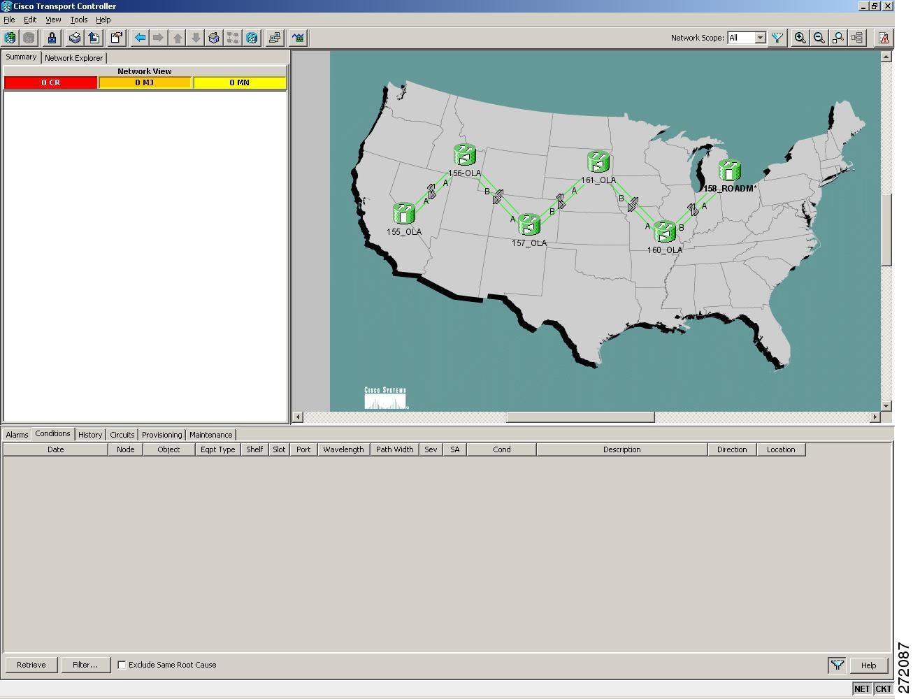
The Raman pump on the OPT-RAMP-C card can be configured on a single span or multiple spans.
Step 3 To start the Raman installation wizard, complete one of the following steps:
- To configure Raman amplification on a single span, go to Network view, right-click on a single node and choose Raman Installation Day0 from the shorcut menu. (Figure 6-2). Go to Step 5.
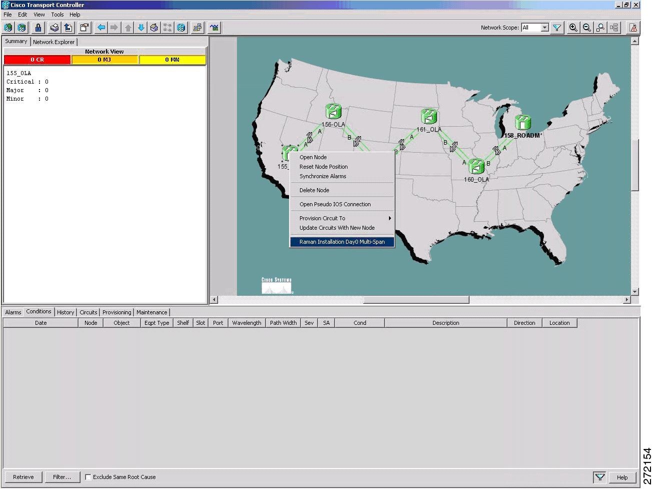
- To configure Raman amplificaion on multi-spans, go to Network view, right-click on a specific span, and choose Raman Installation Day0 Multi-span from the shorcut menu (Figure 6-3).
Figure 6-2 Installing the Raman Pump on a Single Span
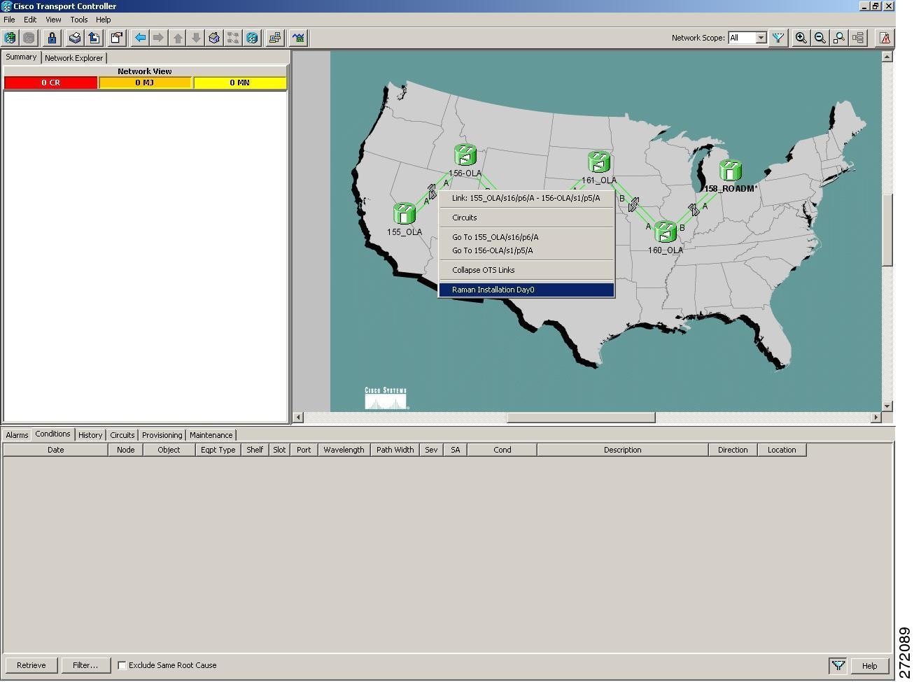
Figure 6-3 Installing the Raman Pump on a Multiple Spans
The Routing page is displayed (Figure 6-4).
Figure 6-4 Selecting Spans for Raman Amplification
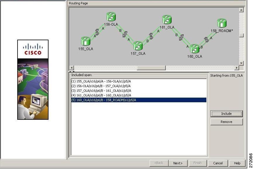
The Included Span list box lists all spans in the network.
Step 4 Select a span from the network to add a span.
If you are setting up multi-spans, make sure that the span selection is made in a sequence otherwise an error message is displayed. For example, in Figure 6-4, begin with the span between the nodes 155_OLA and 156_OLA, and then the span between 156_OLA and 157_OLA, and so on.
Step 5 When you have selected all span(s), click Next.
The Setting Parameters page is displayed (see Figure 6-5).
Figure 6-5 Setting Raman Calibration Parameter
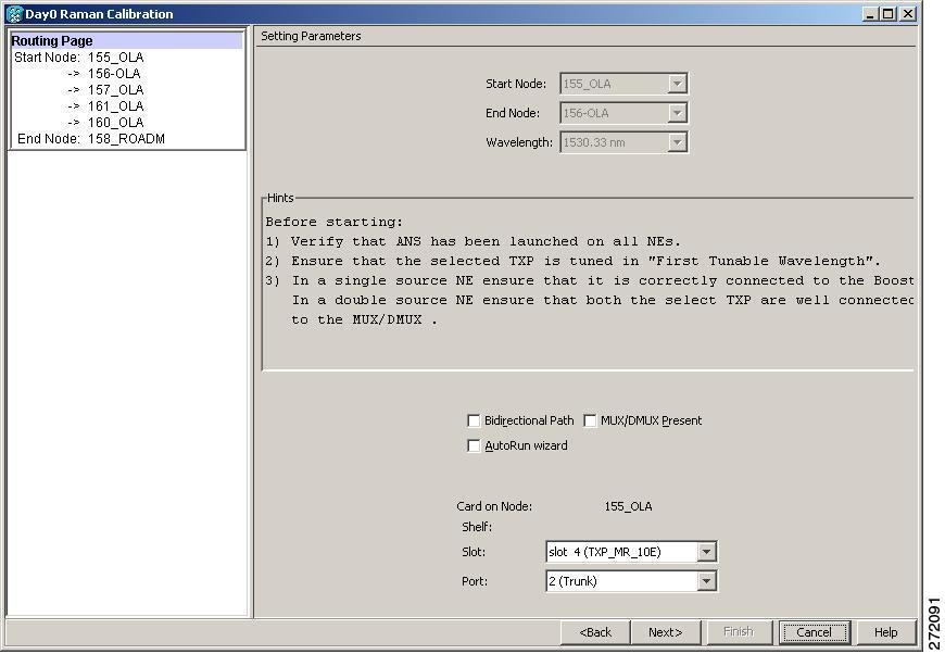
Note The Hints area displays the status of internal operations.
Note If multiple spans are selected, the applicable nodes are displayed on the left side of the page.
Step 6 Select AutoRun wizard checkbox. The Installation wizard executes a single or multiple span bidirectional circuit path automatically, requiring no user intervention. However, if the wizard displays errors, the wizard will request for user acknowledgements.
Step 7 Check the Bidirectional Path checkbox. This configures the OPT-RAMP-C cards in both directions (source to destination and destination to source). Several scenarios are discussed in the following section. Select as applicable:
- Check boxes Bidirectional Path is unchecked and MUX/DMUX Present is checked—See Figure 6-6 and Step 9.
- Check boxes Bidirectional Path is unchecked and MUX/DMUX Present is unchecked—See Figure 6-7 and Step 10.
- Check boxes Bidirectional Path is checked and MUX/DMUX Present is checked—See Figure 6-8 and Step 12.
- Check boxes Bidirectional Path is checked and MUX/DMUX Present is unchecked—See Figure 6-9 and Step 14.
Note Before you check the MUX/DMUX Present check box ensure that the following prerequisites are completed:
- At least one source node is a Terminal node or a ROADM node.
- Two transponder/muxponders supporting wavelength of 1530.33 nm and 1560.61 nm, used as probe signals are available on the source node.
- Trunk ports are connected to the correct ADD ports.
Note The Raman Wizard does not verify if the selected TXP connections are properly connected. The calibration process is terminated if an LOS-P alarm is detected on the MUX input port when the trunk port is turned on.
Note Before you uncheck the MUX/DMUX Present check box ensure that the following prerequisites are completed:
- Connect a UT2-based trunk port (from a transponder/muxponder card) to the COM-RX port of the booster amplifier on the source node.
A full-spectrum tunable interface allows the system to tune the signal on two required wavelengths without any human intervention.
- A 10 dB bulk attenuator must be connected between TXP trunk port and COM-RX port of the booster amplifier.
Note The MUX/DMUX Present check box can remain unchecked during troubleshooting a single span between two generic nodes, for example, to fix a fiber cut.
Make sure that the bulk attennuator is removed as soon as installation completes.
Figure 6-6 Bidirectional Path is Unchecked and MUX/DMUX Present is Checked
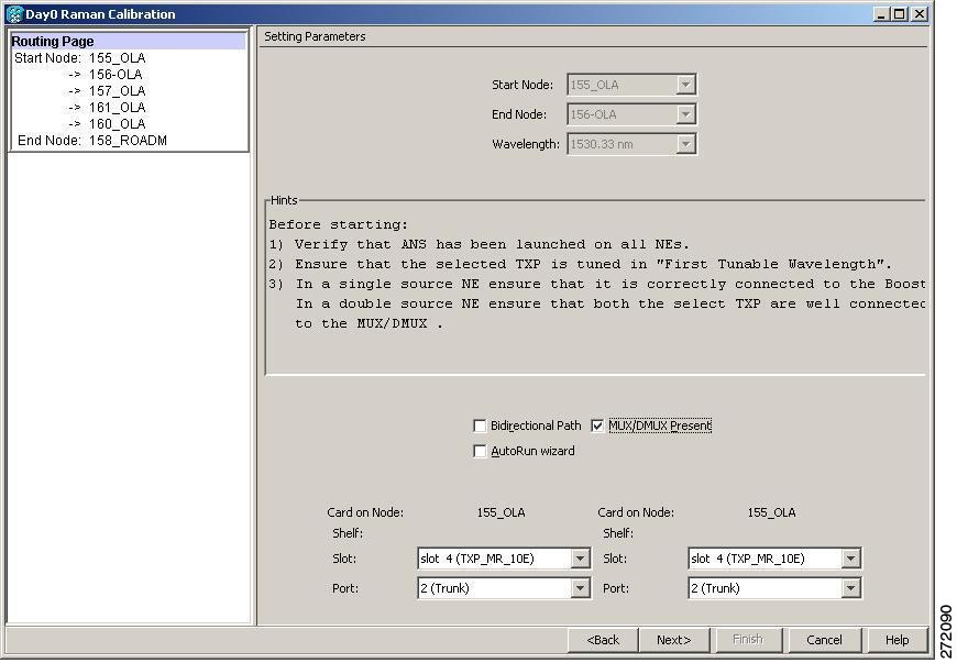
Step 8 Select the two transponders on the source node from the Slot drop-down list. The installation wizard verifies if the transponders are tuned to the expected wavelengths or the first tunable wavelength. Otherwise, the wizard fails and the installation must be repeated.
Step 9 Click Next. The Calibrate Raman Page is displayed (Figure 6-10).
Figure 6-7 Bidirectional Path is Unchecked and MUX/DMUX Present is Unchecked
Step 10 Select one transponder on the source node from the Slot drop-down list. The installation wizard verifies if the transponder can tune on the first tunable wavelength. Make sure that the transponder is a tunable C-band transponders. Otherwise, the wizard fails and the installation must be repeated and the installation must be repeated using a correctly configured tunable transponder.
Step 11 Click Next. The Calibrate Raman Page is displayed (Figure 6-10).
Figure 6-8 Bidirectional Path is Checked and MUX/DMUX Present is Checked
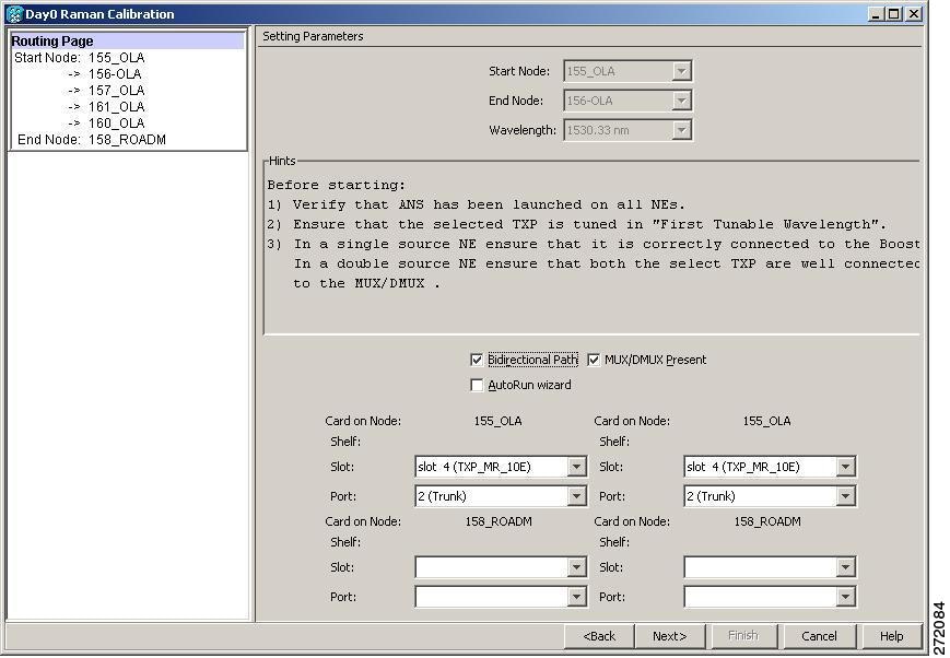
Step 12 Select the two transponders on source and destination node from the Slot drop-down list. The installation wizard verifies if the transponders are tuned to the expected wavelengths or on the first tunable wavelength. Otherwise, the wizard fails and the installation must be repeated.
Step 13 Click Next. The Calibrate Raman Page is displayed (Figure 6-10).
Figure 6-9 Bidirectional Path is Checked and MUX/DMUX Present is Unchecked
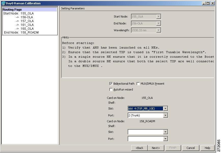
Step 14 Select a transponder on the source and destination node from the Slot drop-down list. The installation wizard verifies if the transponder can be tuned on the first tunable wavelength. Make sure that the transponder is a tunable C-band transponder. Otherwise, the wizard fails and the installation must be repeated.
Step 15 Click Next. The Calibrate Raman Page is displayed (Figure 6-10).
Figure 6-10 Calibrating Raman Amplification
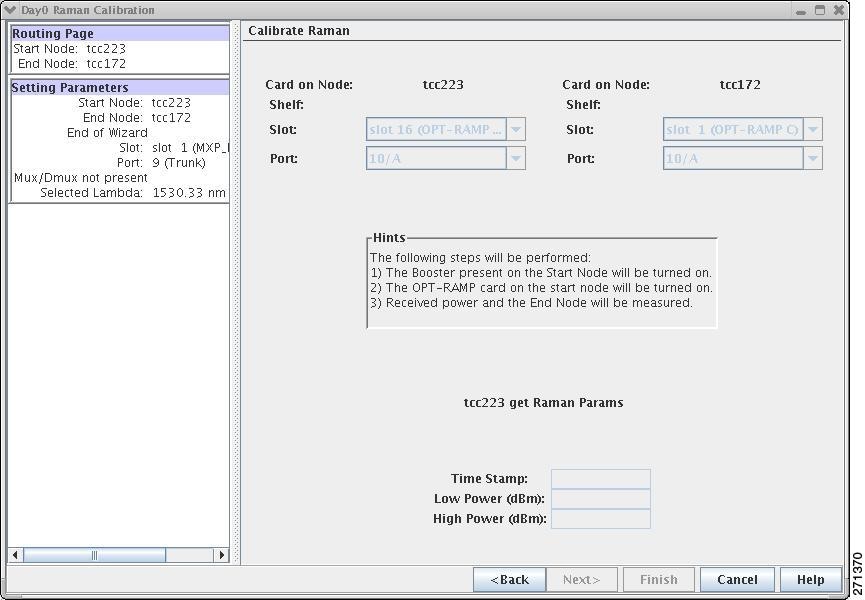
The installation wizard changes the trunk port to In-Service (IS) state and turns on all the amplifiers. All the OTS and optical channel (OCH) ports in the span are changed to IS state.
Step 16 As soon as the Raman calibrations are complete, the Next button is enabled. Click Next.
Figure 6-11 Calibrating Raman Amplification
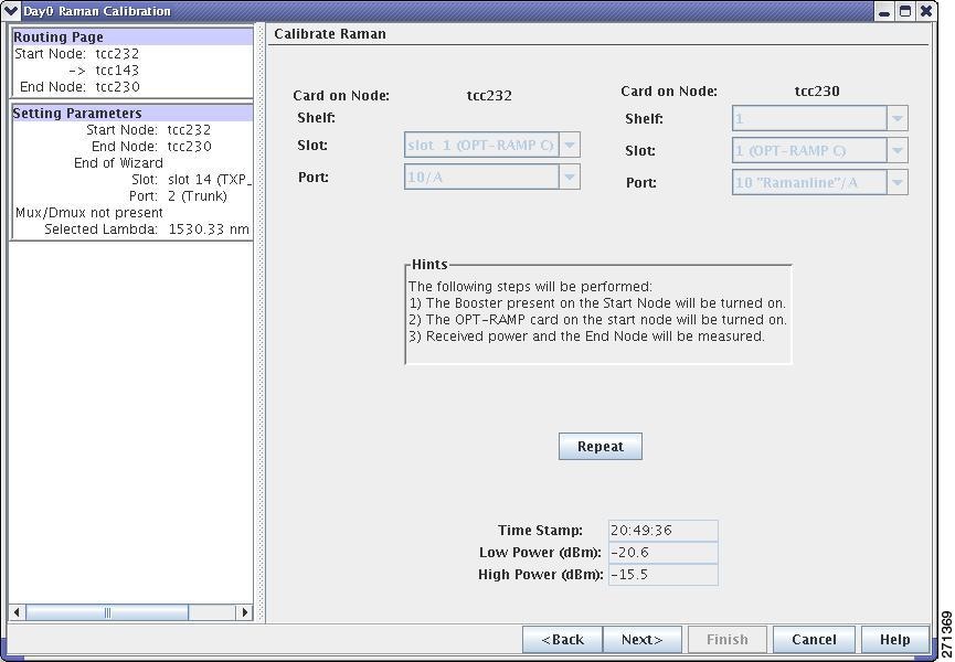
Step 17 The power received on destination node when wavelength on the source is turned on is shown. If you installed Raman amplification on multiple spans, click Next to view results of other spans.
Step 18 If the installation wizard fails, click the Repeat button. The Raman installation wizard recalibrates the values on the destination node.
Note If you have repeated the calibration several times and the wizard fails, press Cancel to abort the installation process. Log into the Technical Support Website at http://www.cisco.com/cisco/web/support/index.html for more information or call Cisco TAC at (800) 553-2447.
Step 19 Click Next. The Accept Results page is displayed (Figure 6-12).
Figure 6-12 Raman Amplification Results
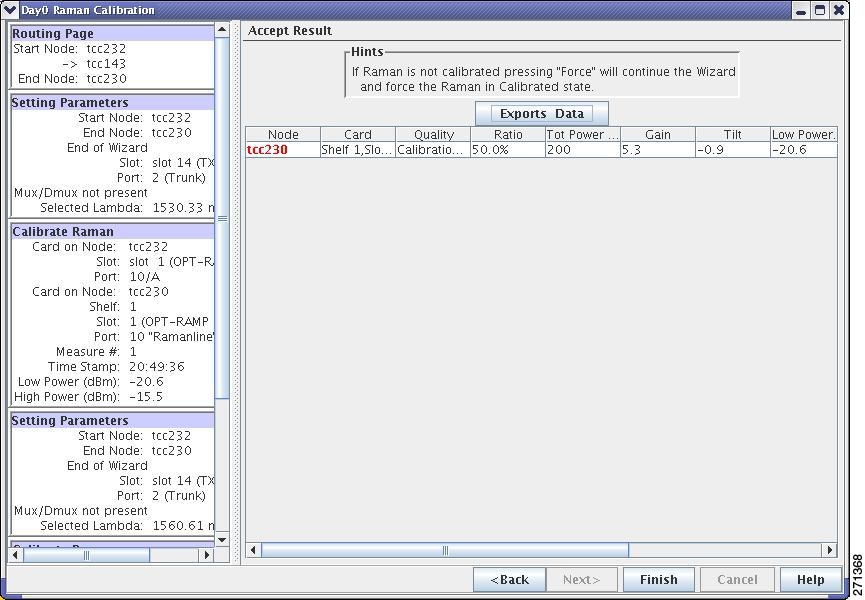
The calculated Raman power and Raman gain are displayed. (Figure 6-12).
Step 20 The wizard compares the calculated Raman gain value with the expected results. Your action depends on the Raman gain values.
- Expected gain (Gt) – 0.5 dB <= (gain) <= (expected gain) + 0.5 dB—If the Raman gain is within this range, it means that the setup procedure was successful (Figure 6-13). Click Next and Finish.
- 3.0 dB <= (gain) <= (expected gain) – 0.5 dB—If the Raman gain is within this range, it means that the values are slightly outside the range. The wizard will now recommend that you verify the span length and cabling, and repeat the installation wizard procedure. If the Raman gain values are still not within the expected value range even after repeating the installation process, you can choose to forcibly apply these values by clicking Force Calibration. However, Cisco recommends that you log into the Technical Support Website at http://www.cisco.com/cisco/web/support/index.html for more information or call Cisco TAC at (800) 553-2447.
- (gain) < (expected gain) – 3.0 dB or if (gain) < (expected gain) + 0.5 dB — If the Raman gain is within this range and the values calculated are far from the targeted results, the installation fails and the wizard recommends repeating the installation. If the results do not improve it means that the installation process has failed. The Force Calibration option is not available. Click Cancel to abort the installation and log into the Technical Support Website at http://www.cisco.com/cisco/web/support/index.html for more information or call Cisco TAC at (800) 553-2447.
Note The reason why the calculated values are not within the range may be due to installation issues (for example, the actual fiber type is different than the one used by Cisco Transport Planner to design the link) or procedural issues.
Step 21 Click Exports Data to export the Raman setup tuning data in text format.
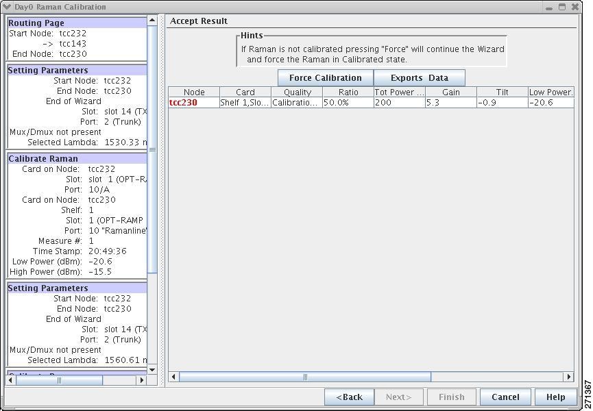
Note When an error occurs during calibration of multiple spans, the calibration process stops and the Force Calibration button becomes visible (Figure 6-13).
Note If an error occurs during calibration of multiple spans when using the AutoRun wizard, the calibration stops and the Force Calibration button becomes visible. (Figure 6-13). Click Force Calibration to force the results.
Figure 6-13 Force Raman Calibration
Step 23 Return to your originating procedure (NTP).
DLP-G474 Configure the Raman Pump by Loading the CTP XML File
This procedure configures the Raman Pump by loading the Cisco Transport Planner XML file. |
|
Note When the span is longer than 42 dB, do not use the Raman installation wizard.
Step 1 Install the ANS parameters calculated by the Cisco Transport Planner, by completing the G143 Import the Cisco TransportPlanner NE Update Configuration File.
Step 2 Launch, run, and apply ANS parameters by completing G37 Run Automatic Node Setup.
Step 3 In node view (single-shelf mode) or shelf view (multishelf mode), double-click the OPT-RAMP-C amplifier to display the card view.
Step 4 Click the Maintenance > APC & Restore tabs.
Step 5 Click Restore from Fiber Cut. This automatically restores the Raman gain on the other end of the span.
Stop. You have completed this procedure.
DLP-G489 Configure the Raman Pump by Setting the ANS Parameters Manually
This procedure configures the Raman Pump by setting the ANS parameters manually |
|
As needed, when the wizard fails and expert intervention is required. |
|
Note This procedure can be performed on a per-span basis only and not on multiple spans. To configure multiple spans, repeat the procedure on each span that you want to configure.
Running the installation wizard can result is traffic interruption. Make sure that nobody is working on the nodes before continuing with this procedure.
Step 1 Launch, run, and apply ANS parameters by completing G37 Run Automatic Node Setup.
Note The ANS parameters that must be manually provisioned in Step 1 are:
- Side i.Rx.Raman.Expected Raman Gain
- Side i.Rx.Raman.Expected Raman EDFA Per Channel Power
- Side i.Rx.Raman.Expected Raman Stage Output Power
- Side i.Rx.Raman.Raman Ratio
- Side i.Rx.Raman.Raman Power
ANS parameters are displayed in the Provisioning > WDM-ANS > Provisioning tab. For more information, see the “Node Reference” chapter in the Cisco ONS 15454 DWDM Reference Guide.
Step 2 Complete the G143 Import the Cisco TransportPlanner NE Update Configuration File.
Step 3 In node view (single-shelf mode) or shelf view (multishelf mode), double-click the OPT-RAMP-C card to go to the card view.
Step 4 Click the Maintenance > APC & Restore tabs. See Figure 6-14.
Figure 6-14 Restore from Fiber Cut
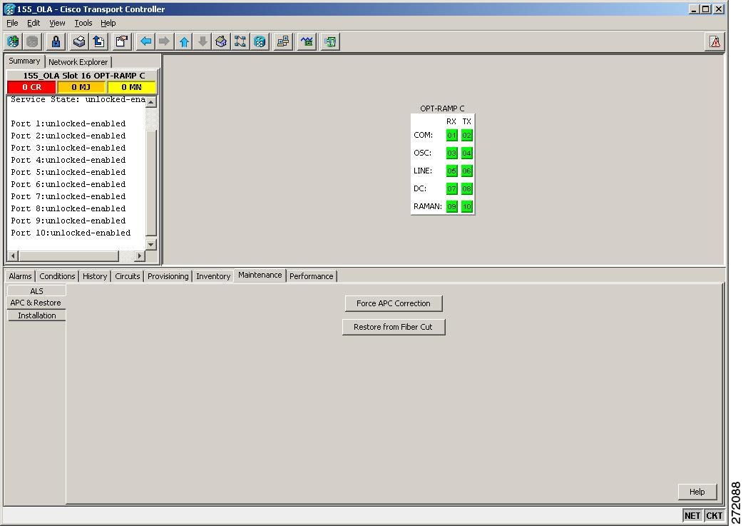
Step 5 This automatically restores the Raman gain on the other end of the span.
Step 6 Return to your originating procedure (NTP).
DLP-490 Restore Raman Link after a Fiber Cut Occurs
This procedure tunes Raman set-points after fiber cut has been repaired. The Raman total power value is calculated again and the original Raman gain is restored. |
|
Note This procedure does not calculate the Raman pump ratio. The Raman pump ratio is not expected to change after the fiber cut is repaired.
The procedure is traffic affecting. Make sure that nobody is working on the nodes before you begin.
Step 1 Complete the G54 Provision and Verify a DWDM Network.
Step 2 Make sure that the network traffic is restored.
Step 3 In node view (single-shelf mode) or shelf view (multishelf mode), double-click the OPT-RAMP-C amplifier to display the card view.
Step 4 Click the Maintenance > APC & Restore tabs.
Step 5 Click Restore from Fiber Cut. This automatically restores the Raman gain on the other end of the span.
Step 6 Return to your originating procedure (NTP).
Step 1 Complete the G46 Log into CTC at the node where you will set up timing. If you are already logged in, continue with Step 2.
Step 2 Complete the G95 Set Up External or Line Timing if an external building integrated timing supply (BITS) source is available. This is the most common ONS 15454 timing set-up method.
Step 3 If an external BITS source is not available, complete the G96 Set Up Internal Timing. This task can only provide Stratum 3 timing.
Step 4 Repeat this procedure at each node in the network.
Step 5 Return to your originating procedure (NTP).
DLP-G95 Set Up External or Line Timing
This task defines the ONS 15454 timing source (external or line). |
|
Step 1 In node view (single-node mode) or shelf view (multishelf mode), click the Provisioning > Timing > General tabs.
Step 2 In the General Timing area, complete the following information:
- Timing Mode—Choose External if the ONS 15454 derives its timing from a BITS source wired to the backplane pins (ANSI) or a MIC-C/T/P front mount electrical connection (FMEC) (ETSI); choose Line if timing is derived from an OSC-CSM or OSCM card that is optically connected to the timing node. A third option, Mixed, allows you to set both external and line timing references. Because Mixed timing might cause timing loops, Cisco does not recommend its use. Use this mode with care.
- SSM Message Set—Choose the Generation 2 synchronization status messaging (SSM) option. See the “Timing Reference” chapter in the Cisco ONS 15454 DWDM Reference Manual for more information about SSM, including definitions of the SONET timing levels.
Note Generation 1 is used only by SONET or SDH ONS 15454 nodes that are connected to equipment that does not support Generation 2.
- Quality of RES—Sets the timing quality for the user-defined, reserved (RES) S1 byte if your timing sources supports RES. Most timing sources do not use RES. If it does not support RES, choose RES=DUS (do not use for timing reference). Qualities are displayed in descending quality order as ranges. For example, in Generation 1 SSM, ST3<RES<ST2 means that the timing reference RES is higher than a Stratum 3 (ST3) and lower than a Stratum 2 (ST2).
- Revertive—Select this check box if you want the ONS 15454 to revert to a primary reference source after the conditions that caused it to switch to a secondary timing reference are corrected.
- Reversion Time—If Revertive is checked, choose the amount of time that the ONS 15454 will wait before reverting to its primary timing source. Five minutes is the default.
Step 3 In the Reference Lists area, complete the following information:
Note You can define up to three timing references for the node and up to six BITS Out references. BITS Out references define the timing references used by equipment that can be attached to the node’s BITS Out pins on the backplane (ANSI) or the MIC-C/T/P FMEC (ETSI). If you attach equipment to BITS Out pins, you normally attach it to a node with Line mode, because equipment near the external timing reference can be directly wired to the reference.
- NE Reference—Allows you to define three timing references (Ref 1, Ref 2, Ref 3). The node uses Reference 1 unless a failure occurs to that reference, in which case the node uses Reference 2. If Reference 2 fails, the node uses Reference 3, which is typically set to Internal Clock. Reference 3 is the Stratum 3 clock provided on the TCC2/TCC2P card. The options that appear depend on the Timing Mode setting.
– If the Timing Mode is set to External, your options are BITS-1, BITS-2, and Internal Clock.
– If the Timing Mode is set to Line, your options are the node’s working OSCM cards, OSC-CSM cards, transponder (TXP) cards, muxponder (MXP) cards, and Internal Clock. Choose the cards/ports that are directly or indirectly connected to the node wired to the BITS source. Set Reference 1 to the card that is closest to the BITS source. For example, if Slot 5 is connected to the node wired to the BITS source, choose Slot 5 as Reference 1.
– If the Timing Mode is set to Mixed, both BITS references and the OSCM, OSC-CSM, TXP, or MXP cards are available, allowing you to set a mixture of external BITS clocks and OSCM, OSC-CSM, TXP, or MXP cards as timing references.
- BITS-1 Out/BITS-2 Out—Sets the timing references for equipment wired to the BITS Out backplane (ANSI) or MIC-C/T/P FMEC (ETSI) pins. BITS-1 Out and BITS-2 Out are enabled when BITS-1 Out and BITS-2 Out facilities are put in service. If Timing Mode is set to external, choose the OSCM, OSC-CSM, TXP, or MXP card used to set the timing. If Timing Mode is set to Line, you can choose an OSCM, OSC-CSM, TXP, or MXP card or choose NE Reference to have the BITS-1 Out and/or BITS-2 Out follow the same timing references as the network element (NE).
Note All TXP or MXP card client ports are available for timing regardless of the card’s termination mode. TXP or MXP trunk ports can be a timing reference when ITU-T G.709 is set to OFF and the Termination Mode is set to LINE. You cannot choose TXP_MR_2.5G and OTU2_XP card client ports as timing reference.
Note The system prevents BITS In and BITS Out timing to be set on the same node.
Step 5 Click the BITS Facilities tab.
Note The BITS Facilities section sets the parameters for your BITS-1 and BITS-2 timing references. Many of these settings are determined by the timing source manufacturer. If equipment is timed through BITS Out, you can set timing parameters to meet the requirements of the equipment.
Step 6 In the BITS In area, complete the following information:
- Facility Type—(TCC2P card only) Choose the BITS signal type supported by your BITS clock, either DS1 or 64Khz+8Khz.
- BITS In State—If Timing Mode is set to External or Mixed, set the BITS In State for BITS-1 and/or BITS-2 to IS (in service) depending on whether one or both BITS input pin pairs are connected to the external timing source. If Timing Mode is set to Line, set the BITS In State to OOS (out of service).
Step 7 If the BITS In State is set to OOS, continue with Step 8. If the BITS In State is set to IS, complete the following information:
- Coding—Choose the coding used by your BITS reference, either B8ZS (binary 8-zero substitution) or AMI (alternate mark inversion).
- Framing—Choose the framing used by your BITS reference, either ESF (Extended Super Frame) or SF (D4) (Super Frame).
- Sync Messaging—Check this check box to enable SSM. SSM is not available if Framing is set to Super Frame.
- Admin SSM—If the Sync Messaging check box is not checked, you can choose the SSM Generation 2 type from the drop-down list. Choices are PRS (Primary reference source; Stratum 1), ST2 (Stratum 2), TNC (Transit Node Clock), ST3E (Stratum 3E), ST3 (Stratum 3), SMC (SONET minimum clock), and ST4 (Stratum 4).
Step 8 In the BITS Out area, complete the following information, as needed:
- Facility Type—(TCC2P only) Choose the BITS Out signal type, either DS1 or 64Khz+8Khz.
- BITS Out State—If equipment is connected to the node’s BITS output pins on the backplane (ANSI) or MIC-C/T/P FMEC (ETSI) and you want to time the equipment from a node reference, set the BITS Out State for BITS-1 and/or BITS-2 to IS, depending on which BITS Out pins are used for the external equipment. If equipment is not attached to the BITS output pins, set the BITS Out State to OOS.
Step 9 If the BITS Out State is set to OOS, continue with Step 10. If BITS Out State is set to IS, complete the following information:
- Coding—Choose the coding used by your BITS reference, either B8ZS or AMI.
- Framing—Choose the framing used by your BITS reference, either ESF or SF (D4).
- AIS Threshold—If SSM is disabled or Super Frame is used, choose the quality level where a node sends an alarm indication signal (AIS) from the BITS 1 Out and BITS 2 Out backplane pins (ANSI) or MIC-C/T/P FMEC (ETSI). An AIS alarm is raised when the optical source for the BITS reference falls to or below the SSM quality level defined in this field.
- LBO—If an external device is connected to the BITS Out pins, sets the line build-out (LBO) distance between the ONS 15454 and an external device. If an external device is connected to BITS Out, choose the distance between the device and the ONS 15454. Options are: 0-133 ft. (default), 134-266 ft., 267-399 ft., 400-533 ft., and 534-655 ft. Line build out (LBO) relates to the BITS cable length. If an external device is not connected to BITS Out, leave this field set to the default.
Note Refer to the Cisco ONS 15454 DWDM Troubleshooting Guide for timing-related alarms.
Step 11 Return to your originating procedure (NTP).
DLP-G96 Set Up Internal Timing
This task sets up internal timing (Stratum 3) for an ONS 15454. |
|
Internal timing is Stratum 3 and is not intended for permanent use. All ONS 15454 SONET (ANSI) or SDH (ETSI) nodes should be timed to a Stratum 2 or better primary reference source. Internal timing is appropriate for DWDM nodes.
Step 1 In node view (single-node mode) or shelf view (multishelf mode), click the Provisioning > Timing > General tabs.
Step 2 In the General Timing area, enter the following:
Step 3 In the Reference Lists area, enter the following information:
– Ref 1—Set to Internal Clock.
– Ref 2—Set to Internal Clock.
– Ref 3—Set to Internal Clock.
Step 5 Click the BITS Facilities tab.
Step 6 In the BITS Facilities area, change the BITS In State and BITS Out State to OOS for BITS 1 and BITS 2. Disregard the other BITS Facilities settings; they are not relevant to internal timing.
Step 8 Return to your originating procedure (NTP).
DLP-G350 Use the Cisco TransportPlanner Traffic Matrix Report
This task describes how to use the Cisco TransportPlanner traffic matrix report to provision and verify a DWDM network. |
|
Step 1 Display a printed copy of the Cisco TransportPlanner Traffic Matrix report for your network. Figure 6-15 shows an example of the Traffic Matrix report in Cisco TransportPlanner. The report can be exported in Microsoft Excel (.xls) or HTML format.
Figure 6-15 Cisco TransportPlanner Traffic Matrix Report
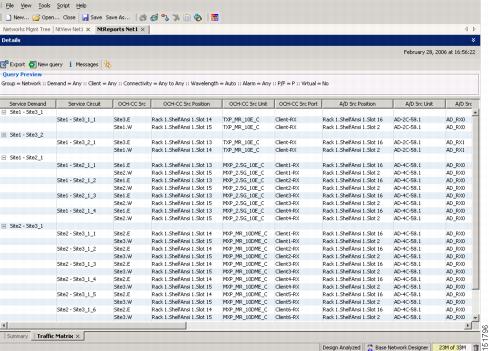
Step 2 View the following information:
- Service Demand—Lists the general service demand from site to site.
- Service Circuit—Lists the service circuit.
- OCH-CC Src—Lists the optical channel client connection (OCHCC) source site and the shelf direction, either Side B or Side A.
- OCH-CC Src Position—Lists the OCHCC source rack, shelf, and slot.
- OCH-CC Src Unit—Lists the OCHCC source TXP, MXP, or ITU-T line card.
- OCH-CC Src Port—Lists the OCHCC source port.
- A/D Src Position—Lists the optical channel add/drop card source rack, shelf, and slot.
- A/D Src Unit—Lists the optical channel add/drop card source TXP, MXP, or ITU-T line card.
- A/D Src Port—Lists the optical channel add/drop card source port.
- OCH-CC Dst—Lists the OCHCC destination site and shelf direction, either Side B or Side A.
- OCH-CC Dst Position—Lists the OCHCC destination rack, shelf, and slot.
- OCH-CC Dst Unit—Lists the OCHCC destination TXP, MXP, or ITU-T line card.
- OCH-CC Dst Port—Lists the OCHCC destination port.
- A/D Dst Position—Lists the optical channel add/drop card destination rack, shelf, and slot
- A/D Dst Unit—Lists the optical channel add/drop card destination TXP, MXP, or ITU-T line card.
- A/D Dst Port—Lists the optical channel add/drop card destination port.
– Dest Unit is the product ID of the optical path source card.
– Dest Port is the port label reported on the front panel of the optical path destination card.
– Optical paths for unprotected-Side B and unprotected-Side A optical channels are routed along one direction only in the network.
– Optical paths for Y-cable, fiber-switched, and client 1+1 optical channels are routed along two independent directions in the network.
Note If the word None appears in the Op Bypass Site Name column, no optical bypass is defined for the optical channel.
- Wavelength—Identifies the wavelength used for the optical channel. Table 7-2 lists the thirty-two available wavelengths.
- DWDM Interface Type—Identifies the DWDM interface type that is used for the optical channel:
– Transponder indicates that a transponder (TXP), muxponder (MXP), or DWDM pluggable port module is used for the optical channel.
– Line Card indicates that an ITU line card is used for the optical channel.
Step 3 Return to your originating procedure (NTP).
NTP-G54 Provision and Verify a DWDM Network
This procedure verifies the performance of all cable connections and cards in a network topology. You can also use this procedure to troubleshoot any problems with DWDM network set up. |
|
G277 Provision a Multirate PPM G278 Provision the Optical Line Rate G96 Provision the 10G Multirate Transponder Card Line Settings, PM Parameters, and Thresholds G97 Modify the 4x2.5G Muxponder Card Line Settings and PM Parameter Thresholds G98 Provision the 2.5G Multirate Transponder Card Line Settings and PM Parameter Thresholds G99 Modify the 2.5G Data Muxponder Card Line Settings and PM Parameter Thresholds G148 Modify the 10G Data Muxponder Card Line Settings and PM Parameter Thresholds |
|
Note In this procedure, Side A refers to Slots 1 through 6, and Side B refers to Slots 12 through 17.
Step 1 Complete the G46 Log into CTC to log into an ONS 15454 node on the network.
a. Verify that the alarm filter is not turned on. See the G128 Disable Alarm Filtering as necessary.
b. Verify that no equipment (EQPT) alarms appear. If equipment failure alarms appear, investigate and resolve them before continuing. Refer to the Cisco ONS 15454 DWDM Troubleshooting Guide for procedures.
Step 3 Using the Cisco TransportPlanner Traffic Matrix (see Table 3-1) for your site, identify the first channel (ITU wavelength) to be provisioned. Use the TXP, MXP, or line card that corresponds to the selected wavelength.
Step 4 For the ITU wavelength identified in Step 3, create an optical channel client connection (OCHCC) or optical channel network connection (OCHNC) circuit using one of the following tasks:
- G346 Provision Optical Channel Client Connections.
- G105 Provision Optical Channel Network Connections.
.After creating the OCHCC or OCHNC circuit, return to this procedure and continue with Step 5.
Note Every time a channel is created in the DWDM network, the amplifiers automatically calculate the optical output power needed to maintain a constant power level on each channel. Automatic power control (APC) also starts every 60 minutes. If the span length changes, APC modifies amplifier gains and modifies express variable optical attenuation (VOA). For more information about APC, refer to the “Network Reference” chapter in the Cisco ONS 15454 DWDM Reference Manual.
Step 5 In node view (single-shelf mode) or multishelf view (multishelf mode), click the Circuits tab. Verify that the OCHCC or OCHNC created in Step 4 has a DISCOVERED status and an IS state. If so, continue with Step 6. If not, complete G183 Diagnose and Fix OCHNC and OCH Trail Circuits.
Step 6 Click the circuit and click Edit.
Step 7 In the Edit Circuit dialog box, click the State tab.
Step 8 In the Cross-Connections table, verify that the circuit path is correct and record all the nodes that appear in the Node column. The first node is the circuit source, and the last node is the circuit destination. If the circuit path is incorrect, delete the circuit and go back to Step 4 to create a new circuit.
Step 9 Display the circuit source node in node view (single-shelf mode), or shelf view (multishelf mode). If an OPT-PRE card or OPT-AMP-17-C card (operating in the preamplifier mode) is installed, complete the following steps. If not, continue with Step 10.
a. Display the OPT-PRE or OPT-AMP-17-C card in card view.
b. Click the Provisioning > Opt.Ampli.Line > Parameters tabs.
c. Check the value of the Port 2 (COM-TX) Signal Output Power:
– If the OPT-PRE or OPT-AMP-17-C card is not carrying traffic, the values will not match. Skip this step and go to Step 10.
– If the value is equal to or greater than the value shown in the Channel Power Ref table cell, continue with Step d .
– If the value is lower than the value shown in the Channel Power Ref table cell, contact your next level of support.
– SideA.Rx.Power.Add&Drop - Drop Odd Power (if a 40-WSS-C/40-WSS-CE and 40-DMX-C/40-DMX-CE card is installed).
d. If a second OPT-PRE or OPT-AMP-17-C card is installed, repeat Steps a through c for the second OPT-PRE card. If not, continue with Step 10.
Step 10 If an OPT-BST card or an OPT-AMP-17-C or OPT-AMP-L card (provisioned in OPT-PRE mode) is installed, complete the following steps. If not, continue with Step 11.
a. Display the OPT-BST, OPT-AMP-17-C, or OPT-AMP-L card in card view.
b. Click the Provisioning > Opt.Ampli.Line > Parameters tabs.
c. check the value of the Port 6 (COM-TX) Signal Output Power:
– If the OPT-BST, OPT-AMP-17-C, or OPT-AMP-L card is not carrying traffic, the values will not match. Skip this step and go to Step 11.
– If the value is equal to or greater than the value shown in the Channel Power Ref table cell, continue with Step d .
– If the value is lower than the value shown in the Channel Power Ref table cell, contact your next level of support.
d. If a second OPT-BST, OPT-AMP-17-C, or OPT-AMP-L is installed, repeat Steps a through c for the second OPT-BST, OPT-AMP-17-C, or OPT-AMP-L card. If not, continue with Step 11.
Step 11 If the node is a ROADM with 32WSS and 32DMX or 32DMX-O cards installed, or is a ROADM with 40-WSS-C/40-WSS-CE and 40-DMX-C/40-DMX-CE cards installed and the circuit is an Add/Drop circuit, complete the following steps. If neither scenario applies, continue with Step 12.
a. In node view (single-node mode) or multishelf view (multishelf mode) click the Provisioning > WDM-ANS > Provisioning tabs.
b. In the Selector area, double-click the one of the following parameters:
– 32DMX-0 card installed—Side A > Rx > Power > Band x > Ch y Drop Power where x = 1 through 8 and y = 1 through 32 for the band and channel carrying the circuit.
– 32DMX card installed—Side A > Rx > Power > Add&Drop - Drop Power
– 40-DMX-C/40-DMX-CE card installed —Side A > Rx > Power > Add&Drop - Drop Power
c. Record the value located in the Value table cell on the right for one of the following:
– SideA.Rx.Power.Band x.Ch y Drop Power (if a 32DMX-O card is installed)
– SideA.Rx.Power.Add&Drop - Drop Power (if a 32DMX card is installed)
If the value is not present, skip this step and continue with Step d .
d. Display the 32DMX card or 40-DMX-C/40-DMX-CE installed on Side A in card view.
e. Click the Provisioning > Optical Chn > Parameters tabs.
f. Locate the channel that carries the circuit and verify that the value in the Power column matches the value recorded in Step c , +/– 2 dB. If so, continue with Step g . If the value is lower, contact your next level of support.
Note If the 32DMX or 40-DMX-C/40-DMX-CE card is not carrying traffic, the values will not match and the verification must be skipped.
g. In node view (single-node mode) or multishelf view (multishelf mode) click the Provisioning > WDM-ANS > Provisioning tabs.
h. In the Selector area, click the Side A > Tx > Power > Add&Drop - Output Power parameters. Record the value under the Value column. If the value is not present, skip this step and continue with step i .
i. Display the 32WSS or 40-WSS-C/40-WSS-CE card installed on Side A in card view.
j. Click the Provisioning > Optical Chn: Optical Connector x > Parameters where x = the MPO connector (1 through 4) carrying 8 wavelengths.
k. Locate the CHAN-TX port, 1 through 32 for the 32WSS card (or 1 through 40 for the 40-WSS-C/40-WSS-CE card), that corresponds to the circuit and verify that the value in the Power column matches the value recorded in step e ., +/– 1 dB. If the value is lower, contact your next level of support.
Note Note If the 32WSS or 40-WSS-C/40-WSS-CE card is not carrying traffic, the values will not match and the above check must be skipped.
l. Repeat steps from b through k for cards that are installed on Side B.
m. Continue with Step 13.
Step 12 If the node is a ROADM with 32WSS and 32DMX cards installed (or a ROADM with 40-WSS-C/40-WSS-CE and 40-DMX-C/40-DMX-CE cards installed), and the circuit is a pass-through circuit, complete the following steps. If neither scenario applies, continue with Step 13.
a. In node view (single-node mode) or multishelf view (multishelf mode), click the Provisioning > WDM-ANS > Provisioning tabs.
b. In the Selector area, double-click the Side A > TX > Power parameters. Record the value in the Power.Add&Drop - Output Power Value column. If the value is not present, skip this step and continue with Step c .
c. Display the 32WSS or 40-WSS-C/40-WSS-CE card installed on Side A in card view.
d. Click the Provisioning > Optical Chn: Optical Connector x > Parameters where x = the MPO connector (1 through 4) carrying 8 wavelengths. For the 40-WSS-C/40-WSS-CE card, x = the MPO connector (1 through 5) carrying 8 wavelengths.
e. Locate the port (CHAN-TX), (33 through 64 for the 32WSS or 41 through 80 for the 40-WSS-C/40-WSS-CE), that corresponds to the circuit and verify that the value in the Power column matches the value recorded in step b , +/– 1 dB. If the value is lower, contact your next level of support.
Note Note If the 32WSS or 40-WSS-C/40-WSS-CE card is not carrying traffic, the values will not match and the verification must be skipped.
f. Repeat steps a through e or the cards installed on Side B of the node.
Step 13 Check the received power range:
a. Navigate to the node where the first TXP, MXP, or line card is installed.
b. Display the TXP, MXP, or line card in card view.
c. Complete the G136 Clear Selected PM Counts.
d. Click the Performance > Optics PM tabs.
e. Record the values shown in the RX Optical Pwr field.
f. Click the Provisioning > Optics Thresholds tabs.
g. Verify that the value in Step e falls between the values shown for the RX Power High and RX Power Low. If so, continue with Step 14. If not, complete one of the following.
– Power lower than range—Clean the trunk fiber at the patch panel and on the TXP or MXP card. Repeat Steps e through g . If the power is still too low, contact your next level of support.
– Power higher than range—Add attenuation to the fiber and repeat Steps e through g . If the power still does not fall within the range, contact your next level of support.
Step 14 Perform a short-term bit error rate (BER) test:
a. Complete the G136 Clear Selected PM Counts for the TXP, MXP, or line card.
b. Display the TXP, MXP, or line card in card view.
c. Click the Performance > Payload PM tabs, or, if OTN is provisioned, the Performance > OTN PM tabs.
d. Perform a short-term BER test using a test signal from a test set or protocol analyzer.
e. Monitor the payload performance monitoring (PM) for at least 10 minutes for errors.
Note To see an accurate PM count, the BER test results must be consistent with the transmitted bit rate for at least 10 minutes.
Note For information about using a test set or protocol analyzer, refer to the test set or protocol analyzer user guide.
Step 15 In node view (single-node mode) or multishelf view (multishelf mode), display the next node in the circuit path identified in Step 8.
Step 16 Repeat Steps 9 through 14 for all nodes in the circuit path (one by one). Complete the steps for the circuit destination node last.
Step 17 Switch to network view and click the Circuits tab.
Step 18 Create a new OCHNC or OCHCC circuit for the next ITU wavelength listed in the Traffic Matrix report using one of the following tasks:
- G346 Provision Optical Channel Client Connections
- G105 Provision Optical Channel Network Connections
Step 19 After the circuit status is DISCOVERED and its state is IS, click the circuit and then click Edit.
Step 20 In the Edit Circuit dialog box, click the State tab.
Step 21 In the Cross-Connections table, verify that the circuit path is correct and record all the nodes that appear in the Node column. These are the nodes that are in the circuit path. The first node is the circuit source, and the last node is the circuit destination. If the circuit path is incorrect, delete the circuit and go back to Step 18 to create a new circuit.
Step 22 Complete Steps 9 through 14 for nodes in Step 21 that:
For all the remaining nodes, no further checks are needed.
Step 23 Repeat Steps 9 through 22 for all OCHCC or OCHNC circuits listed in your Traffic Matrix report. If a node fails any test, verify the setup and configuration and then repeat the test. If the test fails again, refer to the next level of support.
After all tests are successfully completed and no alarms exist in the network, the network is ready for service.
Stop. You have completed this procedure.
This procedure verifies the optical signal-to-noise ratio (OSNR). The OSNR is the ratio between the signal power level and the noise power level. |
|
Step 1 Complete the G46 Log into CTC at an ONS 15454 on the network.
Step 2 Using an optical spectrum analyzer, check the received OSNR for each transmitted channel on both ends of the span. Identify the last OSC-CSM, OPT-PRE, or OPT-BST MON port that the channel passes through before it is dropped.
Note The OPT-PRE reference also applies to the OPT-AMP-17-C card operating in OPT-PRE mode and the OPT-BST reference also applies to the OPT-AMP-17-C card operating in OPT-LINE mode.
Step 3 If OPT-PRE cards are installed with an OPT-BST, OPT-BST-E, or OSC-CSM card, use the OPT-PRE MON port.
Note For OSNR values for each card class, refer Chapter 4, “Optical Amplifier Cards.”
Step 4 If the OSNR is too low, check the following, depending on your node configuration:
Note The purpose of this step is not to improve the signal-to-noise ratio (SNR), but to match the per-channel power level within the RX port power range.
- Check the fiber connections between the OPT-BST, OPT-BST-E, or OSC-CSM card and the OPT-PRE amplifier. If needed, clean the connectors. See the G115 Clean Fiber Connectors.
- On the near-end OPT-BST amplifier, check the equalization of the added channels at the monitor output.
- On the OPT-PRE amplifier, check the output power on both COM TX and DC TX ports.
- On the far-end OPT-PRE amplifier, check the amplifier gain tilt at the monitor output.
If the OSNR is still too low, contact your next level of support.
Step 5 Repeat Steps 2 and 4 for all traffic in the network.
Stop. You have completed this procedure.
NTP-G142 Perform a Protection Switch Test
Step 1 Complete the G46 Log into CTC at an ONS 15454 on the network.
Step 2 Identify the Y-cable circuit to be tested by viewing the Traffic Matrix for your site. Locate the TXP, MXP, GE_XP, 10GE_XP, GE_XPE, 10GE_XPE, and/or OTU2_XP cards in the ONS 15454 node that will be used for the protection group.
Step 3 Verify that the Y-cable protection group is provisioned:
a. In node view (single-node mode) or multishelf view (multishelf mode), click the Provisioning > Protection tabs.
b. In the Protect and Working areas, confirm that the correct TXP, MXP, GE_XP, 10GE_XP, GE_XPE, 10GE_XPE, and/or OTU2_XP cards are in the Y-cable protection group by viewing the slot number and card type.
c. If the required protection group is not provisioned, stop and perform the G33 Create a Y-Cable Protection Group. Otherwise continue with Step 4.
Step 4 Repeat Step 3 for each Y-cable protection group at the node. When all protection groups are verified, continue with the next step.
Step 5 Physically connect the transmitter of the client or test set to either Port 10 or Port 12 of the Y-cable module protecting the test circuit. (See Table 3-6 and Table 3-7.)
Step 6 If you connected the transmitter to Port 10, connect the client or test set receiver to Port 5 on the Y-cable module. If not, connect the client or test set receiver to Port 11 on the Y-cable module.
Step 7 At the far-end site for the test circuit, physically loop the Y-cable module as follows:
a. If this is the first client on the Y-cable module, loop Port 10 to Port 5 on the far-end Y-cable module.
b. If this is the second client on the Y-cable module, loop Ports 11 and 12 on the far-end Y-cable module.
Step 8 At the near-end site for the test circuit, place the client device or test set into service and begin transmitting the required payload.
Step 9 In CTC, display the near-end site in node view (single-node mode) or multishelf view (multishelf mode).
Step 10 Click the Maintenance > Protection tabs (Figure 6-16).
Figure 6-16 Maintenance > Protection Tabs
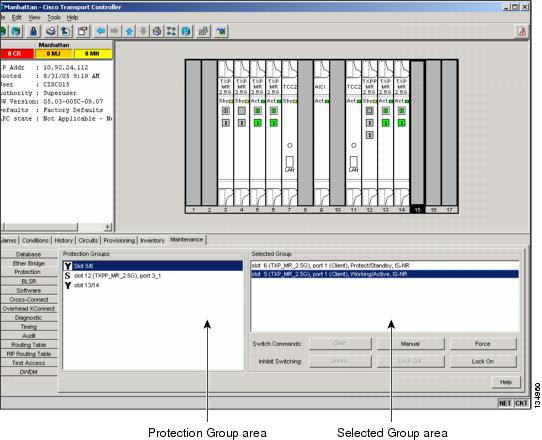
Step 11 In the Protection Groups area, highlight the protection group to be tested.
Step 12 In the Selected Group area, identify the slot that is Active and the slot that is Standby.
Step 13 Verify that the LED s on the physical cards in the shelf match the following:
a. For the Active TXP, MXP, GE_XP, 10GE_XP, GE_XPE, 10GE_XPE, or OTU2_XP card, record the slot number: _____. Verify that the port LEDs appear as follows:
b. For the Standby TXP, MXP, GE_XP, 10GE_XP, GE_XPE, 10GE_XPE, or OTU2_XP card, record the slot number: _____. Verify that the port LEDs appear as follows:
– Client port is not illuminated or amber, depending on the TXP, MXP, GE_XP, 10GE_XP, GE_XPE, 10GE_XPE, or OTU2_XP card.
Step 14 In the Selected Group area, highlight the active TXP, MXP, GE_XP, 10GE_XP, GE_XPE, 10GE_XPE, or OTU2_XP slot.
Step 15 From the Switch Commands area below the Selected Group area, click Manual, then click YES.
Step 16 From the Selected Group area, record the following information and verify that the active and standby TXP, MXP, GE_XP, 10GE_XP, GE_XPE, 10GE_XPE, or OTU2_XP slot numbers are the opposite of Step 13.
a. For the Active TXP, MXP, GE_XP, 10GE_XP, GE_XPE, 10GE_XPE, or OTU2_XP card, record the slot number: _____. Verify that the port LEDs appear as follows:
b. For the Standby TXP, MXP, GE_XP, 10GE_XP, GE_XPE, 10GE_XPE, or OTU2_XP card, record the slot number: _____. Verify that the port LEDs appear as follows:
– Client port is not illuminated or amber, depending on the TXP, MXP, GE_XP, 10GE_XP, GE_XPE, 10GE_XPE, or OTU2_XP card.
Step 17 Verify that the LEDs on the physical cards in the shelf match the following:
a. For the Active TXP, MXP, GE_XP, 10GE_XP, GE_XPE, 10GE_XPE, or OTU2_XP slot LEDs:
b. For the Standby TXP, MXP, GE_XP, 10GE_XP, GE_XPE, 10GE_XPE, or OTU2_XP slot LEDs:
– Client port is not illuminated.
Step 18 Confirm that the client or test set at the local site is operating normally without alarms. If the test set is reporting active alarms, contact your next level of support.
Note It is normal to see a traffic hit on the test set during a protection switch.
Step 19 From the Switch Commands area below the Selected Group area, click Clear, then click YES to return the protection group to the original state.
Step 20 Repeat Steps 5 through 19 for each protection group at your site.
Stop. You have completed this procedure.
NTP-G164 Configure Link Management Protocol
This procedure configures Link Management Protocol (LMP). LMP manages the channels and links that are required between nodes for routing, signaling, and link management. |
|
Note This procedure is normally required only when the Cisco ONS 15454 must run traffic to and from a Calient PXC or a CRS-1 router.
Step 1 Complete the G46 Log into CTC to log into an ONS 15454 on the network.
Step 2 To enable LMP, complete the G372 Enable LMP.
Step 3 To set up one or more control channels, complete the G373 Create, Edit, and Delete LMP Control Channels.
Step 4 To set up one or more traffic engineering (TE) links, complete the G374 Create, Edit, and Delete LMP TE Links.
Step 5 To set up one or more data links, complete the G378 Create, Edit, and Delete LMP Data Links.
Stop. You have completed this procedure.
Step 1 In node view, click the Provisioning > Comm Channels > LMP > General tabs.
Step 2 In the Configuration area, click the Enable LMP check box to enable the LMP function.
Step 3 In the Local Node Id text entry box, enter the local node ID in the form of an IP address.
Note Do not set the LMP Local Node ID to another IP address in use on the network. This introduces a duplicate IP address in the network for traffic going to the IP address that is used as the LMP Local Node ID. It is recommended to set the LMP Local Node ID to the node's IP address since this will not introduce a duplicate IP address in the network.
Step 4 If you are going to use LMP to manage a control channel between a Calient PXC node and a
Cisco ONS 15454 DWDM node or between a Cisco CRS-1 router and Cisco ONS 15454 DWDM node, ensure that the LMP-WDM check box is unchecked.
Step 5 If you are going to use LMP to manage a control channel between ONS 15454 nodes, check the LMP-WDM check box and use the Role field to choose either PEER or OLS.
The role selection is only available when LMP-WDM is enabled on the local node. Both the local and remote nodes must be configured with LMP-WDM enabled.
Step 7 In the Status area, verify that the Operational State is Up. This indicates that LMP is enabled and the link is active.
Step 8 Return to your originating procedure (NTP).
DLP-G373 Create, Edit, and Delete LMP Control Channels
Step 1 In node view, click the Provisioning > Comm Channels > LMP > Control Channels tabs.
Step 2 To create a control channel, click Create. The Create LMP Control Channel dialog box appears (Figure 6-17).
Note The values of the Admin State, Requested Hello Interval, Min Hello Interval, Max Hello Interval, Requested Hello Dead Interval, Min Hello Dead Interval, and Max Hello Dead Interval fields correspond to the values specified for these fields in the NODE > lmp section of the node view Provisioning > Defaults tabs. If you change the NODE > lmp values, those values are reflected as defaults in the Create LMP Control Channel dialog box (Figure 6-17). You can change the default values using the dialog box. However, the NODE > lmp values are always used as the initial defaults.
Figure 6-17 Create LMP Control Channel Dialog Box
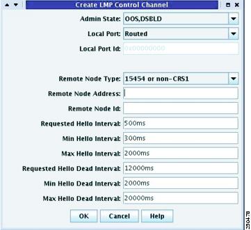
Step 3 In the Create LMP Control Channel dialog box, complete the following:
- Admin State—Select unlocked (if you are using an ETSI shelf) or IS (if you are using an ANSI shelf) to establish the control channel; otherwise, select locked, disabled (ETSI) or OOS-DSBLD (ANSI) to set the control channel to out of service.
- Local Port—Select Routed if the control channel is to be sent over the control plane or management network; otherwise, if the control channel is to be sent over the same fiber as the traffic (either in the payload or in the overhead), select one of the available traffic ports.
- Local Port Id—(Display only) Displays the local port identifier assigned by the node.
- Remote Node Type—Select 15454 or non-CRS1 if you are creating control channel between two Cisco ONS 15454 nodes or between a Calient PXC and a Cisco ONS 15454 node; otherwise, select CRS-1 if you are creating control channel between a CRS-1 router and a Cisco ONS 15454 node.
- Remote Node Address—In dotted decimal format, enter the number that identifies the IP address of the remote node (either a Calient PXC peer node, a CRS-1 router, or a Cisco ONS 15454 node) where the control channel will be established.
- Remote Node ID—Initially, CTC autopopulates this value to the Remote Node IP Address that you just assigned. However, you can change the identifier to any non-zero 32-bit integer in dotted decimal format (for example, 10.92.29.10).
- Requested Hello Interval—Enter the Requested Hello Interval in milliseconds (ms). Before sending Hello messages, the HelloInterval and Hello Dead Interval parameters must be established by the local and remote nodes. These parameters are exchanged in the Config message. The Hello Interval indicates how frequently LMP Hello messages will be sent; the interval must be in the 300 ms to 5000 ms range. The Min Hello Interval must be less than or equal to the Requested Hello Interval and the Requested Hello Interval must be less than or equal to the Max Hello Interval.
- Min Hello Interval—Enter the minimum Hello Interval in milliseconds. When the two nodes negotiate for the Hello Interval, the value you enter here will be the minimum Hello Interval acceptable for the local node. The Min Hello Interval must be in the 300 ms to 5000 ms range. The Min Hello Interval must be less than or equal to the Requested Hello Interval and the Requested Hello Interval must be less than or equal to the Max Hello Interval.
- Max Hello Interval—Enter the maximum Hello Interval in milliseconds. When the two nodes negotiate for the Hello Interval, the value you enter here will be the maximum Hello Interval acceptable for the local node. The Max Hello Interval must be in the 300 ms to 5000 ms range. The Min Hello Interval must be less than or equal to the Requested Hello Interval and the Requested Hello Interval must be less than or equal to the Max Hello Interval.
- Requested Hello Dead Interval—Enter the Requested Hello Dead Interval in milliseconds. The Requested Hello Dead Interval indicates how long a device should wait to receive a Hello message before declaring a control channel dead. The Requested Hello Dead interval must be in the 2000 ms to 20000 ms range. The Min Hello Dead Interval must be less than or equal to the Requested Hello Dead Interval and the Requested Hello Dead Interval must be less than or equal to the Max Hello Dead Interval.
Note The Requested Hello Dead Interval must be at least three times greater than the Requested Hello Interval.
- Min Hello Dead Interval—Enter the minimum Hello Dead Interval in milliseconds. The minimum Hello Dead Interval must be in the 2000 ms to 20000 ms range. The minimum Hello Dead Interval must be less than or equal to the Requested Hello Dead Interval and the Requested Hello Dead Interval must be less than or equal to the Max Hello Dead Interval. When the two nodes negotiate for the Hello Dead Interval, the value you enter here will be the minimum Hello Dead Interval acceptable for the local node.
Note The value of the Min Hello Dead Interval must be greater than the Min Hello Interval.
- Max Hello Dead Interval—Enter the maximum Hello Dead Interval in milliseconds. This interval must be in the 2000 ms to 20000 ms range. The Min Hello Dead Interval must be less than or equal to the Requested Hello Dead Interval and the Requested Hello Dead Interval must be less than or equal to the Max Hello Dead Interval. When the two nodes negotiate for the Hello Dead Interval, the value you enter here will be the maximum Hello Dead Interval acceptable for the local node.
Note The Max Hello Dead Interval must be greater than the Max Hello Interval.
Step 4 Click OK to accept the parameters you have entered, or click Cancel to return to the Control Channels tab without creating a control channel.
Step 5 If you created a control channel, verify that the parameters for the new Control Channel appear properly in the Control Channels tab.
Note The Actual Hello Interval and Actual Hello Dead Interval parameters reflect the values of these parameters as a result of the negotiated agreement of the local and remote nodes. They may be different than the requested values.
Step 6 After the LMP control channel has been created, observe the status of the channel in the Operational State column of the Control Channels tab, and take the appropriate action as shown in the following list:
- Up: The control channel contacted the far-end node and successfully negotiated a control channel.
- Down: LMP is enabled and the link is inactive. Ensure that the Admin State of the control channel is unlocked (ETSI) or IS (ANSI) and not disabled (ETSI) or OOS-DSBLD (ANSI). If the state still does not transition to Up, the far-end control channel might have disjointed Hello negotiation times that prevent a control channel from transitioning to the Up state. For example, the local ONS 15454 Min Hello Interval and Max Hello Interval might be 900 to 1000, while the remote Min Hello Interval and Max Hello Interval is 1100 to 1200.
- Config Send: The connection could not be made to the remote node. Check to make sure the Remote Node address and Remote Node ID addresses are correct.
- Config Received: The local node sent a configuration request to the remote node and received a response of either ConfigNack or ConfigAck.
- Unknown
Step 7 To delete a control channel, click the channel row to highlight it and click Delete. A confirmation dialog box appears that allows you to click OK or Cancel.
Step 8 To edit a control channel, click the channel row to highlight it and click Edit. A dialog box similar to Figure 6-17 appears that allows you to change the control channel parameters. You can then click OK or Cancel.
Step 9 Return to your originating procedure (NTP).
DLP-G374 Create, Edit, and Delete LMP TE Links
This task creates, edits, or deletes TE links and their association to neighboring LMP nodes. |
|
Step 1 In node view, click the Provisioning > Comm Channels > LMP > TE Links tabs.
Step 2 To create a TE link, click Create. The Create LMP TE Link dialog box appears (Figure 6-18).
Figure 6-18 Create LMP TE Link Dialog Box
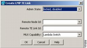
Step 3 In the Create LMP TE Link dialog box, complete the following:
- Admin State—Select unlocked (for ETSI shelves) or IS (for ANSI shelves) to put the TE link in service; otherwise, select locked, disabled (ETSI) or OOS-DSBLD (ANSI) to set the TE link to out of service.
- Remote Node Id—Select a remote node (either a Calient PXC peer node, a CRS-1 router, or a Cisco ONS 15454 node) for the other end of the TE link.
- Remote TE Link Id—Enter an unsigned 32-bit value (such as 0x00000001) to identify the remote node identifier for the other end of the TE link.
- MUX Capability—Select Lambda Switch. Even though there are other choices, you must choose Lambda Switch because the ports that can be selected are restricted to DWDM client ports, which means they are lambda switched onto the DWDM trunk port for transport across the DWDM network.
Step 4 Click OK to accept the parameters you have entered and create the TE link, or click Cancel to return to the Control Channels tab without creating a TE link.
Step 5 If you created a TE link, verify that the parameters for the new TE link now appear properly in the TE Links tab.
Step 6 After the TE link has been created, observe the status of the TE link in the Operational State column of the TE Links pane, and take the appropriate action as shown in the following list:
- Up: The TE link is active.
- Down: Ensure that the Admin State of the TE link is unlocked (ETSI) or IS (ANSI) and not disabled (ETSI) or OOS-DSBLD (ANSI). The TE link will not transition to the Up state until a data link has been provisioned.
- Init: Verify that the Remote Node ID and Remote TE Link ID values are correct for the remote node. Verify that the remote node is using the Cisco ONS 15454 or the CRS-1 router IP address for its remote node IP and that the remote node is using the local TE link index for its remote TE link index.
Step 7 To delete a TE link, click the link row to highlight it and click Delete. A confirmation dialog box appears that allows you to click OK or Cancel.
Step 8 To edit a TE link, click the link row to highlight it and click Edit. A dialog box similar to Figure 6-18 appears that allows you to change the TE link parameters. You can then click OK or Cancel.
Step 9 Return to your originating procedure (NTP).
DLP-G378 Create, Edit, and Delete LMP Data Links
This task creates, edits, or deletes one or more data links, which define the node’s transport parameters. CTC supports up to 256 LMP data links. |
|
Note A port cannot be deleted if it is being used by a data link. A card cannot be deleted if any of its ports are being used by data links. Changing the state of the port impacts the state of a data link using the port.
Step 1 In node view, click the Provisioning > Comm Channels > LMP > Data Links tabs.
Step 2 To create a data link, click Create. The Create LMP Data Link dialog box appears (Figure 6-19).
Figure 6-19 Create LMP Data Link Dialog Box
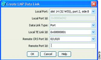
Step 3 In the Create LMP Data Link dialog box, complete the following:
- Local Port—Select one of the available local ports for the data link.
- Local Port Id—(Display only) The local port identifier.
- Data Link Type—Select Port or Component. A data link is considered to be either a port or a component link on each node where it terminates depending on the multiplexing capability of the endpoint on that link; component links are multiplex capable, whereas ports are not multiplex capable.
- Local TE Link Id—Select an identifier for one of the local TE links that has already been created.
- Remote CRS Port Id—Select one of the available remote CRS-1 ports for the data link. This option is not available if you are creating a data link between two Cisco ONS 15454 nodes.
- Remote Port Id—Enter an unsigned 32-bit value (such as 0x00000001) to identify the remote node identifier for the other end of the data link.
Step 4 Click OK to accept the parameters you have entered and create the data link, or click Cancel to return to the Data Links tab without creating a data link.
Step 5 If you created a data link, verify that the parameters for the new data link now appear properly in the Data Links tab.
Step 6 After the data link has been created, observe its status in the Operational State column of the Data Links tab, and take the appropriate action as shown in the following list:
- Up–Alloc or Up–Free: If the data link state does not transition to Up–Alloc or Up–Free, verify that the port is in service. Verification must be done using the CTC card view > Provisioning tab for the cards. (The difference between Up–Alloc and Up–Free is that an Up–Alloc data link is allocated for data traffic. An Up–Free data link is not allocated for traffic. The far end is either not ready to receive traffic through this port, or the path is being used as a backup in case some other allocated data link goes down).
- Down: The data link will be in the Down state if the port is not unlocked or not in-service. Verify that the remote port ID for the far-end data link is correct. On the far end, verify that the data link is using the Local Port Id as its remote port ID.
Step 7 To delete a data link, click the data link row to highlight it and click Delete. A confirmation dialog box appears that allows you to click OK or Cancel.
Step 8 To edit a data link, click the data link row to highlight it and click Edit. A dialog box similar to Figure 6-19 appears that allows you to change the data link parameters. You can then click OK or Cancel.
Step 9 Return to your originating procedure (NTP).
NTP-G207 Configure Link Management Protocol on CRS-1 Router and DWDM Node
This procedure configures LMP on a DWDM node and on the corresponding CRS-1 PLIM port. |
|
Note This procedure is normally required only when the Cisco ONS 15454 DWDM node must run traffic to and from a CRS-1 router. For more information on the Cisco IOS commands used in the DLPs, refer to the Cisco IOS Command Reference publication at http://www.cisco.com/en/US/products/ps5845/products_product_indices_list.html.
Step 1 Complete the G46 Log into CTC to log into a DWDM node on the network.
Step 2 Complete the G372 Enable LMP to enable the LMP function on the DWDM node.
Step 3 Complete the G373 Create, Edit, and Delete LMP Control Channels to create an LMP control channel between the CRS-1 router and the DWDM node.
Step 4 Complete the G374 Create, Edit, and Delete LMP TE Links to create TE links between the CRS-1 router and the DWDM node.
Step 5 In node view, click the Provisioning > Comm Channels > LMP > TE Links tab and write down the value of the Local TE Link field so that it can be used later.
Step 6 Complete the G378 Create, Edit, and Delete LMP Data Links to create a data link, which define the node’s transport parameters.
Step 7 In node view, click the Provisioning > Comm Channels > LMP > Data Links tab and write down the value of the Local Port Id field so that it can be used later.
Step 8 Complete the G481 Establish Telnet Session with CRS-1 Router and Verify Configuration to establish a Telnet session with the CRS-1 router.
Step 9 Complete the G482 Configure Static Route to configure a static route.
Step 10 Complete the G483 Configure Local and Remote TE Link to configure the local and remote TE links.
Step 11 Complete the G484 Enable LMP Message Exchange to enable LMP message exchange with an LMP neighbor.
Step 12 Complete the G494 Configure RADIUS Server to configure a RADIUS server.
Step 13 Complete the G485 Enable Index Persistency on SNMP Interface to enable index persistency on an SNMP interface.
Step 14 Complete the G486 Configure LMP Router ID to configure LMP router ID.
Step 15 Complete the G487 Configure 10 Gigabit Ethernet or POS Interface to configure an interface and specify the IPv4 address for the interface.
Step 16 Complete the G488 Display Summary of Link Management Information to display the interface resource or a summary of link management information.
Step 17 Complete the G374 Create, Edit, and Delete LMP TE Links to edit the TE link created in Step 4. Change the Remote TE Link ID value to the value (Local TE Link ID) noted in Step 1 of G488 Display Summary of Link Management Information.
Step 18 Complete the G378 Create, Edit, and Delete LMP Data Links to edit the data link created in Step 6. Change the Remote Port Id value to the value (Local Data Link ID) noted in Step 1 of G488 Display Summary of Link Management Information.
Stop. You have completed this procedure.
DLP-G481 Establish Telnet Session with CRS-1 Router and Verify Configuration
This task establishes a Telnet session with the CRS-1 router and verifies the SSH and/or XML module configuration. |
|
DLP-G482 Configure Static Route
G481 Establish Telnet Session with CRS-1 Router and Verify Configuration |
|
Note In the examples shown in this task, the IP address of the DWDM node is 10.58.41.22 and the IP address of the CRS-1 router is 10.58.41.169. To remove the static route configuration, use the no form of the IOS commands. For more information on the Cisco IOS commands, refer to the Cisco IOS Command Reference publication at http://www.cisco.com/en/US/products/ps5845/products_product_indices_list.html.
DLP-G483 Configure Local and Remote TE Link
This task explains how to configure the local and remote TE links. |
|
G481 Establish Telnet Session with CRS-1 Router and Verify Configuration |
|
Note In the examples shown in this task, the IP address of the DWDM node is 10.58.41.22 and the IP address of the CRS-1 router is 10.58.41.169. To remove the local and remote TE link configuration, use the no form of the IOS commands. For more information on the Cisco IOS commands, refer to the Cisco IOS Command Reference publication at http://www.cisco.com/en/US/products/ps5845/products_product_indices_list.html.
|
|
|
|
|---|---|---|
|
|
||
|
|
||
|
|
||
|
|
||
mpls traffic-eng interface interface-type interface-instance router(config)# mpls traffic-eng interface TenGigE 0/1/0/1
|
Enables MPLS-TE on an interface and enters MPLS-TE interface submode. Note The interface you specify for this command must be the optical interface related to the PLIM port involved in the LMP link. |
|
|
|
||
neighbor 10.58.41.22
|
||
remote te-link-id unnum identifier 57410
|
Configures the LMP neighbor remote TE link ID. Note Specify the value (converted to decimal format) noted in Step 5 of G164 Configure Link Management Protocol for the te-link-id unnum identifier. |
|
remote interface-id unnum identifier te-link-id unnum 1
|
Configures the LMP neighbor remote interface identifier. Note Specify the value (converted to decimal format) noted in Step 7 of G164 Configure Link Management Protocol for the interface-id unnum identifier. |
|
remote switching-capability {fsc | lsc | psc1} router(config-mpls-te-if-adj)# remote |
Configures the LMP neighbor remote TE interface switching capability. |
|
|
|
||
DLP-G484 Enable LMP Message Exchange
This task explains how to enable LMP message exchange with an LMP neighbor. |
|
G481 Establish Telnet Session with CRS-1 Router and Verify Configuration |
|
Note In the examples shown in this task, the IP address of the DWDM node is 10.58.41.22 and the IP address of the CRS-1 router is 10.58.41.169. To remove the LMP message exchange configuration, use the no form of the IOS commands. For more information on the Cisco IOS commands, refer to the Cisco IOS Command Reference publication at http://www.cisco.com/en/US/products/ps5845/products_product_indices_list.html.
DLP-G494 Configure RADIUS Server
G481 Establish Telnet Session with CRS-1 Router and Verify Configuration For details on configuring a node for RADIUS authentication, see G281 Configure the Node for RADIUS Authentication. Refer to the User Guide for Cisco Secure ACS for Windows Server for more information about configuring a RADIUS server. |
|
Note In the examples shown in this task, the IP address of the RADIUS server is 10.58.39.57. To remove the RADIUS server configuration, use the no form of the IOS commands. For more information on the Cisco IOS commands, refer to the Cisco IOS Command Reference publication at http://www.cisco.com/en/US/products/ps5845/products_product_indices_list.html.
DLP-G485 Enable Index Persistency on SNMP Interface
This task explains how to enable index persistency on an Simple Network Management Protocol (SNMP) interface. |
|
G481 Establish Telnet Session with CRS-1 Router and Verify Configuration |
|
Note To remove the index persistency configuration, use the no form of the IOS commands. For more information on the Cisco IOS commands, refer to the Cisco IOS Command Reference publication at http://www.cisco.com/en/US/products/ps5845/products_product_indices_list.html.
DLP-G486 Configure LMP Router ID
G481 Establish Telnet Session with CRS-1 Router and Verify Configuration |
|
Note In the examples shown in this task, the IP address of the DWDM node is 10.58.41.22 and the IP address of the CRS-1 router is 10.58.41.169. To remove the LMP router ID configuration, use the no form of the IOS commands. For more information on the Cisco IOS commands, refer to the Cisco IOS Command Reference publication at http://www.cisco.com/en/US/products/ps5845/products_product_indices_list.html.
|
|
|
|
|---|---|---|
|
|
||
mpls traffic-eng lmp router-id ip-address |
||
|
|
||
DLP-G487 Configure 10 Gigabit Ethernet or POS Interface
This task explains how to configure a 10 Gigabit Ethernet or POS interface. |
|
G481 Establish Telnet Session with CRS-1 Router and Verify Configuration |
|
Note To remove the POS interface configuration, use the no form of the IOS commands. For more information on the Cisco IOS commands, refer to the Cisco IOS Command Reference publication at http://www.cisco.com/en/US/products/ps5845/products_product_indices_list.html.
|
|
|
|
|---|---|---|
|
|
||
interface interface-type interface-instance router(config)# interface TenGigE 0/1/0/1
|
Enters interface configuration mode. Note The interface you specify for this command must be the optical interface related to the PLIM port involved in the LMP link. |
|
router(config-if)# ipv4 point-to-point
|
Configures a 10 Gigabit Ethernet interface to act as a point-to-point interface. Note For a POS interface, skip this step and continue with Step 4. |
|
ipv4 unnumbered interface-type interface-instance router(config-if)# ipv4 unnumbered MgmtEth 0/RP0/CPU0/0
|
Specifies the MPLS-TE tunnel IPv4 address for the interface. Note The interface you specify for this command must be the management interface that connects the CRS-router to the DWDM node. |
|
|
|
||
DLP-G488 Display Summary of Link Management Information
This task displays the interface resource or a summary of link management information. |
|
G481 Establish Telnet Session with CRS-1 Router and Verify Configuration |
|
NTP-G57 Create a Logical Network Map
This procedure allows a Superuser to create a consistent network view for all nodes on the network, meaning all users see the same network view on their login nodes. |
|
Step 1 Complete the G46 Log into CTC at a node on the network where you want to create the network map. If you are already logged in, continue with Step 2.
Step 2 From the View menu, choose Go to Network View.
Step 3 Change the position of the nodes in the network view according to your site plan.
a. Click a node to select it, then drag and drop the node icon to a new location.
b. Repeat Step a for each node you need to position.
Step 4 On the network view map, right-click and choose Save Node Position from the shortcut menu.
Step 5 Click Yes in the Save Node Position dialog box.
CTC opens a progress bar and saves the new node positions.
Note Retrieve, Provisioning, and Maintenance users can move nodes on the network map, but only Superusers can save new network map configurations. To restore the view to a previously saved version of the network map, right-click the network view map and choose Reset Node Position.
Stop. You have completed this procedure.
 Feedback