- Cisco Unified Communications Manager and Cisco IOS Interoperability Features Roadmap
- Overview of Cisco Unified Communications Manager and Cisco IOS Interoperability
- Configuring MGCP Gateway Support for Cisco Unified Communications Manager
- Configuring Enhanced Conferencing and Transcoding for Voice Gateway Routers
- Configuring MGCP PRI Backhaul and T1 CAS Support for Cisco Unified Communications Manager
- Configuring MGCP-Controlled Backhaul of BRI Signaling in Conjunction with Cisco Unified Communications Manager
- Configuring Tone Download to MGCP Gateways
- Configuring MCID for Cisco IOS Voice Gateways
- Configuring RSVP Agent
- Contents
- Prerequisites for MGCP PRI Backhaul and T1 CAS Support
- Restrictions for MGCP PRI Backhaul and T1 CAS Support
- Information About MGCP PRI Backhaul and T1 CAS Support
- How to Configure MGCP PRI Backhaul Support for Cisco Unified Communications Manager
- Configuring MGCP PRI Backhaul on the Cisco Voice Gateway
- Verifying MGCP PRI Backhaul Configuration
- Configuring MGCP Gateway Support for Cisco Unified Communications Manager Network Specific Facilities
- Verifying Configuration of MGCP Gateway Support for Cisco Unified Communications Manager Network Specific Facilities
- Configuring QSIG Supplementary Features for Cisco IOS Voice Gateways
Configuring MGCP PRI Backhaul and T1 CAS Support for Cisco Unified Communications Manager
This chapter describes the procedures for enabling MGCP PRI backhaul support on the Cisco IOS gateway and describes related features.
Feature History for QSIG Supplementary Features for Voice Gateway Routers
|
|
|
12.3(8)XY |
This feature was introduced. |
12.3(11)T |
This feature was integrated into Cisco IOS Release 12.3(11)T. |
Feature History for MGCP Gateway Support for Cisco Unified Communications Manager Network Specific Facilities
|
|
|
12.2(15)ZJ |
This feature was introduced. |
12.3(4)T |
This feature was integrated into Cisco IOS Release 12.3(4)T. |
Feature History for MGCP PRI Backhaul and T1 CAS Support for Cisco Unified Communications Manager
Finding Support Information for Platforms and Cisco IOS Software Images
Use Cisco Feature Navigator to find information about platform support and Cisco IOS software image support. Access Cisco Feature Navigator at http://www.cisco.com/go/fn. You must have an account on Cisco.com. If you do not have an account or have forgotten your username or password, click Cancel at the login dialog box and follow the instructions that appear.

Note ![]() For more information about this and related Cisco IOS voice features, see the following:
For more information about this and related Cisco IOS voice features, see the following:
•![]() "Overview of Cisco Unified Communications Manager and Cisco IOS Interoperability" on page 13.
"Overview of Cisco Unified Communications Manager and Cisco IOS Interoperability" on page 13.
•![]() Entire Cisco IOS Voice Configuration Library—including library preface and glossary, other feature documents, and troubleshooting documentation—at http://www.cisco.com/univercd/cc/td/doc/product/software/ios123/123cgcr/voice_c/vcl.htm.
Entire Cisco IOS Voice Configuration Library—including library preface and glossary, other feature documents, and troubleshooting documentation—at http://www.cisco.com/univercd/cc/td/doc/product/software/ios123/123cgcr/voice_c/vcl.htm.
Contents
•![]() Restrictions for MGCP PRI Backhaul and T1 CAS Support
Restrictions for MGCP PRI Backhaul and T1 CAS Support
•![]() Information About MGCP PRI Backhaul and T1 CAS Support
Information About MGCP PRI Backhaul and T1 CAS Support
•![]() How to Configure MGCP PRI Backhaul Support for Cisco Unified Communications Manager
How to Configure MGCP PRI Backhaul Support for Cisco Unified Communications Manager
•![]() Configuration Examples for MGCP PRI Backhaul and T1 CAS
Configuration Examples for MGCP PRI Backhaul and T1 CAS
Prerequisites for MGCP PRI Backhaul and T1 CAS Support
•![]() Cisco IOS Release 12.2(11)T.
Cisco IOS Release 12.2(11)T.
•![]() QSIG signaling is required to support supplementary services over the T1 and E1 time-division multiplexing (TDM) trunks that support the PRI backhaul mechanism.
QSIG signaling is required to support supplementary services over the T1 and E1 time-division multiplexing (TDM) trunks that support the PRI backhaul mechanism.
Restrictions for MGCP PRI Backhaul and T1 CAS Support
•![]() Voice interfaces on the NM-HDA and the AIM-VOICE-30 are not supported.
Voice interfaces on the NM-HDA and the AIM-VOICE-30 are not supported.
•![]() Integrated access, in which the channels on a T1 or E1 interface are divided between a group used for voice and another group used for WAN access, is not supported when voice is controlled by Cisco Unified Communications Manager through MGCP.
Integrated access, in which the channels on a T1 or E1 interface are divided between a group used for voice and another group used for WAN access, is not supported when voice is controlled by Cisco Unified Communications Manager through MGCP.
•![]() T1 and E1 protocols, such as QSIG, E1 R2, T1 FGD, and PRI NFAS, are not supported with MGCP only with H.323.
T1 and E1 protocols, such as QSIG, E1 R2, T1 FGD, and PRI NFAS, are not supported with MGCP only with H.323.
•![]() E1 CAS is not supported.
E1 CAS is not supported.
•![]() Do not add the application mgcpapp command to dial peers that support PRI backhaul.
Do not add the application mgcpapp command to dial peers that support PRI backhaul.
Information About MGCP PRI Backhaul and T1 CAS Support
To configure MGCP PRI backhaul, you should understand the following concepts:
MGCP PRI Backhaul Overview
MGCP PRI backhaul is a method for transporting complete IP telephony signaling information from an ISDN PRI interface in an MGCP gateway to Cisco Unified Communications Manager using a highly reliable TCP connection. The gateway uses a single TCP connection to backhaul all ISDN D channels to Cisco Unified Communications Manager. The "SAP/Channel ID" parameter in the header of each message identifies individual D channels. In addition to carrying the backhaul traffic, the TCP keepalive mechanism also determines MGCP voice gateway connectivity to an available call agent.
MGCP PRI backhaul terminates all ISDN PRI Layer 2 (Q.921) signaling functions on the MGCP gateway while, at the same time, packaging all the ISDN PRI Layer 3 (Q.931) signaling information into packets for transmission to Cisco Unified Communications Manager through an IP tunnel over a TCP connection. This ensures the integrity of the Q.931 signaling information that passes through the network for managing IP telephony devices. A rich set of user-side and network-side ISDN PRI calling functions is supported by MGCP PRI backhaul.
The MGCP gateway also establishes a TCP link to the backup (secondary) Cisco Unified Communications Manager server. In the event of a Cisco Unified Communications Manager switchover, the secondary Cisco Unified Communications Manager server performs the MGCP PRI backhaul functions. During the switchover, all active ISDN PRI calls are preserved, and the affected MGCP gateway is registered with the new Cisco Unified Communications Manager server through a Restart-in-Progress (RSIP) message. In this way, continued gateway operation is ensured.
T1 CAS is supported in nonbackhaul fashion. Cisco Unified Communications Manager supports the following CAS signaling types: E&M, wink-start, and E&M delay-dial. E1 CAS is not supported.
ISDN NSF in Route Patterns
The MGCP Gateway Support for Cisco Unified Communications Manager Network Specific Facilities (NSF) feature supports the use of the ISDN NSF information element in the route pattern. This feature is compatible with Cisco Communications Manager 3.3(2) (formerly known as Cisco CallManager 3.3(2)) and later.
The route pattern design in Cisco Unified Communications Manager enables facilities or services to be invoked on a call-by-call basis. The NSF information element, which is used in ISDN PRI setup messages for outgoing calls, includes the carrier identification code (CIC) and service parameters. The NSF configuration is done in Cisco Unified Communications Manager as part of the route pattern for MGCP-controlled PRI ports. The NSF information element is inserted in the Q.931 stream so that the attached PSTN switch can interpret the information elements and select the service and route the call to a network.
With NSF configured, NSF can be used on a call-by-call basis. Without NSF configuration, you must configure associated gateways as standalone H.323 gateways for which NSF services are configured locally within the router. No configuration is required on the MGCP gateway to use the NSF feature.
How to Configure MGCP PRI Backhaul Support for Cisco Unified Communications Manager
This section contains the following procedures for configuring MGCP PRI backhaul and related features on Cisco IOS MGCP gateways.
•![]() Configuring MGCP PRI Backhaul on the Cisco Voice Gateway (required)
Configuring MGCP PRI Backhaul on the Cisco Voice Gateway (required)
•![]() Verifying MGCP PRI Backhaul Configuration (optional)
Verifying MGCP PRI Backhaul Configuration (optional)
•![]() Configuring MGCP Gateway Support for Cisco Unified Communications Manager Network Specific Facilities (optional)
Configuring MGCP Gateway Support for Cisco Unified Communications Manager Network Specific Facilities (optional)
•![]() Configuring QSIG Supplementary Features for Cisco IOS Voice Gateways (optional)
Configuring QSIG Supplementary Features for Cisco IOS Voice Gateways (optional)
Configuring MGCP PRI Backhaul on the Cisco Voice Gateway
Perform this task to configure MGCP PRI backhaul on a Cisco Voice Gateway.
SUMMARY STEPS
1. ![]() enable
enable
a. ![]() configure terminal
configure terminal
2. ![]() controller {t1 | e1} slot/port
controller {t1 | e1} slot/port
3. ![]() framing {esf | sf | crc4 | no-crc4 | mp-crc4} [australia]
framing {esf | sf | crc4 | no-crc4 | mp-crc4} [australia]
4. ![]() clock source {internal | line}
clock source {internal | line}
5. ![]() linecode {ami | b8zs | hdb3}
linecode {ami | b8zs | hdb3}
6. ![]() isdn switch-type {primary-4ess | primary-5ess | primary-dms100 | primary-ni | primary-net5 | primary-ntt | primary-qsig | primary-ts014}
isdn switch-type {primary-4ess | primary-5ess | primary-dms100 | primary-ni | primary-net5 | primary-ntt | primary-qsig | primary-ts014}
7. ![]() pri-group timeslots timeslot-range service mgcp
pri-group timeslots timeslot-range service mgcp
8. ![]() exit
exit
9. ![]() interface serial slot/port:timeslot
interface serial slot/port:timeslot
10. ![]() isdn bind-L3 ccm-manager
isdn bind-L3 ccm-manager
11. ![]() exit
exit
DETAILED STEPS
Verifying MGCP PRI Backhaul Configuration
Perform this task to verify the configuration.
SUMMARY STEPS
1. ![]() show isdn status
show isdn status
2. ![]() show ccm-manager
show ccm-manager
3. ![]() show ccm-manager backhaul
show ccm-manager backhaul
DETAILED STEPS
Step 1 ![]() show isdn status
show isdn status
Use the show isdn status command to verify connectivity.
In the following sample output, the Layer 2 protocol is Q.921, and the Layer 3 protocol is CCM-MANAGER. This output verifies that the Layer 2 and Layer 3 protocols are configured to backhaul ISDN. If you are connected to a live line, you should see Layer 1 status as active and Layer 2 as MULTIPLE_FRAME_ESTABLISHED.
Router# show isdn status
*00:03:34.423 UTC Sat Jan 1 2000
Global ISDN Switchtype = primary-net5
ISDN Serial1:23 interface
!
******* Network side configuration *******
!
dsl 0, interface ISDN Switchtype = primary-net5
!
**** Master side configuration ****
!
L2 Protocol = Q.921 L3 Protocol(s) = CCM-MANAGER
Layer 1 Status:
ACTIVE
Layer 2 Status:
TEI = 0, Ces = 1, SAPI = 0, State = MULTIPLE_FRAME_ESTABLISHED
Layer 3 Status:
NLCB:callid=0x0, callref=0x0, state=31, ces=0 event=0x0
NLCB:callid=0x0, callref=0x0, state=0, ces=1 event=0x0
0 Active Layer 3 Call(s)
Activated dsl 0 CCBs = 0
Number of active calls = 0
Number of available B-channels = 23
Total Allocated ISDN CCBs = 0
Step 2 ![]() show ccm-manager
show ccm-manager
Use the show ccm-manager command to view the registration status with Cisco Unified Communications Manager, for example:
Router# show ccm-manager
MGCP Domain Name: AV-2620-4
Priority Status Host
============================================================
Primary Registered 10.16.240.124
First Backup Backup Ready 10.16.240.128
Second Backup None
Current active Call Manager: 10.16.240.124
Backhaul/Redundant link port: 2428
Failover Interval: 30 seconds
Keepalive Interval: 15 seconds
Last keepalive sent: 00:45:31 (elapsed time: 00:00:04)
Last MGCP traffic time: 00:45:31 (elapsed time: 00:00:04)
Last failover time: None
Switchback mode: Graceful
MGCP Fallback mode: Not Selected
Last MGCP Fallback start time: 00:00:00
Last MGCP Fallback end time: 00:00:00
PRI Backhaul Link info:
Link Protocol: TCP
Remote Port Number: 2428
Remote IP Address: 10.16.240.124
Current Link State: OPEN
Statistics:
Packets recvd: 32
Recv failures: 0
Packets xmitted: 32
Xmit failures: 0
PRI Ports being backhauled:
Slot 1, port 0
Configuration Auto-Download Information
=======================================
Current version-id: {1645327B-F59A-4417-8E01-7312C61216AE}
Last config-downloaded:00:00:49
Current state: Waiting for commands
Configuration Download statistics:
Download Attempted : 6
Download Successful : 6
Download Failed : 0
Configuration Attempted : 1
Configuration Successful : 1
Configuration Failed(Parsing): 0
Configuration Failed(config) : 0
Last config download command: New Registration
Configuration Error History:
FAX mode: cisco
Step 3 ![]() show ccm-manager backhaul
show ccm-manager backhaul
Use the show ccm-manager backhaul command to verify the PRI backhaul link information, for example:
Router# show ccm-manager backhaul
PRI Backhaul Link info:
Link Protocol: TCP
Remote Port Number: 2428
Remote IP Address: 10.20.71.38
Current Link State: OPEN
Statistics:
Packets recvd: 0
Recv failures: 0
Packets xmitted: 21
Xmit failures: 0
PRI Ports being backhauled:
Slot 1, port 1
Note ![]() For a description of the fields displayed in these output examples, see the Cisco IOS Voice Command Reference, Release 12.3T.
For a description of the fields displayed in these output examples, see the Cisco IOS Voice Command Reference, Release 12.3T.
Configuring MGCP Gateway Support for Cisco Unified Communications Manager Network Specific Facilities
There are no specific Cisco IOS configuration tasks necessary to support the NSF feature other than enabling MGCP PRI backhaul as described in the "Configuring MGCP PRI Backhaul on the Cisco Voice Gateway" section.
Prerequisites for MGCP Gateway Support for Cisco Unified Communications Manager Network Specific Facilities
•![]() Cisco IOS Release 12.3(4)T or later
Cisco IOS Release 12.3(4)T or later
•![]() NM-HDV or NM-HDV2
NM-HDV or NM-HDV2
•![]() Supported interface cards:
Supported interface cards:
–![]() AIM-ATM-VOICE-30
AIM-ATM-VOICE-30
–![]() AIM-VOICE-30
AIM-VOICE-30
•![]() Supported switch types:
Supported switch types:
–![]() PRI 4ESS
PRI 4ESS
–![]() PRI 5E8
PRI 5E8
–![]() PRI 5E9
PRI 5E9
–![]() DMS 100
DMS 100
–![]() DMS 250
DMS 250
–![]() PRI NI-2
PRI NI-2
•![]() MGCP PRI backhaul configuration. For information, see:
MGCP PRI backhaul configuration. For information, see:
–![]() "Configuring MGCP PRI Backhaul and T1 CAS Support for Cisco Unified Communications Manager"
"Configuring MGCP PRI Backhaul and T1 CAS Support for Cisco Unified Communications Manager"
–![]() How to Configure MGCP with Digital PRI and Cisco Unified Communications Manager
How to Configure MGCP with Digital PRI and Cisco Unified Communications Manager
•![]() Cisco Unified Communications Manager 3.3(2) (formerly known as Cisco CallManager 3.3(2)) or later with the following configured:
Cisco Unified Communications Manager 3.3(2) (formerly known as Cisco CallManager 3.3(2)) or later with the following configured:
–![]() Network Service Protocol—Choose the PRI protocol that matches the protocol of the terminating gateway from the Network Service Protocol drop-down field.
Network Service Protocol—Choose the PRI protocol that matches the protocol of the terminating gateway from the Network Service Protocol drop-down field.
–![]() Network Service—Choose the appropriate network service. The values vary depending on the network service protocol that you choose from the Network Service Protocol drop-down field.
Network Service—Choose the appropriate network service. The values vary depending on the network service protocol that you choose from the Network Service Protocol drop-down field.
–![]() Service Parameter Name—Displays the service parameter name that is associated with the chosen network service. If no service parameter exists for the network service, the field displays <Not Exist>.
Service Parameter Name—Displays the service parameter name that is associated with the chosen network service. If no service parameter exists for the network service, the field displays <Not Exist>.
–![]() Service Parameter Value—Enter the appropriate service parameter value. Valid entries include the digits 0 to 9. If a service parameter does not exist for the network service, Cisco Unified Communications Manager disables this field.
Service Parameter Value—Enter the appropriate service parameter value. Valid entries include the digits 0 to 9. If a service parameter does not exist for the network service, Cisco Unified Communications Manager disables this field.
–![]() Route patterns—For more information, see the Cisco Unified CallManager Administration Guide, Release 4.0(1).
Route patterns—For more information, see the Cisco Unified CallManager Administration Guide, Release 4.0(1).
•![]() Cisco Unified Communications Manager supports NSF only if the appropriate carrier identification code (CIC) is entered in the CIC field. CICs, which can be 3 or 4 digits or no digits, enable you to reach the services of interexchange carriers. For a complete list of CICs, go to http://www.nanpa.com. The following are examples of commonly used CICs:
Cisco Unified Communications Manager supports NSF only if the appropriate carrier identification code (CIC) is entered in the CIC field. CICs, which can be 3 or 4 digits or no digits, enable you to reach the services of interexchange carriers. For a complete list of CICs, go to http://www.nanpa.com. The following are examples of commonly used CICs:
–![]() 0222—WorldCom and MCI
0222—WorldCom and MCI
–![]() 0288—ATT
0288—ATT
–![]() 0333—Sprint
0333—Sprint
Verifying Configuration of MGCP Gateway Support for Cisco Unified Communications Manager Network Specific Facilities
Perform this task to verify the configuration.
SUMMARY STEPS
1. ![]() show ccm-manager
show ccm-manager
2. ![]() show mgcp endpoints
show mgcp endpoints
3. ![]() debug ccm-manager backhaul
debug ccm-manager backhaul
4. ![]() debug isdn q931
debug isdn q931
DETAILED STEPS
Step 1 ![]() show ccm-manager
show ccm-manager
Use the show ccm-manager command to verify the registration status of Cisco Unified Communications Manager, for example:
Router# show ccm-manager
MGCP Domain Name: Router
Priority Status Host
============================================================ Primary Registered 10.16.240.124
First Backup None
Second Backup None
Current active Call Manager: 10.16.240.124
Backhaul/Redundant link port: 2428
Failover Interval: 30 seconds
Keepalive Interval: 15 seconds
Last keepalive sent: 00:45:31 (elapsed time: 00:00:04)
Last MGCP traffic time: 00:45:31 (elapsed time: 00:00:04)
Last failover time: None
Switchback mode: Graceful
MGCP Fallback mode: Not Selected
Last MGCP Fallback start time: 00:00:00
Last MGCP Fallback end time: 00:00:00
PRI Backhaul Link info
Link Protocol: TCP
Remote Port Number: 2428
Remote IP Address: 10.16.240.124
Current Link State: OPEN
Statistics:
Packets recvd: 32
Recv failures: 0
Packets xmitted: 32
Xmit failures: 0
PRI Ports being backhauled: Slot 1, port 0
!
Configuration Auto-Download Information
=======================================
No configurations downloaded
Current state: Automatic Configuration Download feature is disabled
Configuration Error History:
FAX mode: cisco
Step 2 ![]() show mgcp endpoints
show mgcp endpoints
Use the show mgcp endpoints command to verify the status of the ports on the T1 interface, for example:
Router# show mgcp endpoints
Interface T1 1/0
!
ENDPOINT-NAME V-PORT SIG-TYPE ADMIN
S1/ds1-0/1@AV-2620-4   1/0:23    none     up
S1/ds1-0/2@AV-2620-4   1/0:23    none     up
S1/ds1-0/3@AV-2620-4   1/0:23    none     up
S1/ds1-0/4@AV-2620-4   1/0:23    none     up
S1/ds1-0/5@AV-2620-4   1/0:23    none     up
S1/ds1-0/6@AV-2620-4   1/0:23    none     up
S1/ds1-0/7@AV-2620-4   1/0:23    none     up
S1/ds1-0/8@AV-2620-4   1/0:23    none     up
S1/ds1-0/9@AV-2620-4   1/0:23    none     up
S1/ds1-0/10@AV-2620-   1/0:23    none     up
S1/ds1-0/11@AV-2620-   1/0:23    none     up
S1/ds1-0/12@AV-2620-   1/0:23    none     up
S1/ds1-0/13@AV-2620-   1/0:23    none     up
S1/ds1-0/14@AV-2620-   1/0:23    none     up
S1/ds1-0/15@AV-2620-   1/0:23    none     up
S1/ds1-0/16@AV-2620-   1/0:23    none     up
S1/ds1-0/17@AV-2620-   1/0:23    none     up
S1/ds1-0/18@AV-2620-   1/0:23    none     up
S1/ds1-0/19@AV-2620-   1/0:23    none     up
S1/ds1-0/20@AV-2620-   1/0:23    none     up
S1/ds1-0/21@AV-2620-   1/0:23    none     up
S1/ds1-0/22@AV-2620-   1/0:23    none     up
S1/ds1-0/23@AV-2620-   1/0:23    none     up
Step 3 ![]() debug ccm-manager backhaul
debug ccm-manager backhaul
Use the debug ccm-manager backhaul command to verify that the NSF messages are backhauled correctly between the gateway and Cisco Unified Communications Manager, for example:
Router# debug ccm-manager backhaul events
!
Call Manager backhaul events debugging is ON.
!
3:05:20:
1w0d:
cmbh_rcv_callback: <-- Receiving backhaul msg for Se1/1:23 :
| bk_msg_type = DATA_REQ
| bk_chan_id (slot:port) = 1:1
| Q.931 length = 52
| Q.931 message type: SETUP
| Q.931 message = 080200040504038090A21803A983971E028083200604A1323838E7
The bold portion of the above number is the NSF related information in the setup message of the backhaul packet.
28086E616D65343430316C0600813434303170058039393939
1w0d:
cmbrl_send_pak: >-- Sending backhauled msg for Se1/1:23 :
| bk_msg_type = DATA_IND
| bk_chan_id (slot:port) = 1:1
| Q.931 length = 12
| Q.931 message type: STATUS
| Q.931 message = 080280047D080280E4140101
1w0d:
cmbrl_send_pak: --> Sending backhauled msg for Se1/1:23 :
| bk_msg_type = DATA_IND
| bk_chan_id (slot:port) = 1:1
| Q.931 length = 10
| Q.931 message type: CALL PROCEEDING
| Q.931 message = 08028004021803A98397
1w0d:
cmbrl_send_pak: --> Sending backhauled msg for Se1/1:23 :
| bk_msg_type = DATA_IND
| bk_chan_id (slot:port) = 1:1
| Q.931 length = 9
| Q.931 message type: PROGRESS
| Q.931 message = 08028004031E028188
1w0d:
cmbrl_send_pak: --> Sending backhauled msg for Se1/1:23 :
| bk_msg_type = DATA_IND
| bk_chan_id (slot:port) = 1:1
| Q.931 length = 9
| Q.931 message type: CONNECT
| Q.931 message = 08028004071E028182
1w0d:
cmbh_rcv_callback: <-- Receiving backhaul msg for Se1/1:23 :
| bk_msg_type = DATA_REQ
| bk_chan_id (slot:port) = 1:1
| Q.931 length = 5
| Q.931 message type: CONNECT ACK
| Q.931 message = 080200040F
1w0d:
cmbrl_send_pak: --> Sending backhauled msg for Se1/1:23 :
| bk_msg_type = DATA_IND
| bk_chan_id (slot:port) = 1:1
| Q.931 length = 9
| Q.931 message type: DISCONNECT
| Q.931 message = 080280044508028290
1w0d:
cmbh_rcv_callback: <-- Receiving backhaul msg for Se1/1:23 :
| bk_msg_type = DATA_REQ
| bk_chan_id (slot:port) = 1:1
| Q.931 length = 5
| Q.931 message type: RELEASE
| Q.931 message = 080200044D
1w0d:
cmbrl_send_pak: --> Sending backhauled msg for Se1/1:23 :
| bk_msg_type = DATA_IND
| bk_chan_id (slot:port) = 1:1
| Q.931 length = 5
| Q.931 message type: RELEASE COMPLETE
| Q.931 message = 080280045A
Step 4 ![]() debug isdn q931
debug isdn q931
Use the debug isdn q931 command to display the ISDN Layer 3 processing, for example:
Router# debug isdn q931
!
debug isdn q931 is ON.
1w0d: ISDN Se1/1:23 Q931: TX -> SETUP pd = 8 callref = 0x0003
Bearer Capability i = 0x8090A2
Standard = CCITT
Transfer Capability = Speech
Transfer Mode = Circuit
Transfer Rate = 64 kbit/s
Channel ID i = 0xA98397
Exclusive, Channel 23
Progress Ind i = 0x8083 - Origination address is non-ISDN
Net Specific Fac i = 0x04A1323838E7
Display i = 'name4401'
Calling Party Number i = 0x0081, '4401'
Plan:Unknown, Type:Unknown
Called Party Number i = 0x80, '9999'
Plan:Unknown, Type:Unknown
1w0d: ISDN Se1/1:23 Q931: RX <- STATUS pd = 8 callref = 0x8003
Cause i = 0x80E4 - Invalid information element contents
Call State i = 0x01
1w0d: ISDN Se1/1:23 Q931: RX <- CALL_PROC pd = 8 callref = 0x8003
Channel ID i = 0xA98397
Exclusive, Channel 23
1w0d: ISDN Se1/1:23 Q931: RX <- PROGRESS pd = 8 callref = 0x8003
Progress Ind i = 0x8188 - In-band info or appropriate now available
1w0d: ISDN Se1/1:23 Q931: RX <- CONNECT pd = 8 callref = 0x8003
Progress Ind i = 0x8182 - Destination address is non-ISDN
1w0d: ISDN Se1/1:23 Q931: TX -> CONNECT_ACK pd = 8 callref = 0x0003
1w0d: ISDN Se1/1:23 Q931: RX <- DISCONNECT pd = 8 callref = 0x8003
Cause i = 0x8290 - Normal call clearing
1w0d: ISDN Se1/1:23 Q931: TX -> RELEASE pd = 8 callref = 0x0003
1w0d: ISDN Se1/1:23 Q931: RX <- RELEASE_COMP pd = 8 callref = 0x8003
Note ![]() For a description of the fields displayed in these output examples, see the Cisco IOS Voice Command Reference, Release 12.3T and the Cisco IOS Debug Command Reference, Release 12.3.
For a description of the fields displayed in these output examples, see the Cisco IOS Voice Command Reference, Release 12.3T and the Cisco IOS Debug Command Reference, Release 12.3.
Configuring QSIG Supplementary Features for Cisco IOS Voice Gateways
There are no specific configuration tasks necessary to support QSIG features on the voice gateway except those described in the following Prerequisites section.
Prerequisites
•![]() Cisco IOS Release 12.3(11)T or later
Cisco IOS Release 12.3(11)T or later
•![]() MGCP must be configured on the voice gateway. For information, see "Configuring MGCP Gateway Support for Cisco Unified Communications Manager" on page 23.
MGCP must be configured on the voice gateway. For information, see "Configuring MGCP Gateway Support for Cisco Unified Communications Manager" on page 23.
•![]() ISDN PRI Backhaul must be configured on the MGCP gateway. For information, see the "Configuring MGCP PRI Backhaul on the Cisco Voice Gateway" section.
ISDN PRI Backhaul must be configured on the MGCP gateway. For information, see the "Configuring MGCP PRI Backhaul on the Cisco Voice Gateway" section.
•![]() QSIG signaling is required to support supplementary services over the T1 and E1 time-division multiplexing (TDM) trunks that support the PRI backhaul mechanism.
QSIG signaling is required to support supplementary services over the T1 and E1 time-division multiplexing (TDM) trunks that support the PRI backhaul mechanism.
•![]() Cisco Catalyst 6500 series and Cisco 7600 series Communication Media Module (CMM) requires WS-SVC-CMM-6T1 or WS-SVC-CMM-6E1 port adapter.
Cisco Catalyst 6500 series and Cisco 7600 series Communication Media Module (CMM) requires WS-SVC-CMM-6T1 or WS-SVC-CMM-6E1 port adapter.
QSIG Supplementary Features for Cisco IOS Voice Gateways
The QSIG protocol, a variation of ISDN PRI signaling that is used by PBXs, supports basic calls and supplementary services over TDM trunks. Cisco Unified Communications Manager can interoperate with PBXs using QSIG. The voice gateway supports QSIG over PRI backhaul interfaces. Call control is transparent to the voice gateway as all layer 3 messages are passed through PRI backhaul.
These additional QSIG features and services are supported for Cisco Unified Communications Manager 4.0 (formerly known as Cisco CallManager 4.0) and later:
•![]() Call diversion (forwarding)
Call diversion (forwarding)
•![]() Call transfer
Call transfer
•![]() Identification services
Identification services
•![]() Message waiting indication services
Message waiting indication services
Figure 8 QSIG and Supplementary Services Overview
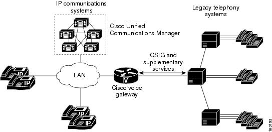
For more information about QSIG support in Cisco Unified Communications Manager, see the "Understanding IP Telephony Protocols" chapter in the Cisco Unified Communications Manager System Guide.
Configuration Examples for MGCP PRI Backhaul and T1 CAS
This section provides the following configuration example:
•![]() MGCP PRI Backhaul and T1 CAS: Example
MGCP PRI Backhaul and T1 CAS: Example
Note ![]() To view relevant configuration examples, go to the Cisco Systems Technologies website at http://cisco.com/web/psa/technologies/index.html. From the website, select Voice > IP Telephony/VoIP, then click Configure> Configuration Examples and Tech Notes.
To view relevant configuration examples, go to the Cisco Systems Technologies website at http://cisco.com/web/psa/technologies/index.html. From the website, select Voice > IP Telephony/VoIP, then click Configure> Configuration Examples and Tech Notes.
MGCP PRI Backhaul and T1 CAS: Example
In the following example, T1 CAS and PRI backhaul is configured for an MGCP gateway:
mgcp
mgcp call-agent 10.0.0.21 service-type mgcp version 0.1
mgcp dtmf-relay voip codec all mode out-of-band
mgcp modem passthrough voip mode cisco
mgcp modem passthrough voip codec g711alaw
mgcp modem passthrough voip redundancy
mgcp package-capability dtmf-package
mgcp package-capability mf-package
mgcp package-capability rtp-package
mgcp package-capability sst-package
mgcp default-package line-package
mgcp timer net-cont-test 3000
isdn switch-type primary-ni
call rsvp-sync
!
ccm-manager fallback-mgcp
ccm-manager redundant-host 10.0.0.21
ccm-manager mgcp
ccm-manager music-on-hold
! This is the PRI backhaul circuit
controller T1 3/0
framing esf
linecode b8zs
pri-group 0 timeslots 1-24 service mgcp
!
! This is the T1-CAS circuit
controller T1 3/1
framing esf
linecode b8zs
ds0-group 0 timeslots 1-24 type e&m-wink-start
!
interface Serial3/0:23
no ip address
no logging event link-status
isdn switch-type primary-ts014
isdn incoming-voice voice
isdn T306 60000
isdn bind-L3 ccm-manager
no cdp enable
!
dial-peer voice 501 pots
service mgcpapp
incoming called-number
port 3/1:0
Where to Go Next
•![]() To configure conferencing, transcoding, and MTP support on a Cisco IOS gateway, see "Configuring Enhanced Conferencing and Transcoding for Voice Gateway Routers" on page 67.
To configure conferencing, transcoding, and MTP support on a Cisco IOS gateway, see "Configuring Enhanced Conferencing and Transcoding for Voice Gateway Routers" on page 67.
•![]() To enable MGCP BRI backhaul support, see "Configuring MGCP-Controlled Backhaul of BRI Signaling in Conjunction with Cisco Unified Communications Manager" on page 129.
To enable MGCP BRI backhaul support, see "Configuring MGCP-Controlled Backhaul of BRI Signaling in Conjunction with Cisco Unified Communications Manager" on page 129.
•![]() To download region-specific tones and their associated frequencies, amplitudes, and cadences, see "Configuring Tone Download to MGCP Gateways" on page 145.
To download region-specific tones and their associated frequencies, amplitudes, and cadences, see "Configuring Tone Download to MGCP Gateways" on page 145.
Additional References
•![]() "Cisco Unified Communications Manager and Cisco IOS Interoperability Features Roadmap" on page 9—Describes how to access Cisco Feature Navigator; also lists and describes, by Cisco IOS release, Cisco Unified Communications Manager and Cisco IOS interoperability features.
"Cisco Unified Communications Manager and Cisco IOS Interoperability Features Roadmap" on page 9—Describes how to access Cisco Feature Navigator; also lists and describes, by Cisco IOS release, Cisco Unified Communications Manager and Cisco IOS interoperability features.
•![]() "Overview of Cisco Unified Communications Manager and Cisco IOS Interoperability" on page 13—Describes basics of underlying technology and lists related documents.
"Overview of Cisco Unified Communications Manager and Cisco IOS Interoperability" on page 13—Describes basics of underlying technology and lists related documents.
•![]() How to Configure MGCP with Digital PRI and Cisco Unified Communications Manager—Technical support configuration document that includes sample configurations and troubleshooting tips.
How to Configure MGCP with Digital PRI and Cisco Unified Communications Manager—Technical support configuration document that includes sample configurations and troubleshooting tips.
 Feedback